Characteristics and Weldability of Resistance Plug Welding of Dissimilar Steels
2024-01-03CENYaodongCHENLinMAXiao
CEN Yaodong, CHEN Lin, MA Xiao
(School of Materials and Metallurgy, Inner Mongolia University of Science and Technology, Baotou 014010, China)
Abstract: TRIP980 high-strength steel plate/SPCC low-carbon steel plate were welded by RPW.The key factors such as size and material of filler were studied, and the structure, fusion ratio and mechanical properties of the RPW joint were analyzed.The experimental results show that the calculation formulas of the length and diameter of the filler were designed reasonably.Q235 as a filler for RPW of TRIP980 high -strength steel plate / SPCC low-carbon steel plate is suitable according to schaeffler organization chart.The deposited metal of RPW joint is in the shape of “spool”,and the base metal and cap of deposited metal are alternately combined.The deposited metal has the characteristics of “locking” as rivets, which is beneficial to the improvement of mechanical properties of RPW joint.The nugget of RPW joint is uniform without deviates.TRIP980 high-strength steel plate, SPCC low-carbon steel plate, and filler were metallurgically bonded in the RPW joint.
Key words: dissimilar steel; resistance plug welding; nugget
1 Introduction
The automobile body structure made of advanced high-strength steel plate and low-carbon steel plate can not only get lightweight effect, but also meet the proper manufacturing cost[1].At present, there are two types connection of sheet steel: welding methods and mechanical connection method.The welding methods include resistance spot welding (RSW)[2,3], and laser welding[4],etc.However, the chemical composition, physical properties,and chemical properties of dissimilar steels are uncoordinated and inconsistent, and it is challenging to effectively weld dissimilar steels together[5,6], and the welding difficulty of dissimilar steels is much greater than that of the same steels.Mechanical connection methods include riveting[7,8], and screw[9,10],etc.The adaptability of mechanical connection to materials is better than that of welding.The characteristics of mechanical connection are no uneven deformation, hard brittle phase of interface, joint softening,etc.However, dissimilar steels have to be punched in the mechanical connection, and the strength of the joint is reduced because the bearing area of the joint is insufficient[11].Both welding methods and mechanical connection method have advantages and disadvantages, and them are not suitable for the connection of dissimilar steels.Therefore,it is necessary to study and solve the welding problem of dissimilar steel.The resistance plug welding (RPW) is a new composite welding method[12], which was first used to weld dissimilar steels (TRIP980 high-strength steel plate/ SPCC low-carbon steel plate) in our preliminary work,and the tensile shear failure load of the RPW joint was more than 20% that of the RSW joint under the same conditions[13].
In the previous research on the RPW process for us, it was found that the size of filler was a direct factor affecting the heat input of welding, and the mechanical properties of RPW joints are related to the size of fillers.Therefore, the key factors such as the length, diameter and material of the filler were studied, and the structure, fusion ratio and nugget morphology were analyzed in order to reveal the characteristics and weldability of RPW of dissimilar steel, laying a theoretical and practical foundation for the application of RPW of dissimilar steel plate for automobile.
2 Experimental
2.1 Principle of RPW
In the present study, TRIP980 high-strength steel plate and SPCC low-carbon steel plate were chosen for RPW as shown in Fig.1.The welding process of RPW is as follows: before welding, a circular throughhole should be drilled at the place where two kinds of plate metals are to be welded, then a cylindrical metal filler with well weldability should be placed into the through-hole, and then resistance spot welding be carried out.The effect of resistance heat makes the fusion between the two kinds of base metals, between the base metal and the filler occur, so as to realize the welding of the two kinds of plates.
2.2 Diameter design of filler
It can be seen from the resistance welding heat formulaQ=I2Rt, all the factors that affect the welding heat input will affect the mechanical properties of joint.Due to the existence of filler in RPW, the length and diameter of filler will inevitably affect welding resistance ofRand heat input in the welding process, and finally affect the mechanical properties of joint.If the length of filler is too long, more heat is needed to melt the filler during welding, and the rivet cap formed after the filler is compressed deformation may eventually exceed the surface of the weldment, forming reinforcement.However, if the filler is too short, the ideal rivet cap cannot be formed after welding, or although the rivet cap is formed, the rivet cap is sagged and the weld spot is indented, which will also affect the joint performance and aesthetics.So, it is necessary to calculate the length and diameter of the filler.
If the indentation depth of RSW is too deep and the nugget is close to the outer surface of the weldment,the surface metal will overheat, the grain is coarse,and the defects such as splashing, nugget shrinkage hole and crack are easy to appear, and the mechanical properties of the joint will decrease[14].If there is no indentation on weldment of RSW, the forging pressure of the nugget may be insufficient and the strength of joint may not be high enough[15].According to the process characteristics of RSW and the principle of conservation of metal mass, the main reason for the existence of indentation depth in the weldment which is a small amount of clearance on the contact surface of the two plates before welding.When the weld pool is formed,the melted metal is filled into the clearance and the metal on the outer surface of the solder joint is sunken under forging pressure as shown in Fig.2.Generally,there is a relationship between the indentation depth ofΔand the plate thickness ofδof RSW[16]:
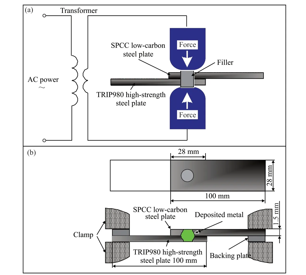
Fig.1 Schematic diagram of RPW: (a) Diagrammatic sketch;(b) Sample size and tensile tests
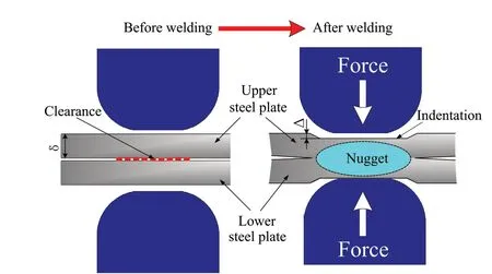
Fig.2 Clearance variation of weldment of RSW
The clearance variation of weldment of RPW is shown in Fig.3.Although there are some similarities between RPW process and RSW, the clearance position of RPW is very special due to the addition of filler and preformed through hole as shown in Fig.3(a).There are three positions with clearance before welding, the first position is between the filler and the upper steel plate,the second position is between the upper steel plate and the lower steel plate, and the third position is between the filler and the lower steel plate.All the clearance disappear after welding, the base metal near the hole and filler will plastic deformation by resistance heat and forging pressure[16].With the increase of heat input,the temperature of the filler increases.The height of the filler becomes shorter under the forging pressure, the cross section becomes wider, and the filler is flattened.The temperature of base metal and filler increases at the welding position, and then gradually melts to form a RPW joint.If the filler of different length is selected,there are three situations weldment after RPW welding.The first is that the filler is long enough so that the clearance is overfilled, resulting in post weld reinforcement as shown in Fig.3(b), weld reinforcement will affect the surface finish of the RPW joint.Moreover,too long filler will not only consume resistance heat,but also cause incomplete welding of RPW joints,which will affect the mechanical properties of joints.The second is that the length of filler is insufficient, so that the clearance is underfill after welding, resulting in post weld indentation as shown in Fig.3(c), affecting the surface finish of RPW joint.Moreover, too short filler cannot form rivet cap, but also lead to overheating of RPW joint welding, which affects the mechanical properties of the joint.The third is that the clearance is just filled, and the filler with appropriate length forms the perfect deposited metal and nugget as shown in Fig.3(d), forming the appropriate rivet cap, and there is no indentation and weld reinforcement after welding,which is the most perfect result.
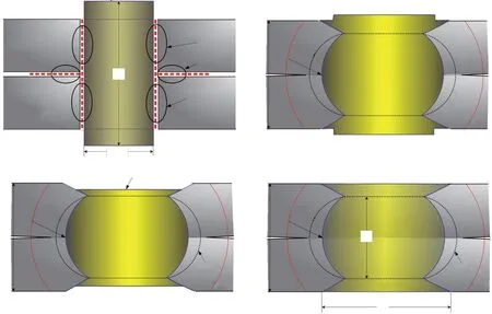
Fig.3 Clearance variation of weldment of RPW: (a) Clearance before welding;(b) Reinforcement after welding; (c) Indentation after welding;(d) No indentation and reinforcement after welding
The theory of welding and nugget formation of RPW is reasonably explained as follows: the nugget volume must be larger than the weld metal volume to ensure the metallurgical bonding of RPW joints, so the intersection of the three materials must be inside the nugget as shown in Figs.3(c)-3(d).The nugget is surrounded by the black dotted line, and the edge of the deposited metal formed by the blue dotted line must be inside the nugget, and the heat affected zone (HAR) is the part between the orange dotted line and the black dotted line.Therefore, the aim of selecting filler length of RPW is under the premise of ensuring metallurgical combination between base metal and filler, there is no indentation and reinforcement after welding, and the surface finish is perfect[17].
According to the above analysis of Fig.3, to ensure that the surface of weldment is level with the surface of base metal, there is the following relationship between the volume of the extended part of the filler ofV1and the volume of the indentation ofV2:
Since the indentation diameter is approximately equal to the diameterdeof the end face of the electrode tip diameter, the relation is obtained from formula (2):(h-2δ)/2×(dk/2)2π=(de/2)2Δπ, and the formulae (1) and(2) can be used to calculate the filler length when there is no indentation and reinforcement:
Sonali picked up some dirt in her hands, folded her hands in prayer and began singing a beautiful hymn14 she learned in India the previous winter. Everyone stopped to listen to her. Then she held the dirt to her heart and threw it toward the plane.
where,his the filler length, mm;dethe end diameter of electrode head, mm;dkthe filler diameter, mm.
According to the standard of American Welding Society (AWS) on RSW quality inspection[18], the nugget diameterD≥4δcan meet the performance requirements of the joint.Considering that the nugget diameter must be larger than the filler diameter to ensure the metallurgical bonding of RPW joint, the filler diameter range shall be:
According to the formula (4) and the sample size in Fig.1, the appropriate filler diameter range and filler lengths are calculated.The closest filler theoretical diameterdk= 5 mm can be calculated.Because the diameter of electrode head selected in this experiment is 8 mm,his 3.41-3.60 mm according to formula (3).
2.3 Material design of filler
The carbon equivalent has a great influence on the weldability, and the carbon equivalent of TRIP980 high-strength steel plate and SPCC low-carbon steel plate is different.Theoretically, if the deposited metal with carbon equivalent between the two base metals is selected, the structure and composition of the fusion zone will be better transited, which is beneficial to the improvement of weldability of dissimilar steels.To study the relationship between the composition and the performance of the RPW joint and find the most suitable filler, three commonly used steels are selected,and the carbon equivalent is ranked from low to high,which are Q235, Q345, and 45# steel, respectively.The schaeffler organization chart has good applicability in selecting electrode or filler in the welding process of dissimilar steel[20-22], the quantitative relationship between chemical composition and phase structure of deposited metal in RPW of TRIP980 high-strength steel plate and SPCC low-carbon steel plate is characterized by the schaeffler organization chart.According to the calculation formula of [Cr] equivalent and [Ni] equivalent recommended by American Welding Society:
Table 1 shows the carbon, chromium and nickel equivalent of TRIP980 high-strength steel, SPCC low-carbon steel and various fillers calculated according to formula (5).
Fig.4 shows the schaeffler organization for TRIP980 high-strength steel plate, SPCC low-carbon steel plate.According to the [Ni] and [Cr] in Table 1, TRIP980 high-strength steel plate ofaand SPCClow-carbon steel plate ofbare found in Fig.4.If there is no deposited metal filled, thea-bconnection can be regarded as RSW of dissimilar steels.The midpointfof thea-bconnection of dissimilar steels are mixed in the same proportion is the average composition of the base metal to be welded.
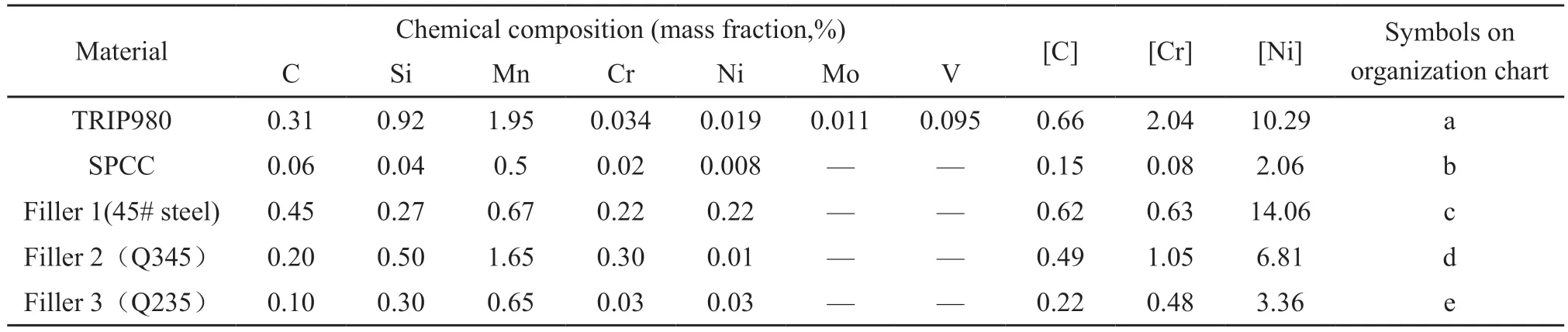
Table 1 Carbon, chromium, and nickel equivalent of materials
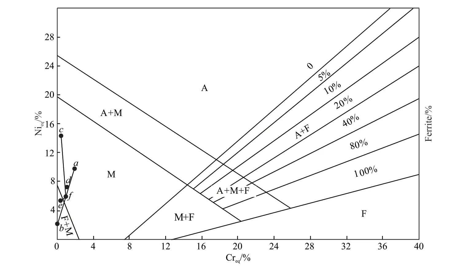
Fig.4 Schaeffler organization chart
Table 2 Factors and levels of orthogonal test
In the same way, the composition of filler 1,filler 2, and filler 3 can be determined asc,d, and e respectively.Assuming that the base metal withf-point composition is fused with the filler, the weld metal is formed.The specific composition should be located on the line off-c,f-d, andf-e, and depends on the large and small fusion ratio.The connecting lines off-candf-dlines will be in M (martensite) region at any fusion ratio.Therefore, if filler 1 (45 # steel) and filler 2(Q345) are selected for RPW, the weldment is full of brittle hard martensite structure, which is not in accordance with the welding requirements.If thef-ewire is connected, the fusion ratio is 10%-30%, and the line segment is in the structure area of F (ferrite) + M, and the F + M dual phase structure can be obtained.The plasticity of weldment will be well because of the existence of soft matrix of ferrite.Moreover, martensite is the second phase with high hardness in the dual phase structure, which can resist crack growth and improve the joint performance.Therefore, filler 3 (Q235) is the most suitable choice.
2.4 Design of key process parameters
Q235 as filler was used study of TRIP980 highstrength steel plate and SPCC low-carbon steel plate of RPW.The grit sandpaper 600 to 1000 were selected to ground the sheet surfaces, and then the specimens were cleaned in acetone and dried before welding.The RPW was performed with a DN-50B spot welding machine with an electrode tip diameter of 8 mm.To evaluate the mechanical strength of the joints, tensile tests were performed utilizing a tensile machin of NCS Testing Technology Co., Ltd, and the constant displacement rate of 1 mm / min at room temperature.In the lap shear tensile testing process, backing plates were employed to minimize the rotation of the joints and keep the tensile load in a plane as long as possible.To study the influencing factors of the mechanical properties of the RPW joint, the key parameters were considered for welding current of 9-12 kA, welding time of 20-35 cycle, electrode pressure of 2.5-4.0 kN, and filler diameter of 4.5-6.0 mm, filler length of 3.45-3.60 mm.Therefore, the orthogonal testL16(45) of 16 groups of experiments were designed as shown in Table 2.The tensile shear load of RPW joint was taken as an evaluation index,and three specimens were tested under the same welding parameters.
3 Results and discussion
3.1 Tensile properties of joints
The results of tensile shear load of orthogonal test are shown which the samples of key process parameters with welding current of 10 kA, welding time of 35 cycle, electrode pressure 3.5 kN, filler diameter of 5.0 mm, and filler length of 3.45 mm which has the highest tensile shear load 10.458 kN, so the sample was selected as the best sample for further study, and it was cut from the cross section of the RPW joint.The microstructure was characterized using an laser scanning confocal microscope and Tescan GAIA3 SEM-FIB.The MTP-1A-type Electro Polisher, and 5% perchloric acid and 95% methanol (volume fraction) electrolyte were to thin the transmission electron microscopy(TEM) sample of the RPW joint.The experimental temperature was -25 ℃, and the voltage was 15 V.
Fig.5 shows the weldment and tensile performance curve of the best sample of RPW joint.There is an obvious welding plastic ring on the RPW joint, the RPW joint is no indentation and weld reinforcement as show in Fig.5(a).The displacement of the RPW joint is 14mm as show in Fig.5(b) and Fig.5(c), the displacement of the RSW joint is 3.7 mm[26], so the elongation of RPW joint is more than the RSW joint, and there is no obvious brittle fracture stage in the tensile displacement curve.Therefore, we can judge that the RPW joint has high elongation and excellent fracture toughness.
3.2 Component dilution of RPW joint
The fusion ratio is mainly used to determine the proportion of base metal in the weld metal, which has an important influence on the composition, morphology and properties of the joint[23,24].Especially for the RPW of dissimilar steels, the melting of filler has more influence on the composition, structure and properties of weld because of the difference between the two base metals and filler.The welding metal consists of deposited metal and melted base metal.When the dissimilar steel joint are melted, the calculation formula of the mass fraction of an element in the joint[25]:
where,wwis the mass fraction of an element in weld metal, %;wdthe mass fraction of an element in deposited metal, %;wb1the mass fraction of an element in base metal 1, %;wb2the Mass fraction of an element in base metal 2, %;kthe relative fusion ratio of two base metals,k=J1/J2×100% (J1,J2is the area of the two base metals in the weld section);θthe fusion ratio, %.
The fusion ratio ofθrefers to the proportion of the base metal partially melted in the weld metal:
where,mbis the mass of the melted base metal in the weld;mdthe mass of deposited metal in weld.
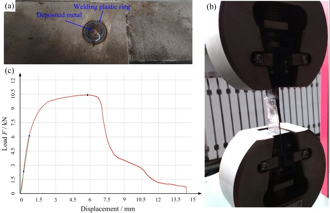
Fig.5 Mechanical properties of RPW joint
The best sample with the highest tensile shear load was selected, which the joint cross section is shown in Fig.6.The filling material changes from cylinder (surrounded by black solid line) before welding to deposited metal (surrounded by black dotted line)after welding, which is conducive to the improvement of mechanical properties of the joint.The nugget is surrounded by blue dotted line.
According to formulas (1) and (2), when the fusion ratio of weld is calculated, it is necessary to determine the mass of base metal and the mass of deposited metal in weld.These two sets of data are obviously not easy to obtain.When the density difference between base metal and deposited metal is ignored, the mass of the base metal melted by the weld in the above formula is replaced by the volume.The metallographic corrosion of the cross section of the joint were observed and measured, and the data were obtained:dk= 5.5 mm,L1= 5.66 mm,de= 5.92 mm,L2= 6.54 mm,H= 3.5 mm,H1= 3 mm, andH2= 2.88 mm.According to the analysis of nugget shape in Fig.5, theV3(V3is the volume of filler, mm3) is as follows:
Assuming that the nugget is a regular round table type, theV4(V4is the volume of weld metal, mm3) is shown as follows:
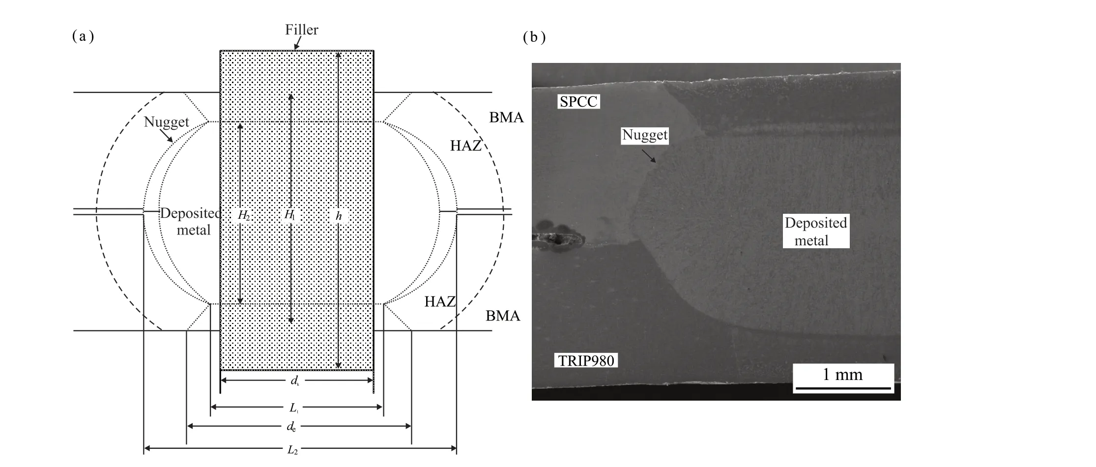
Fig.6 Cross section of RPW joint: (a) Schematic diagram; (b) Low multiple organization chart
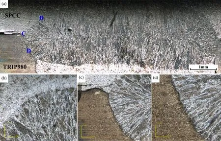
Fig.7 Cross section organization of RPW joint:(a) Macrostructure;(b) B location organization of a; (b) C location organization of a; (b) D location organization of a
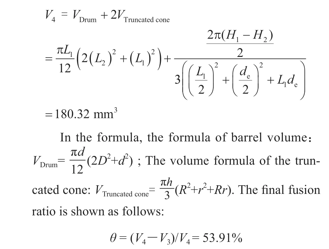
Based on the above calculation, it is determined that theθof filler in weld metal is 53.91%.It can be seen that the volume of weld metal is much larger than the volume of original filler.According to the principle of mass conservation, the weld metal is composed of the metal from filler and the metal from two base metals.After welding, the filler as the deposited metal, eventually becomes a part of the joint, and fusion occurs between the filler and the base metal.It can be seen from the Fig.6(b) that the weld metal consists of a drum nugget and two truncated cone, and the interface of the three materials must also be inside the nugget boundary line, specifically at the intersection of the black dotted line in Fig.6 (a).
3.3 Microstructure observation and TEM analysis of nugget
Fig.7 shows the microstructure of the best sample.The formed joint is composed of drum nugget area and truncated cone as shown in Fig.7(a), which proves that metallurgical bonding is realized between the base metal and filler at the edge.Fig.7(c) shows the microstructure of the intersection of the three respectively,the nugget has expanded in this interface region, which is due to the slow heat dissipation in the zone during the resistance heating process.The microstructure of fusion zone on TRIP980 high-strength steel plate side and SPCC low-carbon steel plate side is different as shown in Fig.7(b) and Fig.7(d).The microstructure on SPCC low-carbon steel side is affected by the concentration effect of welding thermal cycle current, forming austenite coarse crystal area and fine crystal area due to the similar carbon equivalent.The microstructure of TRIP980 high-strength steel plate side is also affected by welding thermal cycle and different expansion, but the composition of filler and base metal is different,and this region is mainly martensitic, and the structure near the filler is larger than that near the base metal.
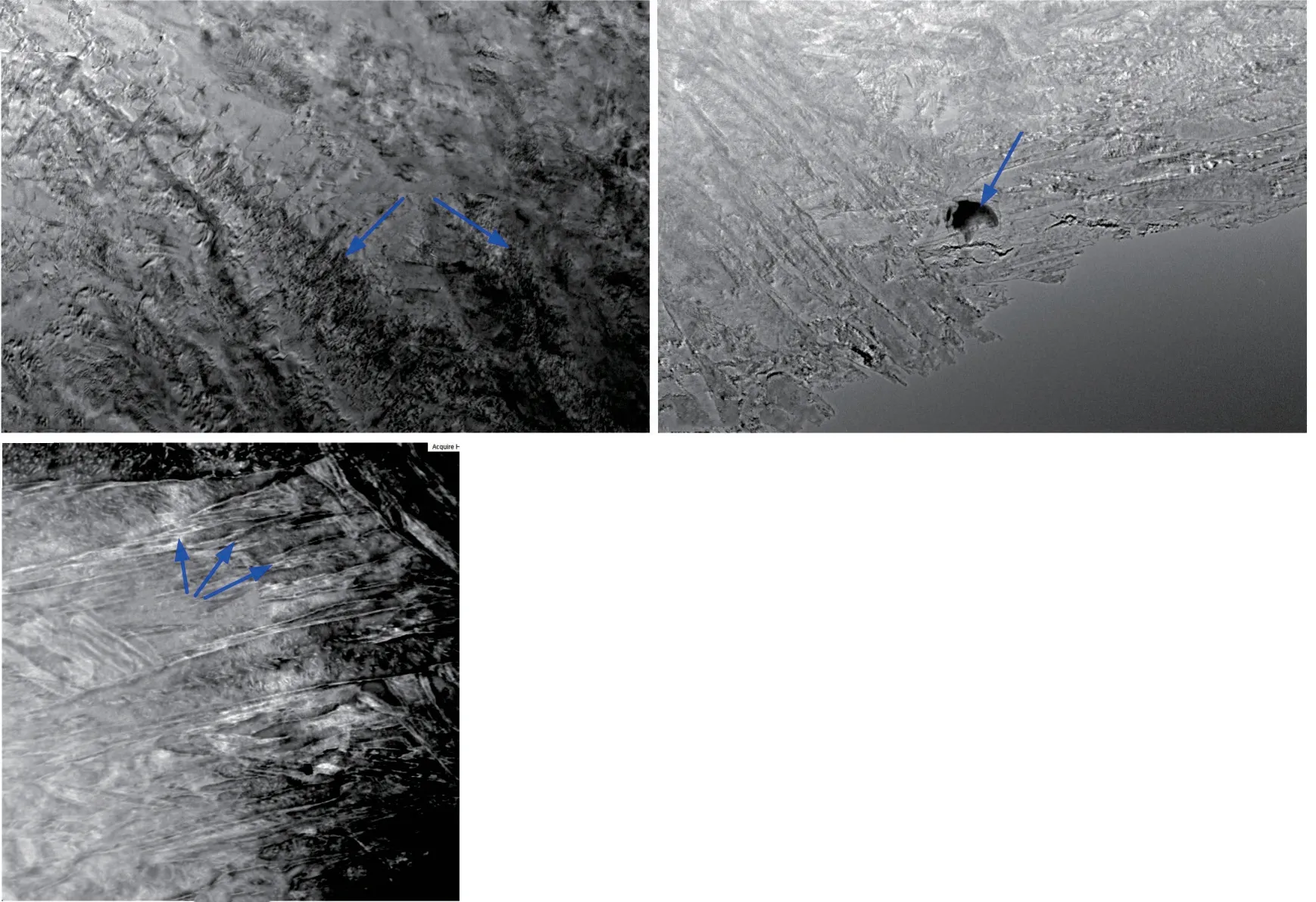
Fig.8 TEM images of fusion zone of the intersection of the three materials in the RPW joint
To study the microstructure, micro phase and crystal defect of RPW joint, the fusion zone of the intersection of the three materials was observed and analyzed by transmission electron microscopy (TEM).Fig.8 shows the measurement results of the microstructure of the best sample of RPW joint, and Fig.8(a)shows the dislocation observed in the fusion zone, with a width of 100-300 nm.Fig.8(b) shows the pores in the fusion zone with the size of 800 nm.The reason is that in the process of nugget formation and expansion, the brittle phase of intermetallic compound is formed in the fusion zone due to the diffusion and combination of atoms.Fig.8(c) shows the structure of the fusion zone at the interface, which is mainly lath martensite with different orientations, which is consistent with the previous metallographic observation results.The alloy composition of pores was studied by EDS attached to TEM.According to the scanning analysis, the elements and contents of pores in Fig.8(d) of C-4.66%, Al-22.64%,Si-0.57%, and Mn-0.51%.EDS results showed that the pores were mainly C, Al, Si, Mn, and other compounds.
4 Conclusions
a) According to the size analysis of indentation depth and nugget size of RPW joint, the empirical formula of filler length is obtained:h=and the empirical formula of filler diameter is obtained:dk≤4δ.The key welding parameters with welding current of 10 kA, welding time of 35 cycles, electrode pressure 3.5 kN, filler diameter of 5.0 mm, and filler length of 3.45 mm which has the highest tensile shear load are designed by orthogonal test in this experiment.
b) According to the calculation of the fusion ratio of the RPW joint and the observation of the metallographic structure of the joint, the nugget structure is mainly martensite, and the filler is determined as a part of the final joint of the deposited metal, the deposited metal is in the shape of “spool”, and the rivet cap and the base metal are combined alternately, the “locking”property of the deposited metal is beneficial to the improvement of the mechanical properties of the RPW joint.
c) Three types of fillers which the carbon equivalent between two base metals are selected and compared by schaeffler organization chart, and the Q235 as filler is suitable for RPW of TRIP980 high-strength steel plate/SPCC low-carbon steel plate.The RPW joint is no indentation and weld reinforcement.The RPW joint has high elongation and excellent toughness.
Conflict of interest
All authors declare that there are no competing interests.
杂志排行

Journal of Wuhan University of Technology(Materials Science Edition)的其它文章
- Enhanced Electrochemical Performances of Ni Doped Cr8O21 Cathode Materials for Lithium-ion Batteries
- Design on the Prestressed Concrete Frame Beam-column
- Synthesis and Flocculation of Polyacrylamide with Low Water Absorption for Non-dispersible Underwater Concrete
- Experimental Behavior of Recycled Aggregate Concrete Filled Steel Tubular Columns
- Impact-abrasive Wear Behavior of ZTA and NbC Reinforced Fe60 Matrix Composites
- Synthesis and Characterization of Hollow Strontium Carbonate Pompons by Composite Soft Template Method