Design on the Prestressed Concrete Frame Beam-column
2024-01-03ZHANGTaiyueZHANGWeiguoWANGSihaiGUOYiqing
ZHANG Taiyue, ZHANG Weiguo, WANG Sihai, GUO Yiqing
(1. Architectural Engineering Institute, Jiangsu College of Engineering and Technology, Nantong 226000, China; 2. Nantong Sijian Group Co., Ltd, Nantong 226000, China; 3. School of Materials Science and Engineering, Tongji University, Shanghai 201804, China)
Abstract: A bidirectional ribbed concrete beam slab structure was widly adopted for the upper space of industrial buildings.To maintain ample space and minimize the presence of conventional columns, a bidirectional prestressed concrete beam is often employed.The intersection node of the prestressed concrete frame beam column was characterized by a high density of steel reinforcement, significant structural loads,and complex construction requirements.To ensure the quality, safety, and progress of prestressed frame beamcolumn intersection nodes during construction, this article proposed a new technology for constructing such nodes, which includes setting the tensioning and haunching ends of nodes at different positions, using ABAQUS finite element software to optimize the design of cross-sectional dimensions, conducting stress analysis simulations.
Key words: prestressed concrete; beam-column intersection node; finite element analysis; optimal design; digital simulation
1 Introduction
In recent years, China’s construction technology has continuously improved resulting in the creation of numerous landmark public buildings that are both aesthetically pleasing and practical due to their tall and spacious designs.Large-span continuous frame beam structures are commonly utilized in industrial and civil buildings.However, the construction of prestressed frame beam structures at beam-column nodes presents numerous challenges, primarily including the prestressed corrugated pipes and steel bars are interlaced, forming a complex steel bar structure with an indiscernible flat plan; It is challenging to achieve the desired level of prestressing force due to the extended length.The insufficient axial preload stress will make it difficult to meet the requirements for crack resistance performance under temperature changes and concrete shrinkage[1,2]; The concentrated load of the prestressing anchor node often results in concrete beam cracking and potential safety hazards arising from tensioning and anchoring.
Although various countries have regulations governing the design of beam column joints, there are discrepancies in the joints design methods prescribed by these regulations, resulting in variations in calculated outcomes based on national standards[3-5].Currently,the design and construction of frame continuous beams overlapping structures in China primarily rely on the standard atlas 06SG429[6], which exhibits three distinct types of overlapping.The first type involves reserving tension grooves on the surface of the beams that will be overlapped.As shown in Fig.1, beams with wider upper surfaces can be placed side by side, and beams with narrower upper surfaces can be staggered by a certain distance.The second approach involves incorporating haunches on the beam’s sides, with prestressed steel bars being tensioned externally to the beam.The third method is to overlap at the post pouring strip, as shown in Fig.2.When prestressed splicing is installed on three or four sides, the annotation method in the atlas is challenging to comprehend, and its reference value is limited.The steel bars located the beam-column nodes of the frame exhibit a high degree of complexity and cannot be adequately represented in two-dimensional space.To date, there is relatively little research on the three-dimensional digital design of such prestressed frame beam column nodes.
In order to enhance construction safety, it is necessary to study the intersection nodes of such structures to improve construction quality.In this study, two types of node structures were innovatively designed to achieve the construction method of continuous overlap, continuous anchoring, and continuous tensioning of prestressed frame beams.Furthermore, an innovative approach to the design of prestressed frame beam intersection nodes was proposed.Finite element simulation was conducted to make the stress analysis and optimize the design.
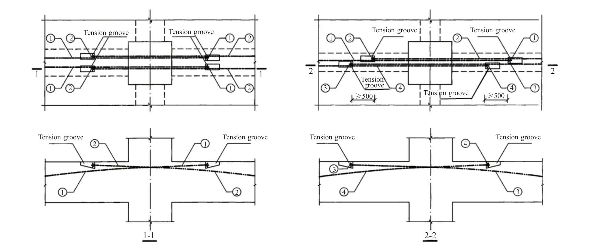
Fig.1 Beam surface groove tensioning and overlapping diagram
2 Innovative design of the nodes on the prestressed frame beams
This article is based on the research of a logistics park project.The project is 136.4 meters long and 126.9 meters wide, and adopts a bidirectional ribbed beam plate structure to minimize the presence of typical columns while increasing column spacing.In order to achieve a spacious interior, prestressed frame beams have been utilized.The structure is subject to heavy loads and features large column spacing, with the rib beams filled with prestressed reinforcement that bear most of the load capacity.As such, it demands high standards for the construction quality of prestress.If the prestressed reinforcement is not overlapped in sections, the construction length is too long, and the crack resistance of the concrete beam cannot meet the requirements.
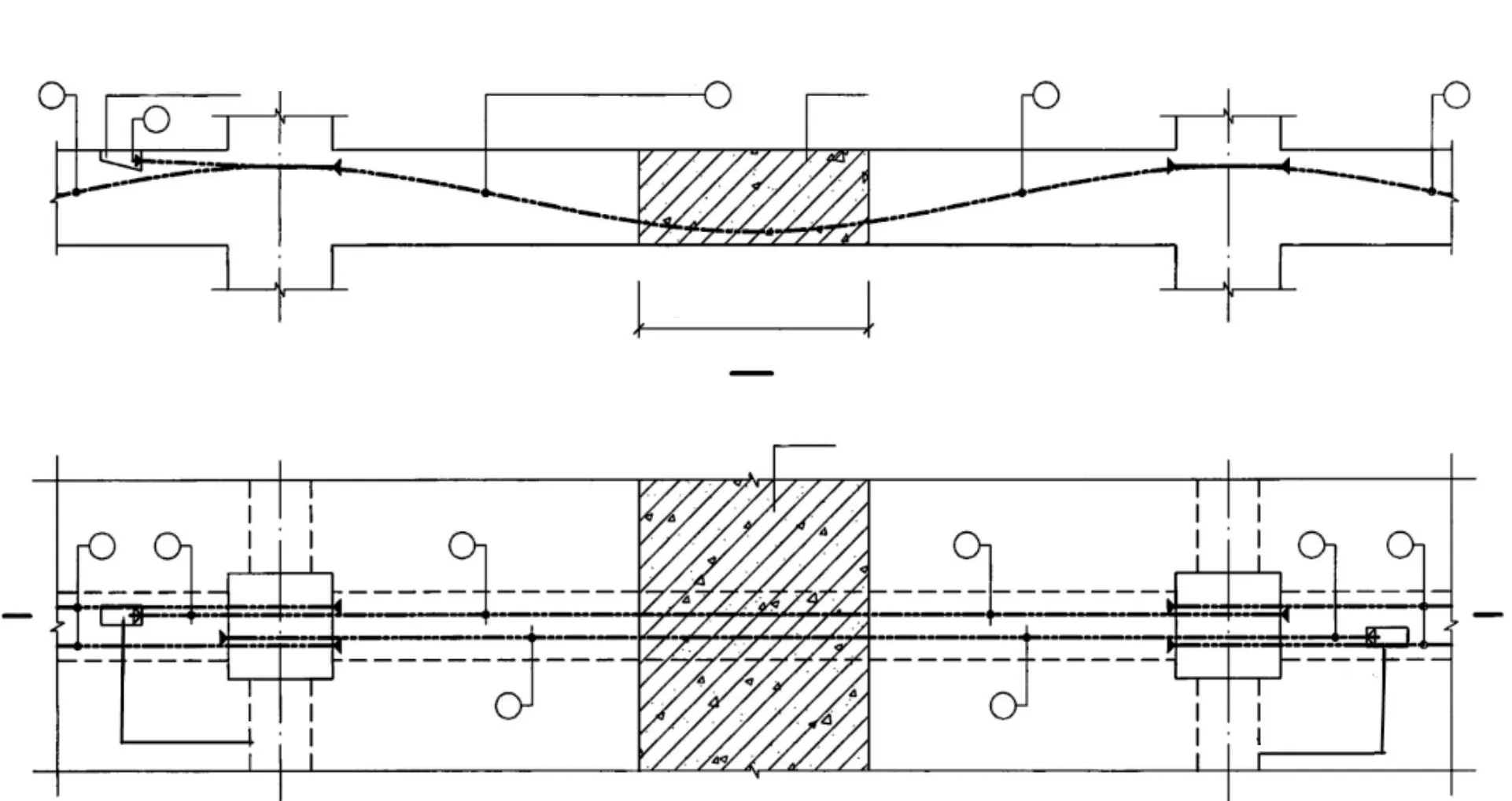
Fig.2 Overlap diagram of prestressed reinforcement using post cast strip
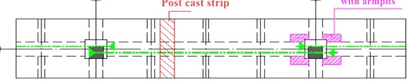
Fig.3 Schematic of node tensioning end haunching design and post pouring strip
Considering the prestressed frame continuous beam concrete structure exceeding 100 meters is a rare occurrence in current warehousing practices[7,8], this project has innovated the construction at the node of the cross continuous beam by adding the haunches,as shown in Fig.3, which can realize the section construction, section tension, and combine the postcast strip as the boundary to divide the construction.This approach not only minimizes the prestress loss and effectively utilizes the prestressing force on the floor, but also facilitates seamless integration with other construction activities, to achieve flowing construction,resulting in reduced labor requirements and shorter project timelines while achieving optimal engineering outcomes.
According to the design characteristics of the project, two kinds of cross node structures of frame beams are innovatively designed.A prefabricated T-beam wing plate post tensioned prestressed frame beam column node structure is shown in Fig.4.The PC structural column and PC composite T-beam form a prefabricated frame structure.The upper ends of the PC composite T-beam are equipped with PC composite T-beam wing plates, which are integrated and formed in the PC factory.The PC composite T-beam wing plates are internally equipped with unbonded prestressed steel bars, and the upper part of the PC composite T-beam is equipped with extended steel bars.The upper extension steel bars of the composite T-beam are effectively connected to the composite plate truss bars of the composite plate.At the same time, the composite plate truss bars of the adjacent two composite plates are“mutually anchored” at the middle composite T-beam.After all installation is completed, the construction of the overall post-cast concrete surface layer is carried out on the upper part.
One type of construction method is the onsite cast-in-place frame beam cross node.To achieve continuous overlap, anchoring, and stretching of prestressed steel bars in the frame beam, innovative designs have been implemented for the middle beam node, edge beam node, and column outer protruding tension node based on their respective positions as depicted in Fig.5.
3 Finite element modeling of the nodes on prestressed frame beam column
3.1 Material property
The project is a logistics and storage project, and its structural layout is a two-way ribbed beam slab structure.The prestress is arranged in the frame beam and secondary beam.The frame beam is provided with bonded prestressed tendons, and the secondary beam is provided with unbonded prestressing tendon.The parameters and mechanical properties of prestressed tendons are shown in Table 1.Parameters of C50 concrete are shown in Table 2.
3.2 Modeling
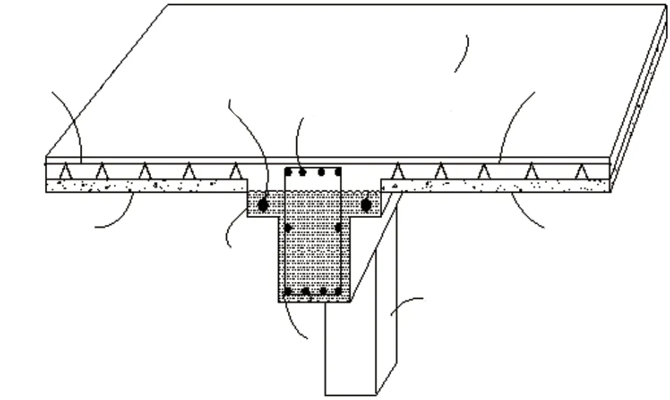
Fig.4 Cross section construction node of T-beam under PC board
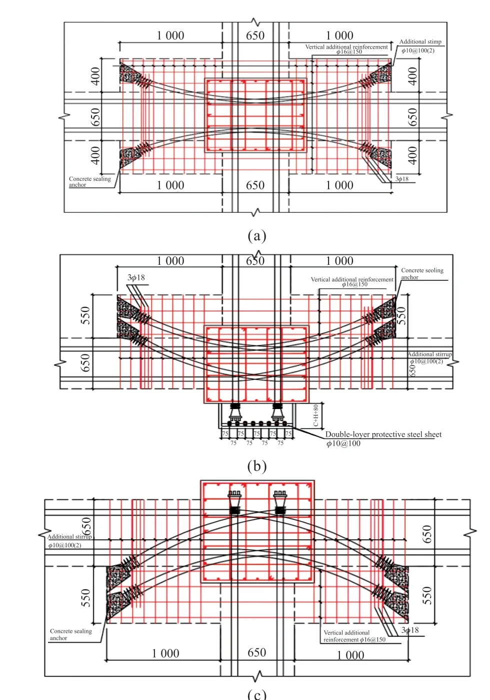
Fig.5 Schematic of beam column intersection nodes at three positions: (a) Frame beam middle beam node; (b) External protruding tension node of column; (c) Frame beam edge beam node
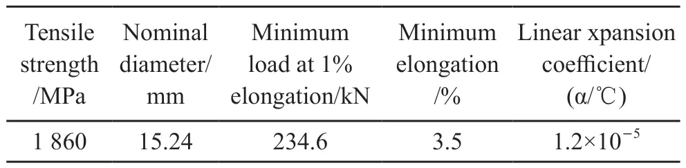
Table 1 Mechanical properties of prestressed tendons
ABAQUS software was used for this finite element simulation.For the research on energy dissipation performance of asymmetric hybrid connection beam joints, CDP constitutive model should be used for joint finite element model to simulate concrete performance[9-12].The stress-strain relationship model recommended in design code for concrete structure (GB 50010-2010)[13]is adopted for the concrete beam.Considering the main compression of the prestressed beam, the expression is as follows:
where,x=ε/εc0,y=σ/σc0,εandσrepresent concrete compression strain and stress, respectively.The expressions of the parametersαa,αbare shown in GB 50010-2020.
Prestressed tendon modeling use cooling method.Specify an initial temperature for the tendon element and a cooling rate to induce shrinkage deformation in the said element.This initial strain will make the tendon produce a pretension effect, which is the prestress of the model[14,15].The cooling formula of reinforcement is:
where, ΔTis the temperature drop value of the tendon;Pthe applied value of prestress;Ethe elastic modulus of the tendon;Athe sectional area of the reinforcing bar.
C3D8R element (that is, eight-node linear hexahedral element) is adopted for grid division concrete.Enhancement was selected in the hourglass control.The T3D2 truss element is utilized as reinforcement skeleton, while the T3D2 truss element is serves as prestressed reinforcement in creating a finite element model of four kinds of nodes in a prestressed frame beam column.The stress analysis of the nodes in the prestressed frame beam column during construction simulation indicates a safe state as illustrated in Fig.6.Therefore, the size and construction sequence of the four nodes can be further optimized.
4 Section optimization design of the nodes on prestressed frame beam column
There are two section designs for this project.One is the T-beam section structure node under plate.The wing thickness is 180 mm, the beam height is 1000 mm, and the beam rib width is 300 mm, as shown in Fig.4.The other is the rectangular beam section structure.The frame beam section size is 650 mm×1 000 mm, as shown in Fig.5.The finite element software is used for force analysis, and optimal section design by comparison.
4.1 Optimization design of T-beam section structure node under plate
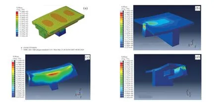
Fig.6 Mechanical simulation of (a) T-beam section construction node under PC board; (b) Beam node in frame beams; (c) Frame beam edge beam node; (d) Protruding tension joints on the outer side of columns
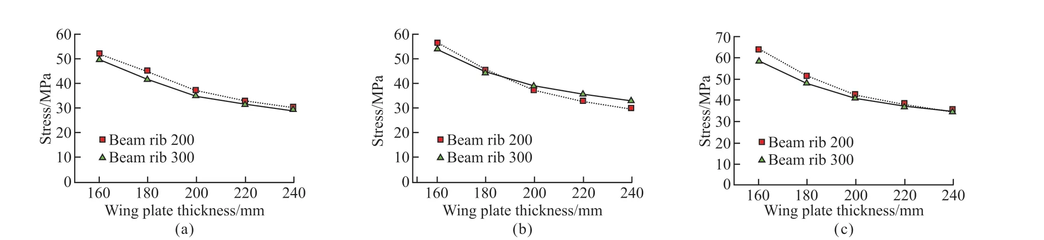
Fig.7 Optimization design of T-beam section structure node under plate: (a) h = 800 mm; (b) h = 900 mm; (c) h = 1000 mm
Firstly, stress analysis of section design of T-beam.The new technology of T-beam was mainly used as a section beam to replace the secondary beam.For the purpose of facilitating construction, the height of beams is commonly designed to fall within the range of 800 to 1 000 mm.Therefore, the beam height is selected as 800, 900, and 1 000 mm.The beam rib width was set at either 200 or 300 mm.Wing plate thickness ranged from 160 to 240 mm in increments of 20 mm.In stress analysis using the factor replacement method, when the flange plate thickness ranges from 160 to 240 mm, the force is analyzed by adjusting the beam rib width and flange plate thickness accordingly.The force analysis of T-beam section is shown in Fig.7.
It can be seen from Fig.7 that the width of the T-beam rib has little effect on the stress, while the thickness of the flange plate has a great effect on the stress.However, when the height thickness ratio reaches a certain value, the change slows down.Therefore, when designing the section size of the T-beam, the ratio of the beam height to the thickness of the flange plate is the main concern.The width of the beam rib can be de-signed according to the design specifications.Therefore, according to the above chart, it is most economical and appropriate to select the beam height of 900 mm, flange plate thickness of 200 mm, and beam rib width of 300 mm.By selecting this section size, the thickness of the flange plate is increased while reducing the beam height, resulting in a material savings of approximately 9.1%.
4.2 Optimum design of frame beam section size

Fig.8 Comparison of stress of frame beams with variable crosssection
The frame beam section is designed as 650 mm×1 000 mm and the length is about 16 m.The beam section height is designed according to 1/18-1/10 of the beam span.The section height is between 888 mm to 1 600 mm.The beam height is 900, 1 000, and 1 100 mm.The design is carried out according to the structural design specifications.The beam width can be 550 to 750 mm, increasing every 50 mm, and the factor replacement method is still used for analysis.The control prestress is 1 395 MPa.The stress analysis of frame beam section is shown in Fig.8.
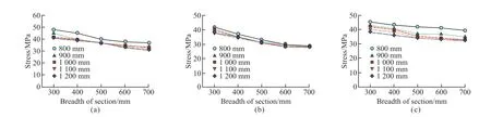
Fig.9 Optimization analysis of section size of node haunch plate; (a) The section height is 400 mm; (b) The section height is 500 mm; (c)The section height is 600 mm
It can be seen from Fig.8 that when the height of the beam is unchanged, the width of the beam increases, and the maximum principal stress of the concrete decreases.However, with the increase of the width, the stress decreases slowly.When the width is fixed, the greater the height is, the slower the stress effect will be.Therefore, when selecting the prestressed concrete rectangular section, it is more eco-nomical and reasonable to choose the size in the middle.Therefore,the frame beam section of this project is 700 × 900 mm is most reasonable.The frame beam reduces the beam height on the basis of increasing two widths, which can ensure safe construction and save about 3.12% of materials at the same time.
4.3 Optimization analysis of cross beam column node haunched plate section
In order to achieve continuous and fast tensioning during the tensioning construction process of largespan prestressed frame beams, this article designs a structure with haunched plates on the beam side of the intersection node of the frame beam and column as the tensioning and anchoring of the prestressed reinforcement.The haunched plates are the main structure that bears the pressure of the prestressed reinforcement, and their cross-sectional dimensions are particularly important.Too small a section can easily cause concrete crushing, while too large a section can result in significant structural damage and waste of materials.Therefore, it is necessary to choose the optimal section.
The optimization design of the haunched plate section is divided into three nodes: the middle beam node, the edge beam node, and the protruding tension node on the outside of the column.Initially, according to the relevant specifications for concrete structures,the dimensions have been preliminarily designed.The section size of the haunched plate at the middle beam node of the frame beam is 1 000 mm×400 mm×500 mm, as shown in Fig.5(a); The cross-sectional size of the haunch plate at the edge beam node of the frame beam is 1 000 mm×550 mm×500 mm, as shown in Fig.5(b); The cross-sectional size of the protruding tension node and haunch plate on the outer side of the column is 1 000 mm×550 mm×500 mm, as shown in Fig.5(c).
Firstly, the cross-sectional dimensions of the beam nodes in the frame beam are optimized using the factor replacement method.Due to the need to leave sufficient space for anchor sealing, the width and height of the section need to be greater than 300 mm, and the section width is set to 300, 400, 500, 600, and 700 mm.According to the concrete structure specifications,the section height is set to 400, 500, and 600 mm, and the section length is set to five dimensions: 800, 900,1 000, 1 100, and 1 200 mm, Conduct finite element stress analysis simulation.The simulation results are shown in Fig.9.
As shown in Fig.9, it can be seen that when the cross-sectional height changes between 400,500, and 600 mm, the haunched plate bears a greater force at a height of 400 mm, which is above the limit force.However, at a height of 600 mm, the force is not economical enough, so the height is chosen as 500mm.It can be seen from Fig.9 that when the height and width are fixed, the force on the haunched plate changes little with the change of the length of the haunched plate, and the data are relatively close.The shortest length can be selected in the length.When the length and height are fixed, the force on the haunched plate decreases rapidly in the early stage and tends to be flat in the later stage with the increase of the width of the haunched plate.Therefore, the width of the haunched plate can be selected as 500 mm, which is the most economic security.The cross-sectional size of the beam node in the frame beam can be designed as 800 mm×500 mm×500 mm.
5 Conclusions
This article introduces innovative designs for prestressed frame beam-column joints.Through the utilization of ABAQUS finite element software, stress simulation analysis was conducted on four types of joints within the new technology.Optimization design was performed by considering cross-sectional dimensions.The section dimensions of T-beam under slab and frame beam have been optimized, resulting in reduced concrete consumption while ensuring construction quality and safety.Specifically, the section size of T-beam under slab is optimized as beam height 900 mm, wing plate thickness 200 mm, beam rib width 300 mm, and frame beam section size 700 mm× 900 mm, saving about 9.1% and 3.12% of materials,respectively.
Conflict of interest
All authors declare that there are no competing interests.
杂志排行

Journal of Wuhan University of Technology(Materials Science Edition)的其它文章
- Enhanced Electrochemical Performances of Ni Doped Cr8O21 Cathode Materials for Lithium-ion Batteries
- Synthesis and Flocculation of Polyacrylamide with Low Water Absorption for Non-dispersible Underwater Concrete
- Experimental Behavior of Recycled Aggregate Concrete Filled Steel Tubular Columns
- Impact-abrasive Wear Behavior of ZTA and NbC Reinforced Fe60 Matrix Composites
- Synthesis and Characterization of Hollow Strontium Carbonate Pompons by Composite Soft Template Method
- Preparation of Co/CoOx Derived from a Lowtemperature Etching of ZIF-67 for Oxygen Reduction and Oxygen Evolution Catalytic Reaction