Effect of Rare Earth Doping on the Tensile Properties of High Temperature Oxidation Coating
2024-01-03ZHANGShileiLIShuaiZHAOYuncaiWANGXimaoLIUCunyu
ZHANG Shilei, LI Shuai, ZHAO Yuncai, WANG Ximao, LIU Cunyu
(School of Mechanical and Electrical Engineering, Jiangxi University of Science and Technology, Ganzhou 341000, China)
Abstract: The failure process was characterized by complex diffusion of elements in the bonding layer, TGO growth and growth stress inside the coating.We studied the aluminum migration phenomenon of NiCoCrAlY and NiCoCrAlYHf coatings under high temperature oxidation, TGO growth characteristics, the microstructure and composition of the bonding layer, and integrates them into the description of the surface strain under coating tension.The experimental results show that the TGO growth rate of NiCoCrAIYHf coating is lower than that of NiCoCrAIY coating, and the formed TGO is thinner.After high temperature oxidation,the cracking time of NiCoCrAIY coating is advanced, while the cracking time of rare earth doped coating is delayed.The addition of rare earth elements can effectively inhibit the generation of spinel phase, improve the fracture toughness of TGO, refine the grains in the bonding layer, and increase the grain boundary strengthening by 29.1 MPa which is consistent with the experimental value.Therefore, the yield strength of the doped coating is improved and the crack time of the coating is delayed.
Key words: thermal barrier coating; NiCoCrAlYHf; thermal growth oxides; high temperature oxidation;surface crack
1 Introduction
The bonding layer in the thermal barrier coatings (TBCs) system has the function of resisting high temperature oxidation and protecting the alloy matrix[1-3].In the actual service process, aviation turbine blades will experience tens of millions of rotations,and the turbine blades will be subjected to continuous tensile loads.At this time, the thermal barrier coating is subjected to thermal-mechanical-chemical coupling,and the bonding performance of the adhesive layer and the substrate is of great significance to the entire coating[4,5].Among the many options, a feasible solution is a composite coating composed of an oxide protective layer and a metal bonding layer.At the beginning of the technology, the preferred insulating oxide was determined to be yttrium stabilized zirconia(YSZ), which was chosen because of its low heat capacity[6].The durability of YSZ and NiCoCrAlY coatings was measured through experiments.Although a lower thermal conductivity option has been found, the combination in use today is still the material of choice because other properties (especially toughness) are also critical.
The research on improving the mechanical properties and thermophysical parameters of the coating generally focuses on the method of adding rare earth to the coating to improve the performance of the coating.A large number of studies have shown that adding active elements to the coating can effectively improve the adhesion of fouling, reduce the driving force of cracking, and the fracture toughness and deyield strength of the coating[7-9].Wei uses three sets of two-layer ceramic layer designs with different high modulus combinations to reduce the driving force of ceramic layer failure and extend the durability of the coating[10].Its design effectively reduces the cracking driving force of the coating, and the service life of the YSZ coating system is increased by 50%.Maoet alevaluated the fracture toughness and flexural modulus of the Gd2Zr2O7 coating[11].The results showed that the fracture toughness of GYbZ coating increased from 0.8±0.025 MPa·m1/2at room temperature to 1.9±0.17 MPa·m1/2atT=1 400 ℃.The breaking strength and flexural modulus of the test increased from 12±0.52 MPa and 4±0.19 GPa at room temperature to 55.3±6 MPa and 9.5±2.9 GPa at 1 200℃.Most of the research is to improve the mechanical properties of the coating by improving the ceramic layer.However, improving the composition of the bonding layer has little knowledge about the evolution of the mechanical properties and the failure mechanism of the NiCoCrAlYHf coating after high-temperature oxidation.
NiCoCrAlY and NiCoCrAlYHf coatings were prepared by supersonic flame spraying combined with supersonic plasma spraying in this paper.Digital image correlation technology was used to monitor the entire stretching process in real time, and the mechanical properties of NiCoCrAlY and NiCoCrAlYHf coatings under high temperature tensile were characterized.The changes of surface strain and internal crack damage of different coatings were analyzed, and the failure mechanism of different adhesive layer materials at service temperature was analyzed.The results of this study have an important guiding role in understanding the fracture characteristics and failure mechanism of NiCoCrAlYHf coatings.
2 Experimental
2.1 Thermal barrier coating preparation and high temperature oxidation experiment

Table 1 Spraying process parameters
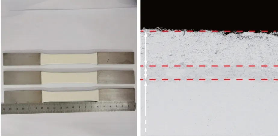
Fig.1 Coating as sprayed (a) Coating sample and (b) Coating system under light microscope
Thermal barrier coatings were prepared on the GH4169 nickel-based superalloy substrate (Ni:49wt%, Fe: 20wt%, Cr: 17wt%, Mo: 5wt%, and Al: 3wt%).The bonding layer was prepared by supersonic flame spraying, and the ceramic layer was prepared by atmospheric plasma spraying.The spraying parameters are shown in Table 1.The sample and section morphology after spraying are shown in Fig.1(a, b), where the ceramic material is 8YSZ (8%Y2O3+ZrO2), and the thickness is 250 μm.The bonding layer materials are NiCoCrAlY and NiCoCrAlYHf,the thickness is 100 μm, the particle size of the powder particles in the bonding layer is 20-70 μm(hereinafter, the coating is referred to as NiCoCrAlY and NiCoCrAlYHf).The high-temperature oxidation behavior of the coating was studied by exposing the coating to a high-temperature environment.The two coatings were placed in a muffle furnace at room temperature (25 ℃), and the temperature was increased to 1 100 ℃ at a rate of 10 ℃/min to perform a constant temperature oxidation experiment.In order to minimize the error of oxidative spalling, all samples were placed in rectangular alumina containers.An electronic balance with a sensitivity of 10-4g was used to weigh the sample in the specified time period and record the data.
2.2 Static load tensile and DIC measurement

Fig.2 Schematic diagram of matrix sample
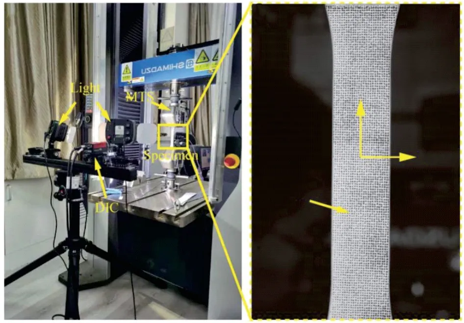
Fig.3 Tensile system and tensile specimen
The tensile substrate sample is shown in Fig.2.The black area in the middle of the sample is the thermal barrier coating.Fig.3(a) shows the stretching system equipped with DIC measuring equipment.Before the coating is stretched, it is necessary to perform artificial gray-scale speckle images on the sample, which is to allow the surface of the ceramic layer to absorb black speckles to perform digital image processing to obtain the strain changes on the coating surface.A roller brush with a spot diameter of about 0.1 mm was used to roll the surface of the ceramic layer once, so as to obtain uniform and uniformly spaced speckles.In Fig.3(b), it can be seen that there are about 9 spots per square millimeter, which fully meets the accuracy requirements in the analysis process.Loading was carried out by controlling the stretching rate at 0.3 mm/min, and the sampling frequency was set at one sample per second.In the coating plane area, theXdirection was consistent with the loading direction, so the strain in this direction was more reasonable as the mechanical performance parameter of the coating.
2.3 Determination of yield strength
The GH4169 matrix was polished, and NiCoCrAlY and NiCoCrAlYHf adhesive layers were sprayed on the matrix with a spray thickness of 3 mm.As shown in Fig.4, wire cutting is used to separate the bonding layer from the coating to obtain an independent bonding layer structure.Then, the two bonded layers were oxidized at high temperature in the same experimental environment.Finally, the universal tensile tester was used to draw the oxidized coating under static load, and the stress and strain curves of the coating were obtained.

Fig.4 Schematic diagram of bonding layer separation
2.4 Performance characterization
After high temperature oxidation, a 10 mm ×10 mm×8 mm oxidized sample was cut from each independent coating, and then mounted, polished, and ultrasonically cleaned to make a sample.The cross section of the sample was sprayed with gold to prevent charge reaction.Field emission scanning electron microscope (FSEM, Zeiss Gemini 300) to observe the morphology.The acceleration voltage was 15 kV.Electron backscatter diffraction(EBSD, Oxford Symmetry) was used to measure the orientation, orientation difference, and grain size of the coating samples.
3 Results
3.1 High temperature oxidation behavior of coating
Due to the conductivity of oxygen ions and the inherent porous structure of the ceramic layer, the generation of TGO is inevitable.The oxygen in the hightemperature gas diffuses to the bonding layer through the ceramic layer, and reacts with Al in the bonding layer to form a layer of dense alumina.After the Al in the bonding layer is consumed completely, it oxidizes with other elements to form spinel, yttrium aluminum garnet and other oxides[12].Finally, a relatively thin layer of thermally grown oxide (TGO) is formed at the interface between the ceramic layer and the bonding layer.Fig.5 is the SEM microscopic morphologies of the coating crosssection, and Fig.5(a) is the cross-sectional morphology of the coating in the sprayed state.The coating and the substrate are mechanically combined, and the coating is tightly combined.Fig.5(b) shows the cross-sectional morphology after high-temperature oxidation.It can be seen that a continuous layer of oxide is formed in the coating, and the thickness of the oxide is about 5 μm.
According to the Wagner’s high-temperature oxidation theory, the high temperature oxidation process of coatings is controlled by the rate of migration of metal and oxygen ions from the bonding layer through the TGO[13].Fig.6 shows the high temperature oxidation kinetic curves of the coating,the oxidative weight gain of the coating is completely determined by the reaction between the bonding layer elements and oxygen.In the whole oxidation stage, the weight gain rate of NiCoCrAlYHf coating is lower than that of NiCoCrAlY coating.
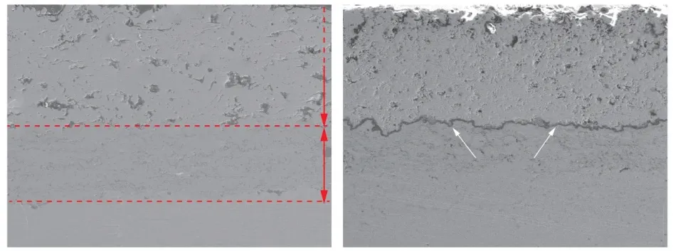
Fig.5 FESEM micrographs of coating cross-section: (a) Unoxidized;(b) Oxidized for 100 h
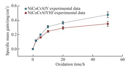
Fig.6 Coating isothermal oxidation kinetic curves
3.2 Yield strength of the bonding layer
The universal stretcher is used for static tensile of the adhesive layer.Fig.7 shows the stress-strain curves of the adhesive layer extracted from the tensiometer,which indicates that the adhesive layer has obvious elastic deformation and plastic deformation stage.The yield loads of the NiCoCrAlYHf and NiCoCrAlY adhesive layers extracted are 8 892 and 7 605 N,respectively.Because the specimen is subjected to only one tensile direction in the process of drawing, it can be used as the principal stress in the process of drawing the coating.Through formula (1):
where, σ is the yield strength,Pthe yield load, andAthe initial cross-sectional area of the sample (3 mm×15 mm).The yield strength of the NiCoCrAlYHf and NiCoCrAlY adhesive layers was calculated to be 197.6 and 169.0 MPa, respectively.It can be seen from the experimental data that the yield strength of rare earth NiCoCrAlYHf coating increased by 28.6 MPa after oxidation.
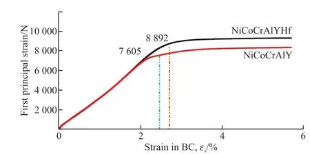
Fig.7 Stress and strain curves of the bonded layer
3.3 Stress evolution characteristics of the matrix
The universal tensile testing machine was used to stretch the experiment, and DIC was used for real-time monitoring of the effective coating area of the standard parts.Fig.8 shows the typical stress-strain curve of the matrix under tension, which presents typical tensile characteristics of ductile metal, including elastic phase and a plastic deformation phase.In the illustration, a,b, c, and d show the representative moments when DIC is detected on the surface of the coating.Point a is in the elastic deformation stage of the substrate, and the stress distribution on the coating surface is uneven.As the loading progresses, the strain of the substrate also increases.As shown in Fig.8(b), the stress in the middle area of the coating increases sharply and the strain changes greatly.When the substrate enters the plastic stage, interface cracks begin to appear on the surface of the coating.As the stress increases, the interface cracks propagate and cause surface cracks, as shown in Fig.8(c).At this time, the stress is concentrated on the edge of the ceramic layer and surface cracks are induced.The surface cracks spread rapidly inside the coating, and the cracks will penetrate the surface of the ceramic layer, as shown in Fig.8(d).It can be seen that the strain of the substrate is consistent with the strain of the coating surface[14].However, the coating without high temperature oxidation is a three-layer structure sample, and the coating becomes a four-layer structure sample after high temperature oxidation.The process of stress transfer from substrate to coating is complex,so it is necessary to study the stress distribution and crack propagation in coating by other methods.
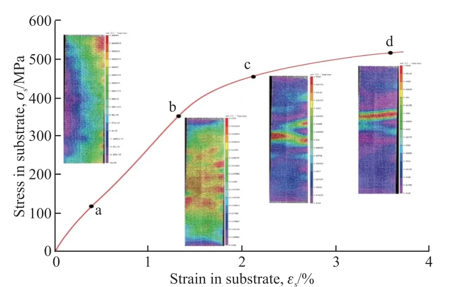
Fig.8 Typical stress-strain curve of the matrix under static tension
3.4 Surface strain of thermal barrier coating
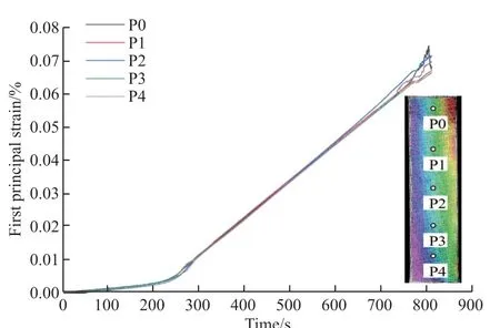
Fig.9 Evolution of principal strain on the surface of thermal barrier coating
In order to better study the stress changes on the coating surface, five points are selected in sequence in the middle area of the coating surface, numbered P0-P4, including the point of maximum absolute value of tensile strain.The first principal strain is extracted from the selected point, which is the tensile strain in the x direction in Fig.3(b), and the relationship between the surface strain of the coating and the loading time is shown in Fig.9.It can be clearly seen from the figure that there is a significant change in the principal stress around 250 s.There are two speeds in the stretching machine: during the stretching process, delamination or cracks in the coating caused stress inconsistency,and the deformation of the coating was inconsistent with the deformation of the substrate; (2) The plastic deformation of the substrate leads to a sudden change in the strain of the coating.However, the tensile stress of the coating maintains a linear change after the sudden change, and there is no fluctuation in the yield stage of the metal material.Therefore, the sudden change of the principal strain on the coating surface is caused by delamination or cracks inside the coating,so the suddenness of the principal strain slope of the coating can be used as the basis for the initiation of internal cracks in the coating[15].

Fig.10 The relationship between surface strain and time of thermal barrier coating after high temperature oxidation
With the above method, with the surface cracks of the sprayed sample as the object, extract the strain curves of the characteristic points where the cracks are initiated, and obtain the relationship between the coating strain and the loading time, as shown in Fig.10.There are two obvious sudden changes in the slope of the curve, which indicates the initiation and propagation of cracks in the coating.For the non-oxidized coating at room temperature, it can be clearly seen that the slope of the coating has abrupt changes at about 275 s.At this time, the abnormality means the initiation of surface cracks.The second abrupt change occurred in about 690 s.At this time, the cracks developed at the interface, which resulted in a greater abrupt change in strain and a large shift in surface speckles.The coating would face the risk of peeling failure.After the coating is oxidized at high temperature, TGO is generated inside the coating, which causes the coating structure to change.It can be seen directly from the figure that the interface cracks of the NiCoCrAlY coating after high temperature oxidation occur earlier than the unoxidized coating.The NiCoCrAlYHf coating has a delay in the appearance of interface cracks.
4 Discussion
4.1 Effect of rare earth doping on coated TGO oxide
The chemical reaction of TGO at high temperature is related to the aluminum concentration in the bonding layer and the oxygen concentration in the ceramic layer.With the progress of high temperature oxidation,the aluminum element in the bonding layer migrates outwards.Its migration during the bonding layer meets Fick’s law of diffusion.The diffusion concentration is related to space and time, and finally forms at the interface of TGO and bonding layer.Concentration gradient of aluminum.The TGO formed during the entire oxidation process is relatively thin, so the diffusion process around the TGO can be simplified to a one-dimensional problem.When the sample is oxidized in a high temperature environment, the migration of aluminum element occurs.Therefore, the aluminum element is a transient process in the migration process,and Fick’s second law can be used to describe the diffusion process over time, as shown in formula (2):
where,Dis the diffusion coefficient, andxthe distance to the interface of TGO and BC.This equation describes the diffusion of aluminum from BC to TGO.Since the TGO layer is only a few microns, the distribution of aluminum can be simplified to a constant and satisfy the law of conservation of mass.The morphology and composition of the coating TGO are further studied.As shown in Fig.11, the FESEM microscopic image and EDS point scanning energy spectrum of the bonding layer after high temperature oxidation of the thermal barrier coating can be seen in Fig.11(a).The TGO layer is thicker than the TGO in Fig.11(b).In the early stage of oxidation of the NiCoCrAlY coating, a large number of Al atoms are consumed and the Al concentration decreases.When the concentration is lower than a certain value, Ni oxides will be formed on the surface of the coating.From the qualitative point scanning of the EDS energy spectrum, it can be concluded that the surface oxide of the coating is Ni-rich and Corich phase, that is, the spinel phase.The formation and growth of the spinel phase in TGO significantly reduces the layered toughness of the coating[16].As the oxidation time increases, the phases in the TGO layer become more complex, and pores are also formed in the TGO layer.Most of these pores are formed in the spinel phase due to the Kirkendall effect.After the pores of the TGO layer are formed, delamination occurs between the TGO and the bonding layer, and long-term high temperature oxidation leads to the delamination of the interface.The addition of rare earth elements in the NiCrAlY coating effectively inhibited the phase transition of Al2O3and occupied Al diffusion channels during high temperature oxidation.It can reduce Ni and Co oxides to diffuse outward through the diffusion channel in TGO.As shown in Fig.11(b), it can be clearly seen that a continuous dense oxide layer is formed on the surface of the bonding layer.Combined with the EDS image, the oxide on the coating surface can be obtained as an Al2O3layer.The dense aluminum oxide layer is the key to improving the ductile fracture of the coating, so the appearance of surface cracks in the coating is delayed.
4.2 The effect of TGO layer oxide on fract ure toughness
-
Due to the non-uniform migration of different elements in the thermal barrier coating system during high temperature oxidation, the entire fracture criterion does not depend on the thickness of TGO, but on more state variables.The most important effect during the entire high-temperature oxidation process is the formation of spinel oxide near the aluminum-poor zone of NiCoCrAlY coating[17].Spinel has lower strength and fracture toughness, and the bonding strength of the bonding layer and TGO layer is reduced.It is related to the migration of aluminum and the formation of other oxides such as spinel.NiCoCrAlY and NiCoCrAlYHf coatings are in the aluminum-rich stage of oxidation,and enough aluminum elements and oxygen elements chemically react to form aluminum oxide.As the oxidation time increases, an aluminum-poor zone is formed near the bonding layer, and further chemical reactions occur to cause the formation of spinel oxides,such as CoAl2O4, Co2CrO4, and more complex Ni and Co oxides.The spinel oxide is loose and has poor adhesion, which reduces the bonding strength of the coating[18].
The presence of spinel oxide affects the mechanical properties of the TBC system.As described in the literature[19], the fracture toughness of the interface is related to the oxidation process dependent on the migration of elements.It is reasonable to assume that the development of spinel oxide is essentially a function of the migration content of aluminum.In general, the fracture toughness of the interface is inversely proportional to the spinel oxide content (ABC).
From the current experimental research, it can be known that since the formation of spinel oxide is proportional to the exposure time, as the cumulative thermal exposure time increases, the fracture toughness decreases with the increase of the spinel content, as shown in the formula (3):
Takekcoas the initial fracture toughness of the interface.It can be seen from the formula that whent=0, the attenuation of aluminum contentABCof BC is 0.As the sample is exposed to high temperature,the migration of aluminum begins, and the fracture toughness decreases.When the interface between the bonding layer and the TGO layer is accumulated by spinel oxide and other unstable oxides, the fracture toughness is close to zero.Under the same exposure,the formation of aluminum oxide in the NiCoCrAlYHf coating is suppressed, and the dense aluminum oxide layer in the coating effectively prevents the formation of spinel oxide.While the high temperature oxidation process is a function of the cumulative exposure timet,the formation of spinel explains the degradation of the mechanical bond strength between BC and TGO in the TBC system, and the fracture toughness represents the mechanical properties of the TBC system.Therefore,after high-temperature oxidation, the surface cracking time of NiCoCrAlY coating is advanced, and the dense aluminum oxide layer in NiCoCrAlYHf is the key to improving the ductile fracture of the coating, so the surface cracking time of the coating is delayed.
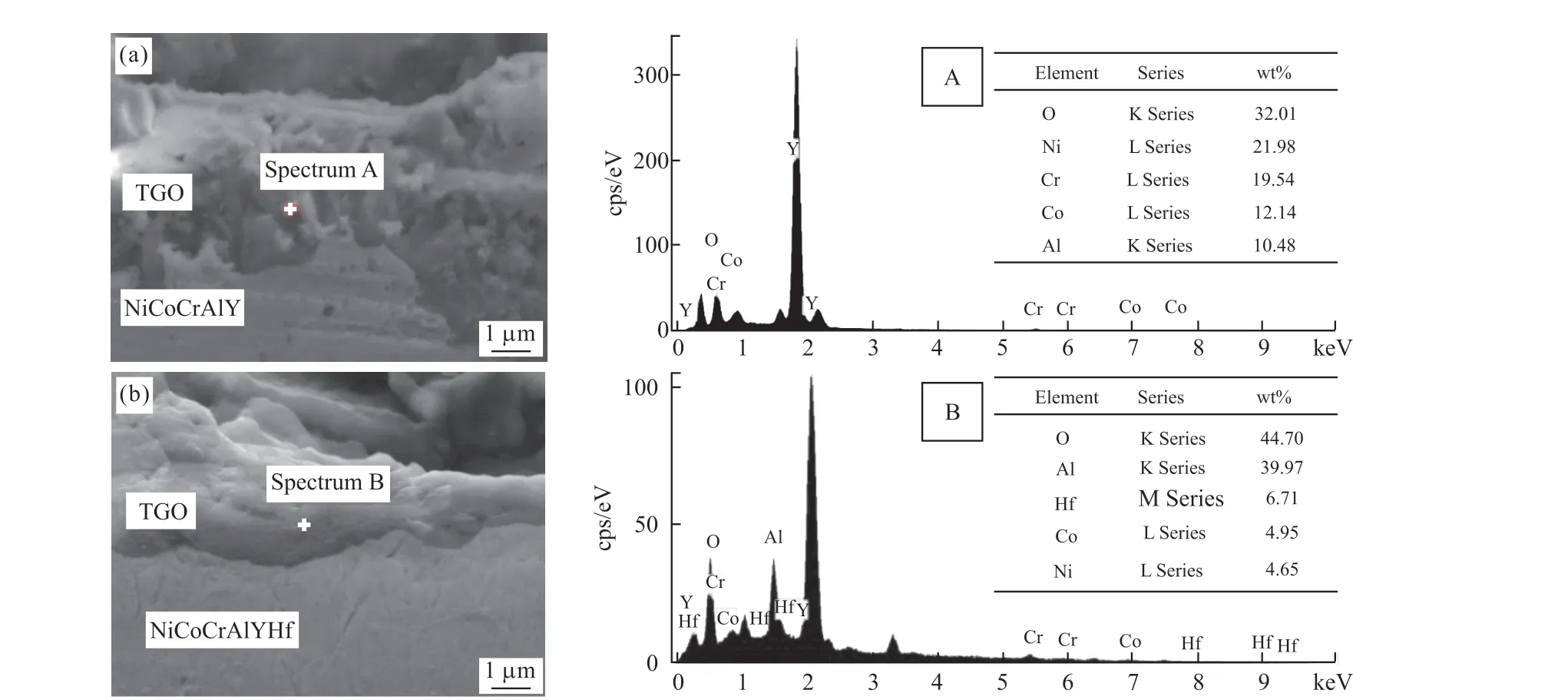
Fig.11 FESEM microscopic images and EDS point scanning energy spectra of the adhesive layer cross-section after high temperature oxidation of the thermal barrier coating: (a)NiCoCrAlY; (b)NiCoCrAlYHf
4.3 Analysis of the mechanism of rare earth doping on the mechanical and thermal stability of coatings
Fig.12 is the electron backscatter image of NiCoCrAlY and NiCoCrAlYHf coatings after hightemperature oxidation for 50 h.The image is processed by Channel 5 software.It can be seen from the figure that the bonding layer is composed of many Al2O3and NiAl3phases of different sizes, and the crystal grains have no obvious orientation distribution.By comparison, it can be seen that the variance of the grain size distribution in the NiCoCrAlY coating is larger,while the grain distribution in the NiCoCrAlYHf coating is more uniform.
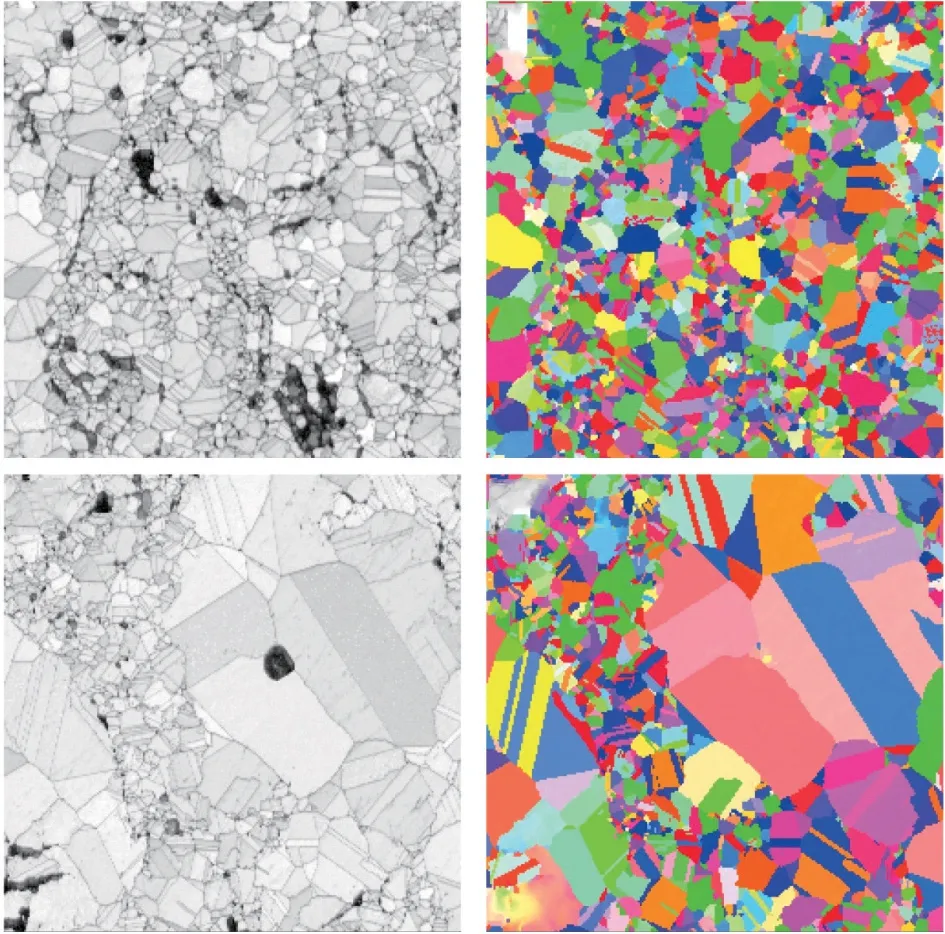
Fig.12 Electron backscatter diffraction patterns after high temperature oxidation of the coating: (a-b) NiCoCrAlYHf;(c-b) NiCoCrAlY
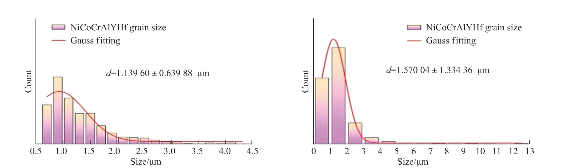
Fig.13 A statistical graphs of the grain orientation of the coating
The grain size in the EBSD image is further counted, and the distribution diagram of the equivalent circle diameter of the grains is drawn as shown in Fig.13.It can be seen intuitively that the grains in the NiCoCrAlYHf coating are concentrated in 0-2 μm, and the size is relatively uniform, with an average size of 1.3396 μm and the grains in the NiCoCrAlY coating are concentrated in 0-3 μm, and with a few grains larger than 10 μm, the average grain size is 1.57004 μm.It can be seen that the crystal grains in the bonding layer are significantly refined after rare earth doping.The fine-grain strengthening is an important factor in the improvement of the mechanical strength of polycrystalline materials.Based on the Orowan strengthening mechanism, it is believed that by hindering the movement of dislocations, it plays an important role in increasing the strength[20].The tensile deformation of the coating in the X direction is jointly dominated by the dislocation slip and the twinning mechanism[21], the density of grain boundaries in fine-grained materials is greater.It is generally believed that the density of dislocations at the grain boundaries is greater than the density of dislocations within the grains.When the material is deformed under the action of external force,the grain slippage is blocked at the grain boundaries,which makes the grain boundaries.And the stress at the place increases, which increases the energy required for the movement of the dislocation, thereby increasing the fracture strength of the material[22].The enhancement effect of the grain boundary on the yield strength can be expressed by Hall-Petch[23], as shown in formula (4):
where,Kgbis the microscopic matrix constant (210 MPa.μm1/2) andDthe average grain size.Calculated from the average size calculated in Fig.13, σgbof NiCoCrAlYHf and NiCoCrAlY are respectively 196.7 and 167.6 MPa.Therefore, it can be seen that the addition of Hf element in the bonding layer increases the value of grain boundary strengthening by 29.1 MPa,thereby improving the yield strength of the coating.
5 Conclusions
I n t h i s p a p e r, S E M, E D S a n d E B S D characterization methods are used to analyze the growth characteristics of the coating.The digital image correlation method is used to monitor the microscopic strain of the thermal barrier coating under static load.And the mechanical properties and damage characteristics of TBCs were analyzed from the microstructure properties of the bonding layer and TGO.The main conclusions are shown as follows:
a) In the high temperature oxidation experiment,the thickness of TGO increases with time, and the thickness of TGO formed by NiCoCrAIYHf is always thinner than that of NiCoCrAIY coating.
b) The NiCoCrAIY and NiCoCrAIYHf coating samples were stretched by universal tensile testing machine The results show that there is no difference in the cracking time of the two coatings at room temperature.After high-temperature oxidation, the time for cracks in the NiCoCrAlY coating is advanced, while the time for cracks in the rare earth-doped coating is delayed.
c) The addition of rare earth elements in the NiCoCrAlY coating effectively inhibited the phase transition of Al2O3and occupied Al diffusion channels during high-temperature oxidation.The dense aluminum oxide layer is the key to improving the ductile fracture of the coating, so the appearance of surface cracks in the coating is delayed.
d) The grain refinement in the bonding layer is remarkable after rare earth doping.The grain distribution in the NiCoCrAlYHf coating is more uniform.The grains are concentrated in 0-2 μm, and the size is relatively uniform, with an average size of 1.3396 μm.The actual value and theoretical value of grain boundary strengthening increased by 28.6 and 29.1 MPa respectively after the addition of Hf element,which is consistent with the practice.Therefore, the yield strength of doped coating is improved, and the crack occurrence time of coating to appear cracks is delayed.
Conflict of interest
All authors declare that there are no competing interests.
杂志排行
Journal of Wuhan University of Technology(Materials Science Edition)的其它文章
- Enhanced Electrochemical Performances of Ni Doped Cr8O21 Cathode Materials for Lithium-ion Batteries
- Design on the Prestressed Concrete Frame Beam-column
- Synthesis and Flocculation of Polyacrylamide with Low Water Absorption for Non-dispersible Underwater Concrete
- Experimental Behavior of Recycled Aggregate Concrete Filled Steel Tubular Columns
- Impact-abrasive Wear Behavior of ZTA and NbC Reinforced Fe60 Matrix Composites
- Synthesis and Characterization of Hollow Strontium Carbonate Pompons by Composite Soft Template Method