Tunable Emission and Energy Transfer of the Novel KY1-x(MoO4)2-y(WO4)y:xLn3+ (Ln3+ = Dy3+, Eu3+, and Tm3+)Single-phase White Luminescence Phosphor for White LEDs
2024-01-03ZHUHaiHEBinHUANGWeigang
ZHU Hai, HE Bin, HUANG Weigang
(1. Department of Oncology, The Third People’s Hospital of Chengdu, Affiliated Hospital of Southwest Jiaotong University & The Second Affiliated Hospital of Chengdu, Chongqing Medical University, Chengdu 610031, China; 2. Medical Research Center, The Third People’s Hospital of Chengdu, Affiliated Hospital of Southwest Jiaotong University & The Second Affiliated Hospital of Chengdu, Chongqing Medical University, Chengdu 610031, China; 3. National Engineering Research Center for Biomaterials, College of Biomedical Materials, Sichuan University,Chengdu 610064, China; 4. College of Materials Science and Engineering, Sichuan University, Chengd 610064, China)
Abstract: The phosphors of KY1-x(MoO4)2-y(WO4)y:xLn3+ (Ln3+ = Tm3+, Dy3+, Eu3+) were synthesized by using a sol-gel method.Then, the crystal structure, luminescence properties, energy transfer, and white emission of the prepared materials were researched.The molar ratio of the anion group on the photoluminescence(PL)emission and excitation intensity were investigated, revealing that the optimum intensity could be obtained by using = 3:1.The optimal Dy3+ doping concentration of KY(MoO4)1.5(WO4)0.5 was obtained.In addition, the color-tunable emissions of Dy3+/Eu3+-codoped KY(MoO4)1.5(WO4)0.5 phosphors were observed because of the effective energy transfer (ET) from Dy3+ to Eu3+ ions.Finally, by doping appropriate concentrations of Tm3+,Dy3+, and Eu3+ and different concentrations of (WO4)2-, white light emitting phosphors KY0.92(WO4)2:0.01Tm3+,0.06Dy3+, 0.01Eu3+ with excellent color-rending properties were obtained.The chromaticity coordinate was calculated as (x = 0.3238, y = 0.3173), closing to the artificial daylight (D65, x = 0.313, y = 0.329) illuminant,and which indicates the potential application of near ultraviolet White light-emitting diodes (WLEDs).
Key words: rare earth; phosphors; white LEDs; energy transfer; sol-gel method
1 Introduction
The WLEDs, as a better substitute for fluorescent lamps and traditional incandescent bulbs, have received widespread attention in the field of display and lighting,and have broad application prospects[1,2].Currently,commercial WLED products usually combine blue InGaN chips with Y3Al5O12:Ce3+yellow luminous phosphors, but this WLED can emit cool white light,which has a high correlated color temperature (CCT is about 7 750 K) and low color rendering index (CRI is about 70-80) with the lack of red light component[3].To overcome the shortage of color render index, another WLED has been proposed by mixing the phosphors(red, green, and blue) on the near-UV chips[4,5].So far,a lot of research has been done on the development of novel WLED phosphors.Whereas, some challenges, for example, realizing high luminescence efficiency, good color stability, and excellent color performance, still exist in WLEDs[6].Based on the above facts, singlephased white light phosphors have been synthesized under the excitation of near ultraviolet light to deal with these problems[7,8].
It is well known that luminescent materials doped Dy3+could exhibit two characteristic radiations of the transition4F9/2→6H15/2and6H13/2correspond to blue and yellow under near-ultraviolet excitation[9,10].However,these luminescent materials own the low CRI due to the lack of red emission components.For the compensation for the red emission component, the red emission center should be introduced into the Dy3+ion-doped luminescence phosphors[11].The rare earth (RE) Eu3+is an excellent red activator duo to its5D0→7FJ(J=1,2, 3, 4) transitions corresponding to the emission of orange and red[12,13].Therefore, good quality white light may be obtained by doping with Dy3+and Eu3+ions into luminescent materials.However, for some molybdate/tungstate host materials, such as, NaLa(MoO4)2:Dy3+,Eu3+[14]and LiLa(MoO4)2: Dy3+, Eu3+[7]phosphors, which show yellow light emission with the not enough blue emission component.So, rare earth Dy3+and Eu3+are introduced in KY(MoO4)2-y(WO4)y, and Tm3+, Dy3+,and Eu3+are introduced in KY(MoO4)2-y(WO4)y.
In this work, the synthesis, characterization,and spectral properties of the novel Eu3+-doped KY(MoO4)2-y(WO4)yred-emitting phosphors were investigated.Meanwhile, the ET in the Dy3+-Eu3+of KY(MoO4)2-y(WO4)yphosphors was investigated in detail.Moreover, Tm3+, Dy3+, and Eu3+co-doped KY(MoO4)2-y(WO4)ysingle-phase white emission phosphors were successfully synthesized by the solgel method.The ET between Dy3+and Eu3+was explored in prepared phosphors.By changing the Eu3+concentration, the position of the chromaticity coordinates was moved from the edge of the white region to the center of the white region.The prepared phosphors were expected to show great application potential in the near UV-excited WLEDs.
2 Experimental
2.1 Synthesis of KY1-x(MoO4)2-y(WO4)y:xLn3+(Ln3+=Tm3+, Dy3+, Eu3+)
The phosphors of KY1-x(MoO4)2-y(WO4)y:xLn3+(Ln3+= Tm3+, Dy3+, Eu3+) were synthesized by using a sol-gel method.The analytical grade H40N10O41W12·xH2O, (NH4)6Mo7O24·4H2O, KNO3,Tm(NO3)3·6H2O, Dy(NO3)3·5H2O, and Eu(NO3)3·6H2O were used as starting materials without further purification.First, using the molecular formula of KY1-x(MoO4)2-y(WO4)y:xLn3+(Ln3+=Tm3+, Dy3+,Eu3+) phosphors, stoichiometric amounts of analytical grade chemicals including KNO3, Tm(NO3)3·6H2O,Dy(NO3)3·5H2O, and Eu(NO3)3·6H2O, were dissolved in deionized (DI) water at 30 ℃ and then stirred it vigorously to obtain a uniform solution.Then, the chelating agent citric acid (CA) and ammonium paratungstate (H40N10O41W12·xH2O) and molybdate((NH4)6Mo7O24·4H2O) were added to the above uniform solution with vigorous stirring for 30 min.After stirring for 30 min, a certain amount of the crosslinking agent Polyethylene glycol (PEG) with the same molar ratio as CA was added under constant stirring.Finally, the above solution was transferred to the oil bath (80 ℃) and stirred for 4 h until a transparent sol was formed.Afterward, the prepared transparent sol was kept at 150 ℃ for 10 h to obtain a dry gel.Subsequently, the dry gels were ground uniformly, and calcined at 300 ℃ for 3 h and 900 ℃ for 3 h in the Muffle furnace.
2.2 Characterization
The phase structure of the prepared phosphors was characterized by using X-ray diffraction (XRD)with Cu Kα radiation (λ = 1.54056 Å), operating at 1°/min in the 10° to 80° (Philips PC-APD, 40 kV, and 40 mA).The PL spectra were measured with the F-4600(Hitachi, Japan) fluorescence spectrophotometer.The Phosphorescence lifetime phosphors were measured by using an F-7000 (Hitachi, Japan) fluorescence spectrophotometer.The CIE chromaticity coordinates were calculated by GoCIE software.The emission spectrum was imported into GoCIE software to obtain the CIE coordinates.
3 Results and discussion
3.1 Crystal structure of KY(MoO4)2-y(WO4)y:Tm3+, Eu3+, Dy3+ phosphors
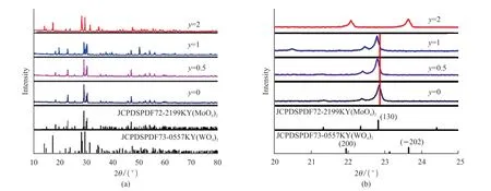
Fig.1 (a) XRD patterns of KY0.92(MoO4)2-y(WO4)y:0.01Tm3+, 0.06Dy3+, 0.01Eu3+ (y = 0, 0.5, 1, and 2) calcined at 900 ℃; (b) The enlarged at 20°-25° of XRD
Fig.1(a) shows the XRD patterns of XRD patterns of KY0.92(MoO4)2-y(WO4)y: 0.01Tm3+, 0.06Dy3+,0.01Eu3+(y= 0, 0.5, 1, and 2) calcined at 900 ℃.Wheny= 0, 0.5, and 1, all the diffraction peaks are consistent with No.72-2199 card peaks, indicating that the samples possessed the pure orthorhombic structure and the phosphors were successfully prepared.In addition, wheny= 2, the diffraction peaks of KY0.92(WO4)2:0.01Tm3+, 0.06Dy3+, 0.01Eu3+pattern are similar to the standard JCPDS cards of KY(WO4)2(No.73-0557) with monoclinic structure.According to Fig.1(b), with the increasing ofy, the peak of (130)shifts to the left because the radius of W6+(0.60 Å) is bigger than Mo6+(0.59 Å).Wheny= 2, the monoclinic structure of KY(WO4)2is observed.
Fig.2 shows the crystal structure diagram of the prepared phosphors with scheelite structure.As we all know, the Mo6+and W6+ions are surrounded by four oxygen neighbors while K+or Y3+site is surrounded by eight oxygen atoms.The ionic radii of Eu3+, Dy3+, and Tm3+with the same CN = 8 corresponding to 1.066,1.027, and 0.994 Å are similar to the radii of Y3+(r=1.019 Å, CN = 8), so the Tm3+, Eu3+, and Dy3+ions are expected to symmetrically replace with Y3+sites by the C2vpoint.

Fig.3 (a)The excitation spectra of KY0.5(MoO4)2-y(WO4)y:0.5Eu3+; (b) The emission of KY0.5(MoO4)2-y(WO4)y:0.5Eu3+ phosphors with different y contents
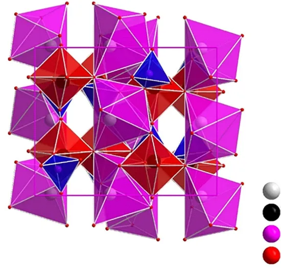
Fig.2 Crystal structure diagram of KY(MoO4)2-y(WO4)y:Eu3+phosphors with scheelite structure
3.2 Luminescent properties of KY0.5
(MoO4)2-y(WO4)y: 0.5Eu3+phosphors
The excitation spectrum (Fig.3(a)) shows a wide band in the 200-350 nm, which is centered on the 270 nm peak and corresponds to the phosphor charge transfer band (CTB).The other peaks of the 350-500 nm wavelength range belong to the Eu3+ions of 4f-4f transitions, which corresponds to7F0→5D4(363 nm),5L7(383 nm),5L6(393 nm),5D3(418 nm) as well as5D2(464 nm) transitions, respectively.Fig.3(b) exhibits the emission spectrum of the KY0.5(MoO4)2-y(WO4)y:0.5Eu3+phosphors, which has some peaks corresponding to the5D0→7F1(592 nm),7F2(613 nm),7F3(650 nm), and7F4(703 nm) transition of Eu3+.In addition, the sublattice structure around activator Eu3+will be somewhat changed due to the similar ionic radius of Mo6+and W6+.Therefore, the ratio of Mo to W is expected to have an impact on the luminescence property[27].The PL intensity with different Mo/W ratios of the phosphors is demonstrated in Fig.3.The peak shapes and peak positions remain similar in the PL spectra of KY0.5(MoO4)2-y(WO4)y:0.5Eu3+contained different Mo/W ratios.However, the PL intensity rises as the value ofyincreases from 0 to 0.5, and the intensity decreases when the value ofycontinuously increases.This result demonstrates that the Mo/W = 3:1 is the best proportion for the host phosphors.
3.3 Luminescent properties of Dy3+ - single doped KY(MoO4)1.5(WO4)0.5 phosphors
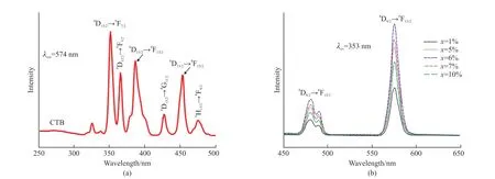
Fig.4 (a) The excitation spectra of KY0.94(MoO4)1.5(WO4)0.5:0.06Dy3+; (b) The emission spectra of KY1-x(MoO4)1.5(WO4)0.5: xDy3+ phosphors with different x contents
Fig.4(a) shows the excitation spectrum of the single Dy3+-doped KY(MoO4)1.5(WO4)0.5phosphors.The wide band (250-320 nm) is the CTB.The other part consists of 353, 365, 386, 427, 453, and 474 nm peaks.These sharp peaks are corresponded to the Dy3+ion (f-f transitions) from the6H15/2(ground state) to6P7/2,6P5/2,4I13/2,4G11/2,4I15/2, and4F9/2(excited states),respectively[28].The corresponding emission spectrum of the KY1-x(MoO4)1.5(WO4)0.5:xDy3+phosphors excited at 353 nm shows two main peaks belonging to blue and yellow wavelength regions.As is shown in Fig.4(b), the peaks at 480 and 490 nm are corresponded to the4F9/2→6H15/2transition, and another emission peak at about 574 nm is assigned to the4F9/2→6H13/2transition[29].In addition.Fig.4(b) shows that with the doping increasing of Dy3+content, the emission intensities reach a maximum atx= 6%, and fall with the continuous increase ofxowing to the concentration quenching.
3.4 Energytransfermechanismof KY(Mo O4)1.5(WO4)0.5:Dy3+,Eu3+ phosphors
Fig.5(a) shows the excitation spectrum of KY1-x(MoO4)1.5(WO4)0.5:0.06Dy3+,xEu3+phosphors with differentxcontents.When monitored at the4F9/2→6H13/2(574 nm) transition, the excitation spectrum is similar to that of a single Dy3+- doped KY(MoO4)1.5(WO4)0.5phosphor (Fig.4(a)).Fig.5(b) shows the emission spectrum of KY1-x(MoO4)1.5(WO4)0.5:0.06Dy3+,xEu3+phosphors with differentxcontents by exciting at 353 nm, which exhibits the three main emission peaks centered at 481, 574, and 613 nm matching to the4F9/2→6H15/2,4F9/2→6H13/2, and5D0→7F2transitions,respectively[30].The results show that when the increase of Eu3+from 0 to 0.03, the PL intensity of Dy3+(574 nm) gets the maximum withx= 3%.It can be attributed that the Eu3+served as a sensitizer and induced energy transition among Dy3+ions with the low doping concentration of Eu3+[31].However, as is shown in Fig.5(c), when the continuously increasing doping Eu3+from 0.03 to 0.1, the emission intensities of Dy3+are slightly reduced while the Eu3+is somewhat enhanced owing to the ET from Dy3+to Eu3+in the KY(MoO4)1.5(WO4)0.5host phosphors[32].
To help explain the paths of the ET mechanism from Dy3+to Eu3+, the excitation spectrum of KY0.9(MoO4)1.5(WO4)0.5:0.1Eu3+and the emission spectrum of KY0.94(MoO4)1.5(WO4)0.5:0.06Dy3+phosphor is shown in Fig.5(d).With 353 nm excitation,the4F9/2→6H15/2transition of Dy3+in emission spectrum has the overlap to the7F0→5D2transition of Eu3+in excitation spectrum.So, there is ET between Dy3+and Eu3+.The ET efficiency (ηT) from Dy3+to Eu3+is also investigated with different doping Eu3+content(Fig.5(e)).A simple calculation of theηTfrom the sensitizer (Dy3+) to the activator (Eu3+) can be expressed according to the following formula[33]:
where, ηETrepresents energy transfer efficiency,ISandIS0are the corresponding intensities of the donor Dy3+emission in the presence and absence of recipient Eu3+, respectively.With the doped Eu3+increasing, the increases gradually up to 73.77 %when the concentration of Eu3+is 10% according to the Fig.5(e).The results show that the is linear to the Eu3+concentration, while the growth rate decreases until the concentration of Eu3+is 10%, illustrating that the ET from Dy3+to Eu3+ions belong to the dipole-dipole interaction and suggesting the energy transfer process tended to saturate[29,31].
The lifetime decay curves of KY1-x(MoO4)1.5(WO4)0.5:0.06Dy3+,xEu3+(x= 3%, 5%, 7%,and 10%) phosphors can be fitted well with a double exponential function because Dy3+and Eu3+can occupy two sites of luminescence center.The lifetime of KY1-x(MoO4)1.5(WO4)0.5:0.06Dy3+,xEu3+(x= 3%, 5%,7%, and 10%) phosphors (Fig.5(f)), show gradually decreasing with the increasing of Eu3+concentration(Fig.5(g)), which is consistent with the tendency of PL intensity of these phosphors (Figs.5(d) and 5(e))and the phenomenon of the ET from Dy3+to Eu3+.The values of CIE parameters, Lifetime, and ET efficiency for these phosphors with the different Eu3+contents are summarized in Table 1.
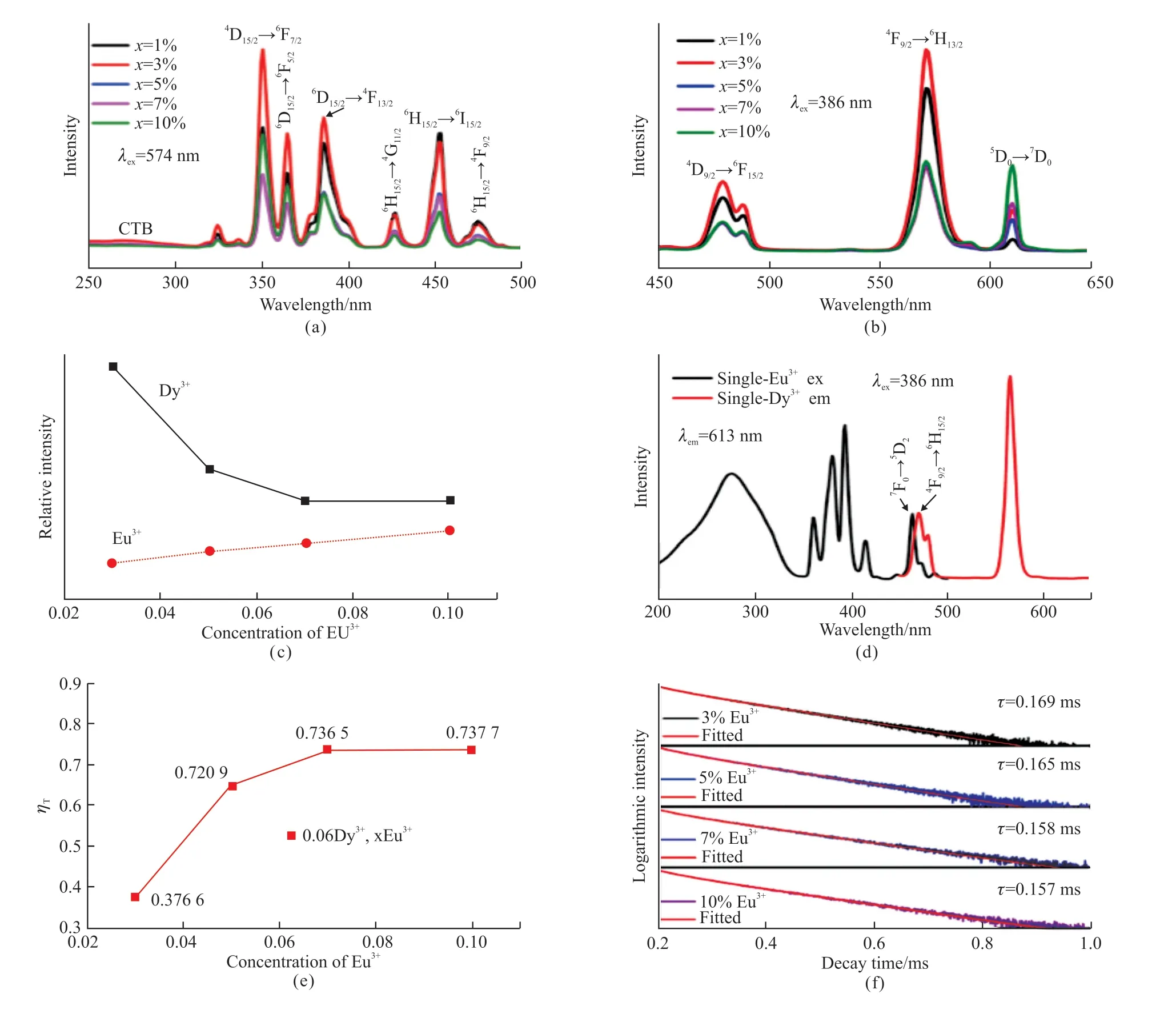
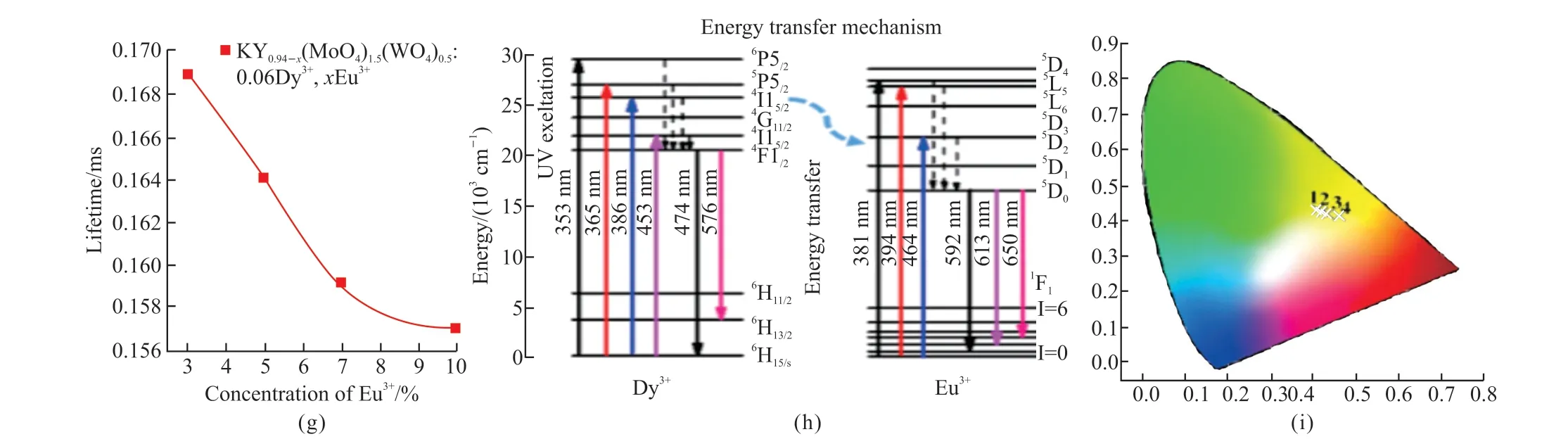
Fig.5 (a) The excitation spectra of KY1-x(MoO4)1.5(WO4)0.5:0.06Dy3+, xEu3+ phosphors with different x content; (b) The emission spectra of KY1-x(MoO4)1.5(WO4)0.5:0.06Dy3+, xEu3+ phosphors with different x contents; (c) The excitation possible energy transfer and emission processes of Dy3+ and Eu3+ ions; (d) The excitation spectrum of single-Eu3+ doped KY0.9(MoO4)1.5(WO4)0.5:0.1Eu3+ phosphor and the emission spectrum of single-Dy3+ doped KY0.94(MoO4)1.5(WO4)0.5:0.06Dy3+ phosphor; (e) The dependence of energy transfer efficiency of KY1-x(MoO4)1.5(WO4)0.5: 0.06Dy3+, xEu3+ phosphors; (f) Decay curves of Dy3+ luminescence in KY1-x(MoO4)1.5(WO4)0.5:0.06Dy3+, xEu3+ (x = 3%, 5%, 5%, and 10%) phosphors excited at 353 nm and monitored at 574 nm; (g) The variation tendency of lifetime KY1-x(MoO4)1.5(WO4)0.5:0.06Dy3+, xEu3+ (x = 3%, 5%, 5%, and 10%) phosphors.; (h) Schematic diagram of the energy transfer process from Dy3+ to Eu3+ in the KY(MoO4)1.5(WO4)0.5:Dy3+, Eu3+ phosphors; (i) The CIE chromaticity coordinates of KY1-x(MoO4)1.5(WO4)0.5:0.06Dy3+, xEu3+ (x = 3%, 5%, 7%, and 10%) phosphors
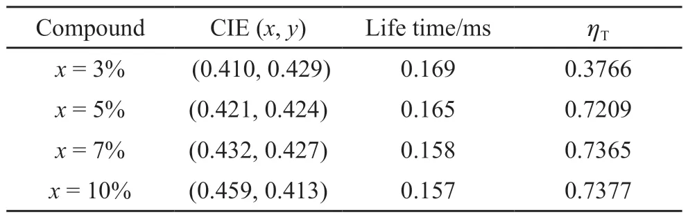
Table 1 The chromaticity coordinates, lifetime and energy transfer efficiency (ηT) of KY1-x(MoO4)1.5(WO4)0.5:0.06Dy3+, xEu3+phosphors excited by 353 nm light
The schematic diagram of the ET from Dy3+to Eu3+is shown in Fig.5(h).Under 353 nm excitation,corresponding to the6H15/2→4I13/2transition of Dy3+,Dy3+ions absorb the energy, and then a part of the energy relaxes the lower energy, and eventually the yellow emissions occur through the4F9/2→6H15/2and4F9/2→6H13/2transitions.Moreover, the ET and emission process are also shown in this diagram.Upon excitation by near-UV light, the electrons are transferred to the excited levels (5L7,5L6, and5D2), then relax to lower energy levels5D0, and finally to the ground state (7F1,7F2, and7F3), respectively.
On the other hand, electrons can transfer a part from4F9/2to the5D0state of Eu3+and then shift to the lower excited energy7F0.So, the ET indeed exists between the Dy3+and Eu3+, which is consistent with Figs.5(d) and 5(e).Hence, this could explain a partial reduction in the PL intensity of Dy3+and a slight increase in the intensity of Eu3+.Moreover, the CIE chromaticity diagram for the emission of Eu3+and Dy3+co-doped KY(MoO4)1.5(WO4)0.5shows yellow emission(Fig.5(i)).
3.5 Tunable luminescence properties of KY0.93-x(MoO4)2-y(WO4)y:0.01Tm3+,0.06Dy3+, xEu3+ phosphors
Fig.6(a) shows the emission spectrum of KY0.99(WO4)2:0.01Tm3+phosphor and Fig.6(b) displays the CIE chromaticity diagram of the Tm3+doped KY0.99(WO4)2:0.01Tm3+phosphor.It clearly shows that the PL color is blue.So, the emission color for the Tm3+, Dy3+, and Eu3+co-doped KY(MoO4)2-y(WO4)ycan be tuned white emission.The emission spectrum of KY0.92(MoO4)2-y(WO4)y:0.01Tm3+, 0.06Dy3+, 0.01Eu3+(y= 0, 0.5, 1, 1.5, and 2) phosphors excited at 359 nm is shown in Fig.7(a).Moreover, Fig.7(b) shows the different trend of PL intensities of Tm3+(453 nm),Dy3+(576 nm) and Eu3+monitored at 615 nm.When the ratio of Mo to W is 3:1, the intensities of the4F9/2→6H13/2transition of Dy3+and the5D0→7F2transition of Eu3+are both found to get to the maximum.This is consistent with the above study.However, when the ratio of Mo to W is 0:2, the intensity of1D2→3F4transition of Tm3+gets the maximum.The reason for this result may be the presence of varying degrees of disorder and the local symmetry of lattice around the Tm3+, which help to improve the intensity of the transition[32].This is consistent with Lin Lin Li’s research[28].Therefore, the changing of Mo/W will have an obvious influence on the intensity of emission peaks of KY0.99(MoO4)2-y(WO4)y:0.01Tm3+, 0.06Dy3+,0.01Eu3+phosphors.Fig.8 shows that the CIE of KY0.94(MoO4)2-y(WO4)y:0.01Tm3+, 0.06Dy3+, 0.01Eu3+(y= 0, 0.5, 1, 1.5, and 2) phosphors, the white emission could be obtained wheny= 2.
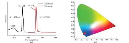
Fig.6 (a) The emission spectra of KY0.99(WO4)2:0.01Tm3+ phosphor after excitation at 359 nm; (b) The CIE chromaticity diagram for the emission spectra of the Tm3+ doped KY0.99(WO4)2:0.01Tm3+ phosphor
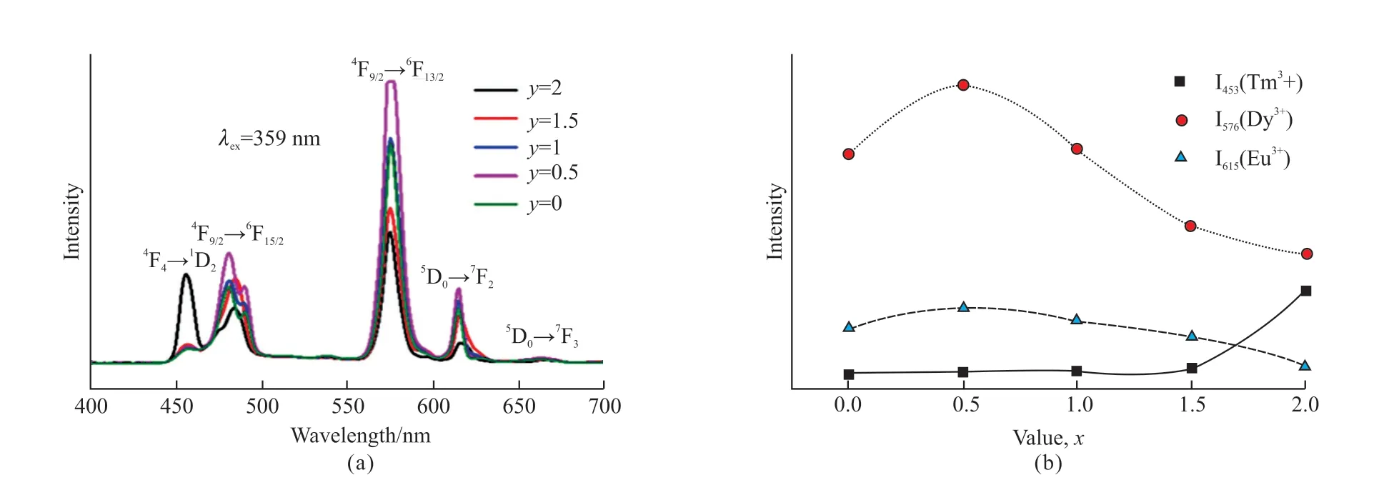
Fig.7 (a) The emission spectra of KY0.94(MoO4)2-y(WO4)y:0.01Tm3+,0.06Dy3+,0.01Eu3+ (y = 0, 0.5, 1 , 1.5, and 2) phosphors under excitation at 359 nm; (b) The variation trend of emission intensities of Tm3+ ions at 453 nm, Dy3+ ions at 576 nm and Eu3+ ions at 615 nm
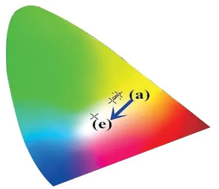
Fig.8 The CIE chromaticity coordinates of KY0.94(MoO4)2-y(WO4)y:0.01Tm3+, 0.06Dy3+, 0.01Eu3+ (y = 0, 0.5, 1, 1.5, and 2)phosphors: (a) y=0; (b) y= 0.5; (c) y = 5; (d) y =1.5; (e) y = 2
Fig.9(a) shows the emission spectrum of KY0.93-x(WO4)2:0.01Tm3+, 0.06Dy3+,xEu3+phosphors, and the reason for the change in PL intensity is related to the energy transfer.Fig.9(b) displays the CIE of these phosphors.With the increase of Eu3+, the position of the CIE changes from the center to the edge of the white area.With the increasing of Eu3+content,the (x,y) coordinates of KY0.93-x(WO4)2:0.01Tm3+,0.06Dy3+,xEu3+phosphors change from (0.3238,0.3173) to (0.3940, 0.3019), which are corresponded to the changing from warm white (5 939 K) to cold white light (2 668 K), indicating that the warm white light can be obtained by tuning the Eu3+concentration(Table 2).Moreover, the CIE atx= 1% is the closest to the CIE white light chromaticity coordinates of the National Television Standards Committee (NTSC)standard (0.33,0.33).These results show that the prepared phosphors could have the advantage of multicolor emission in the visible region under the excitation of a single wavelength light, which is expected to find potential applications in optical display systems and optoelectronic devices[34].
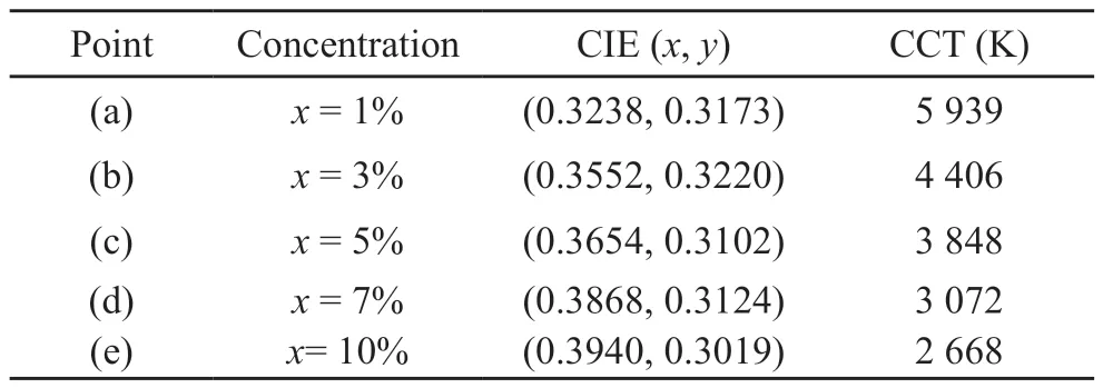
Table 2 CIE color coordinates (x, y) of the KY0.93-x(WO4)2:0.01Tm3+,0.06Dy3+, xEu3+ samples under 359 nm UV excitation
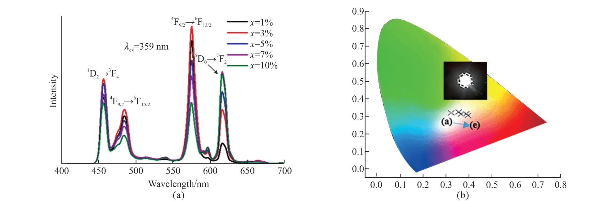
Fig.9 (a) The emission spectra of KY0.93-x(WO4)2:0.01Tm3+, 0.06Dy3+, xEu3+ (x = 1%, 3%, 5%, 7%, and 10%) phosphors; (b) The CIE chromaticity coordinates of these phosphors: (a) x=1%; (b) x= 3%; (c) x = 5%; (d) x =7%; (e) x = 10%
4 Conclusions
In summary, the single-phase white phosphor was successfully synthesized by using the solgel method.The emission spectrum of KY1-x(MoO4)1.5(WO4)0.5:0.06Dy3+,xEu3+phosphors show three main peaks at 490, 574, and 613 nm,corresponding to the4F9/2→6H15/2and6H13/2transitions of Dy3+ions, and the5D0→7F2transition of Eu3+ions, respectively.The emission color of KY0.94-x(MoO4)1.5(WO4)0.5:0.06Dy3+,xEu3+could be shown in yellow, and the energy transfer efficiency increases gradually to 73.77% with the increase of the Eu3+doped concentration.The KY(MoO4)2-y(WO4)y:Tm3+,Dy3+, Eu3+phosphors can be tuned white emitting wheny= 2 under 359 nm excitation.With the increase of Eu3+, the (x,y) coordinates of KY(WO4)2:Tm3+, Dy3+,xEu3+phosphors change systematically from (0.3238,0.3173) to (0.3940, 0.3019), which are corresponded to the change from warm white light to cold white light,indicating that the white phosphors can be obtained by tuning the content of Eu3+.These results indicate that KY0.92(WO4)2:0.01Tm3+, 0.06Dy3+, 0.01Eu3+phosphors have a potential application in WLEDs.
Conflict of interest
All authors declare that there are no competing interests.
杂志排行

Journal of Wuhan University of Technology(Materials Science Edition)的其它文章
- Enhanced Electrochemical Performances of Ni Doped Cr8O21 Cathode Materials for Lithium-ion Batteries
- Design on the Prestressed Concrete Frame Beam-column
- Synthesis and Flocculation of Polyacrylamide with Low Water Absorption for Non-dispersible Underwater Concrete
- Experimental Behavior of Recycled Aggregate Concrete Filled Steel Tubular Columns
- Impact-abrasive Wear Behavior of ZTA and NbC Reinforced Fe60 Matrix Composites
- Synthesis and Characterization of Hollow Strontium Carbonate Pompons by Composite Soft Template Method