Effects of Lay-up Types of Out-of-autoclave Prepregs on Preparation Quality of L-shape Composite Laminates
2021-09-15GONGMingZHANGDaijunZHANGJiayangCHENXiangbao
GONG Ming, ZHANG Daijun, ZHANG Jiayang, CHEN Xiangbao*
(1. Aero Engine Corporation of China Beijing Institute of Aeronautical Materials, Beijing 100095, China; 2.National Key Laboratory of Advanced Composites, Beijing 100095, China)
Abstract: Effects of layer quantities and stacking sequences on L-shape composite manufacturing qualities in using OOA(out-of-autoclave) prepregs were studied. The mechanisms of air evacuated in 5 kinds of lay-ups were revealed by image analysis of cut surfaces and thickness measurements. Results show that air in OOA prepregs is evacuated in two ways. Most of the air is forced out of layers directly by vacuum before air accesses in prepregs closed. Very little entrapped air moves perpendicularly to outer layers under hydrostatic resin pressure. When a laminate contains less than 16 layers, voids can hardly be found in layers.When a laminate contains more than 16 layers, voids cannot be expelled completely during the window of vertical movement. As for stacking sequences, the synergetic effect of slip function and nest function determines the thickness and voids content of laminates. Results show that the average of single layer thickness of unidirectional layers is the lowest, and the average of single layer thickness of quasi-isotropic layers is the highest. The voids content of quasi isotropic is the highest, which is consistent with the theoretical analysis.
Key words: OOA prepregs; L-shape composite laminates; lay-up type
1 Introduction
Curing in industrial autoclaves remains the preferred processing route for the majority of high performance, advanced thermoset composite applications[1,2]. Primary aerospace structures require excellent laminate consolidation, which requests researchers make elaborate analysis and design for composite laminate structures, in order to withstand a large load and complex stress environments. Whereas,using OOA prepregs can produce void-free flat laminates free from the limitations of the autoclave[3].Suitable partially impregnated prepregs is developed to improve air evacuation in out-of-autoclave processes and to gain high quality composite parts[4-6]. Moreover,the complex geometric part needs further investigation,in order to optimize more special structures[7-9]. Lay-up types of laminates should be studied independently to figure out difficulties in processing by using these new materials.
Centea[10]made summary on OOA processing.Brillant and Cauberghs[11]analyses the compression characteristics of L-shaped structures. They develop an analytical model of the compaction of L-shape laminates, in order to better understand the governing mechanisms. But, very little work was performed on effects of lay-ups on L-shape composite laminates based on OOA prepregs[12-15]. Further investigations need to be improved. The effects of lay-ups on composite laminate qualities and mechanisms of formation of void defects were studied.
2 Experimental
2.1 Materials
MTM44-1 OOA prepregs was investigated in this work, in which T300 carbon fibers were partially impregnated by toughened epoxy resin on each side,leaving a dry fiber pathway through the center of the material, as shown in Fig.1. Fiber areal density was 194 g/m2, and resin weight fraction was 32%.
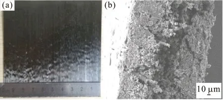
Fig.1 Initial states of MTM44-1 prepreg: (a) Surface condition;(b) Initial resin impregnation
2.2 Laminate manufacture
Convex mold was designed to form L-shape composite laminates (mold radius is 6.4mm). Five layups laminates were prepared and analyzed including[90/0]2s, [90/0]4s, [90/0]8s, [0]16and [0/90/45/-45]2s.Prepregs were cut into 100 mm×100 mm. VBO(vacuum bag only) process by hand lay-up was used, as shown in Fig.2. In the bagging process, laminates were surrounded by sealant tapes, wrapped with woven fiberglass fabric, connecting to the breather. Laminates were covered with a non-perforated release film, to prevent resin from bleeding through surface. A vacuum bag was sealed around tool-laminate set-up and vacuum pressure was applied through a vacuum connector.
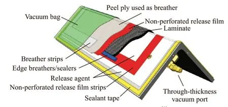
Fig.2 Convex mold structure[1]
Cure cycle was comprised of six steps: 1) debulk at room temperature for 1 hour by vaccum; 2) 1st ramp of 2 ℃/min to 140 ℃; 3) 140 ℃ for 1 hour; 4) 2nd ramp of 2 ℃/min to 180 ℃; 5) 180 ℃ for 2 hour; 6)cool down to room temperature with oven.
2.3 Thickness measurements
Thickness of composite laminates were measured at 11 locations as illustrated in Fig.3.
2.4 Void content measurements
Void contents of composite laminates were estimated by image analysis of cut surfaces. Each image was analyzed by commercially available package Image J.
2.5 Void type characterizations
Void types of composite laminates were characterized by SEM 6010.
3 Results and discussion
3.1 Influence of thickness
3.1.1 Experiment results
Geometric dimension of three thickness laminates were measured as Fig.4. Void contents were calculated by optical microscopy of polished cross-sections in Fig.5.
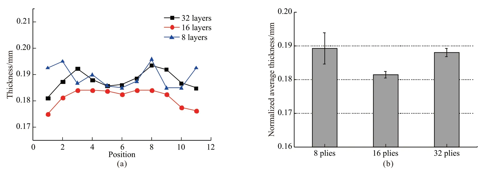
Fig.4 (a)Normalized thickness distribution of three thickness laminates; (b) Average thickness of three thickness laminates
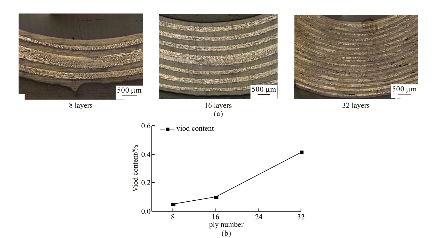
Fig.5 (a) Cross-sections of three thickness laminates manufactured with VBO processing; (b)Porosity of three thickness laminates
Void types in MTM44-1 L-shape laminates were calculated by SEM microscopy and were presented in Fig.6.
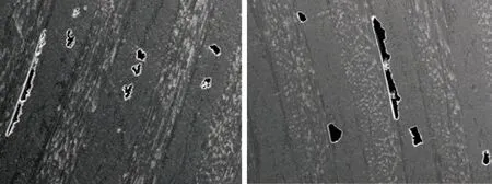
Fig.6 Voids defects of L-shape MTM44-1 composite sample:voids in (a) inter layer and (b) intra layer
3.1.2 Discussion
In OOA process, dry fiber areas are infiltrates by resin at elevated temperature, causing a significant decrease in thickness[16,17]. The free-body diagrams for the compressive stress at the corner is illustrated in Fig.7. Due to prepregs slippage, the surface at tool side got a larger reaction pressure compared to bag side under compaction[18,19]. Therefore, for equilibrium of forces, the reaction pressures at tool side are bigger than the compaction pressures applied on bag side. The laminate radial compressive stress is then higher at the corner in the case of a convex tool. Corner thinning occurs.
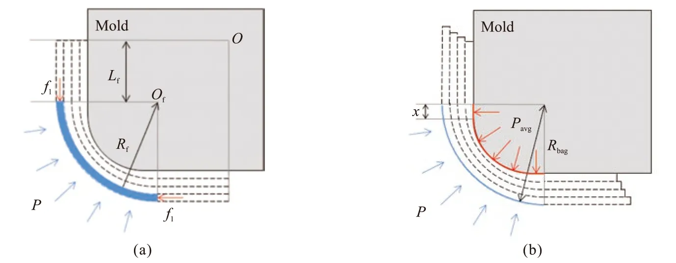
Fig.7 Equilibrium condition of forces in convex molding diagram: (a) Before compaction; (b) After compaction
The phenomenon that corner thicknesses are thinner than both flanges are showed in Fig.4, for three thicknesses laminates. The thinnest position is No.6,and the thickest positions are No.4 and No.8. These results are consistent with the characters of convex mold preparation.
Free-body diagram of the corner section after compaction on convex tool is illustrated in Fig.6. The pressure P is applied on surface at the bag side and the pressure Pavgreacts on surface at the tool side.According to the geometrical factors and pressure balance equation[20], Eq. (1) is obtained.

wheretis the thickness of laminate;c1is the bulk factor of prepreg.
For various values of radius-to-thickness ratio and laminate thickness, the thickness variation at the corner is calculated by solving Eq.(1), withc1=1.2[11].
The predicted thickness curve and the experimental curve are showed in Fig.8. Thickness reductions of laminates are more obvious with thickness increasing. Experimental data trend is similar with the prediction data trend. But numerical values are different.
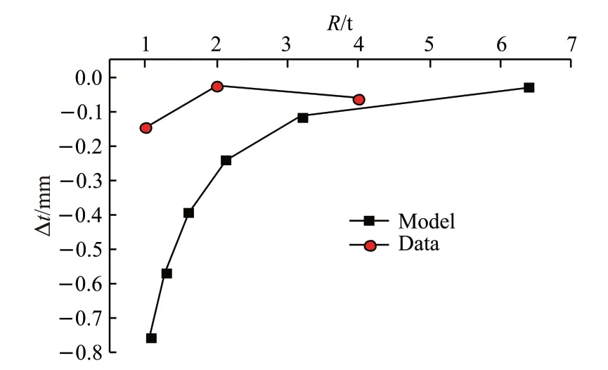
Fig.8 Comparison between experimental and numerical thickness variation curves
The model is based on the assumption that laminates are void-free and each layer is slipped adequately. But the real cure process is impacted by laminate size, sealant tapes placement, lay-up types, temperature, resin viscosity and other factors.As thickness goes thicker, layer slippage effect is weakened.
It can be found in Fig.5 that fiber arrangements are neat, three thickness samples are completely impregnated, and porosities in laminates are below 0.5%. Porosities of 8, 16 layers samples are very low,and porosity of 32 layers sample is relatively high. It can be concluded that with the increase of the thickness of laminates, air evacuation becomes more difficult.Voids distribution of 32 layers laminate is showed in Fig.9. Little voids are detected in 16 layers at tool side. Most voids are distributed in outer 16 layers, as the circle shows. This phenomenon indicates that air migrates at perpendicular direction to the surface under perpendicular direction pressure, as Fig.10 shows.
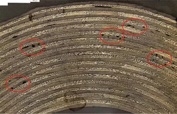
Fig.9 Cross-sections of 32 layers laminate manufactured by VBO process

Fig.10 Air evacuation at corner part: (a) Air emerge; (b) Air migrate
The source of voids defects can be summarized into two categories, as Fig.6 shows. The one is in inter layer. Due to the structure of OOA prepreg, resin in resin-rich area will flow into dry fiber area. In order to evacuate air, 1st dwell temperature shall not reach the lowest viscosity of the resin[21-25], which may cause dry fiber channels to close quickly and to leave voids in inter layer. 1st dwell temperature is designed to reach a relatively low viscosity, in order to maintain dry fiber channels open.
Another one is the voids between layers. The migration of air in direction of thickness is conformed to Darcy’s law. Its migration rate is determined by the synergetic effect of hydrostatic resin pressure and permeability[5,26-30]. For one, the higher hydrostatic resin pressure is, the higher air evacuate rate is.Because high hydrostatic resin pressure has potential in collapsing air bubbles, preventing dissolved air from creating voids and most important, forcing resin impregnate to dry fiber areas and extruding air to outside. It can be explained why void contents of laminates are very low within 16 layers.
For thick parts, inner hydrostatic resin pressure is higher than outer pressure. So, the migrate velocity of air is high in inner layer. In outer layers, hydrostatic pressure decreases to one vacuum pressure, result in a slower migrating rate. At the same time, with the inner air migrating to outer region, the outer air further increases. Therefore, voids defects almost distribute in outer layers.
3.2 Influence of lay-up sequences
3.2.1 Experiment results
Geometric dimension of three lay-up types of laminates were measured as Fig.11.
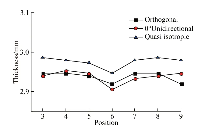
Fig.11 Laminates dimension of three lay-up types
Voids content were calculated by optical microscopy of polished cross-sections and were presented in Fig.12.
3.2.2 Discussion
The corner thickness is thinner than both flanges of [0]16, [90/0]4s, [0/90/45/-45]2slaminates, as Fig.11 shows. As for laminates thickness of three lay-up types,the [0]16is the lowest, [90/0]4sis close to [0]16, and[0/90/45/-45]2sis the highest.
Porosities of [0]16, [90/0]4s, [0/90/45/-45]2slaminates are less than 0.8%, as Fig.12(b) shows.Among them, impregnation quality of [0]16and [90/0]4slaminates are better than [0/90/45/-45]2slaminate.There are no apparent voids in the first two laminates,and fiber arrangement is neat. But some small voids are wrapped in quasi isotropic laminate, as Fig.12(a)shows.
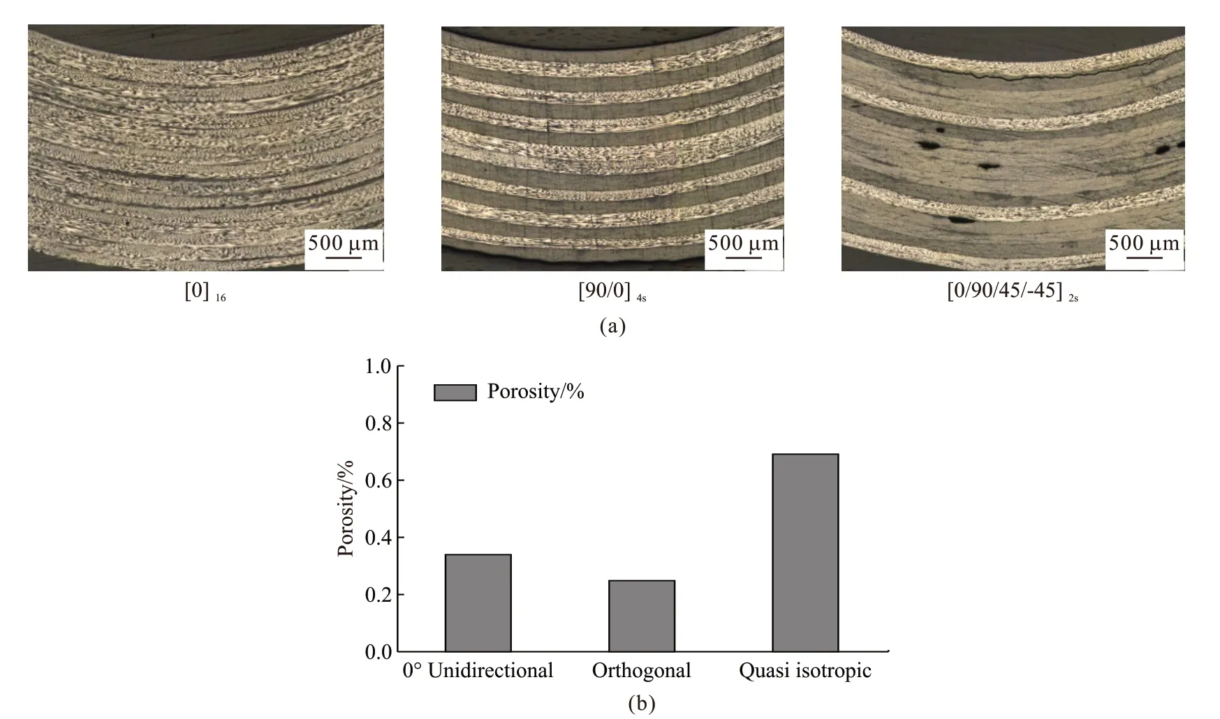
Fig.12 (a) Metallographic pictures of three lay-up types laminates; (b)Porosity of three lay-up types laminates
(1) Porosity analysis
For [0]16laminate:
(a) The fiber bundle in 0° direction is tougher than other directions, and compression deformation of axial sliding is hard, as shown in Fig.13. It makes dry fiber channels stay longer at the 1st dwell temperature,which gives air more time to evacuate.
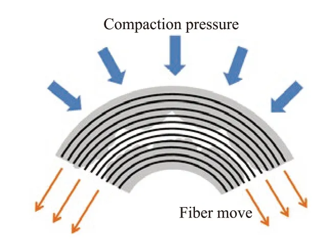
Fig.13 0° direction fiber compression model
(b) Due to the slippage effect, the same direction fibers of adjacent [0]16unidirectional layers slip and nest to each other layers in compression process.Pressures in perpendicular direction is easier to translate to resin, which causes denser compaction of layers and gives air more forces to be evacuated.
For [90/0]4slaminate:
(a) The fiber bundle in 0° direction is tougher than other direction, compression deformation of axial sliding is hard, and dry fiber channels stay longer at 1st dwell temperature.
(b) 90° fiber is easier to slip than other ply directions, as shown in Fig.14, because its slip direction is identical with compression slip direction. Pressures of vacuum translate to resin of [90/0]4sorthogonal layer more quickly, which results in low porosity.
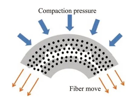
Fig.14 90° direction fiber compression model
For [0/90/45/-45]2slaminate:
The quantity of 0° and 90° layers of quasi isotropic laminate is less than [0]16and [90/0]4slaminates. So, there is less support and slip effects,which causes weaker air evacuations.
(2) Thickness analysis
(a) Due to the slippage function, the same direction fibers of adjacent [0]16unidirectional layers can slip and nest to each other layers. Fiber layers are easier to compress and thickness is the thinnest.
(b) [90/0]4slaminate has no nest effect, but it 90°layers slip deformation is larger than other two. So, its thickness is thinner than [0/90/45/-45]2slaminate.
(c) [0/90/45/-45]2slaminate has no nest effect and less slip deformation. So, its thickness is the thickest.
4 Conclusions
The mechanisms of air evacuated in 5 kinds of lay-up types were revealed. The manufacturing quality of L-shape composite laminates were analyzed. Three main conclusions were summarized as follows:
a) Convex molding deformation model is built according to the convex mold molding structures.Laminate thickness results are consistent with the convex molding model, whose corner thickness is thinner than both flanges.
b) The thickness increase leads to porosity of L-shape composite laminates increase, and the voids mostly in outer layers. The average of single layer thickness of 16 layers laminate is the lowest. Due to the synergetic effect of L-shape structure and processing conditions, 8 layers and 32 layers laminates are higher.Porosities of 8, 16 layers samples are very low, and 32 layers sample porosity is relatively high.
c) Due to nest function of 0° layers and slips function of 90° layers, thickness and porosity of [0]16and [90/0]4slaminate are lower than [0/90/45/-45]2slaminate. Air evacuation ability of quasi isotropic laminate is the weakest.
These results might be helpful for the manufacturing of complex shape composites in using OOA prepregs.
杂志排行
Journal of Wuhan University of Technology(Materials Science Edition)的其它文章
- Poly(dopamine)-assisted Bioactive Coating on the Surface of Porous Poly (Ether Ether Ketone) to Promote Osteogenic Differentiation of rBMSC
- Influence of Heat Treatment on Microstructure and Mechanical Properties of Plasma Sprayed FeCrMoCBY Amorphous Coatings
- Lamella Multiple Grained Structure Making 2205 Duplex Stainless Steel with Superior Strength and Ductility
- Progress in Light-weight High Entropy Alloys
- Synthesis and Characterization of Polyaniline/MgTiO3 Composite with Excellent Thermal and Electrochemical Performance
- Synthesis and Characterization of Hyperbranched Epoxy with Terminal Ally Group and Its Application of Toughen Bismaleimide
