Influence of Heat Treatment on Microstructure and Mechanical Properties of Plasma Sprayed FeCrMoCBY Amorphous Coatings
2021-09-15WULintaoZHOUZehuaDENDYongZHANGXinWANGMiqiWANGZehuaZHANGKaichengYANGGuangheng
WU Lintao, ZHOU Zehua*, DEND Yong, ZHANG Xin, WANG Miqi, WANG Zehua,ZHANG Kaicheng, YANG Guangheng
(1. College of Mechanics and Materials, Hohai University, Nanjing 211100, China; 2. Chengdu Customs Technical Centre, Chengdu 610041,China)
Abstract: The changes of the microstructure and the mechanical properties of FeCrMoCBY amorphous coatings prepared by plasma spraying after heat treatment were investigated. 300, 400, 500 and 600 ℃ were selected as the heat treatment temperature, and the crystallization phenomenon occurred after the heat treatment at 600 ℃. The crystallization products of the coating heat-treated at 600 ℃ were α-Fe and Fe23(C, B)6. Heat treatment was beneficial to the microhardness and the bonding strength of the coatings. The microhardness of the coating heat-treated at 600 ℃ increased obviously, and the strongest bonding strength occurred in the coating heat-treated at 500 ℃. The improvement of the wear resistance of the coatings could attribute to heat treatment as well, and the wear resistance of the coating heat-treated at 600 ℃ was the optimum, compared with the coating heat-treated at 500 ℃.
Key words: amorphous coating; heat treatment; mechanical properties; microstructure
1 Introduction
Fe-based amorphous materials attract an extensive attention because of their excellent mechanical,physical and chemical properties[1-3]. However,the amorphous materials usually exist in form of ribbons or filaments, which limits their application.Correspondingly, compared with those bulk materials,Fe-based amorphous coatings have obvious advantages in protecting workpieces, repairing damaged parts and extending their performances[4-6]. Moreover,plasma spraying process, with a characteristic of a rather cooling rate, is considered as a kind of extremely promising technology on preparing Fe-based amorphous coatings[7-9].
As we know, microstructures including defects,interface bonding, element diffusion and crystallization are closely related to properties of the coatings[10-12].Meanwhile, many researches have revealed that post heat treatment could effectively improve the microstructures of Fe-based amorphous coatings such as promoting element diffusion, releasing stress and forming some nanocrystalline phases[13-15]. Furthermore,heat treatment at a rather low temperature (below crystallization temperature) can improve the bonding of interface, eliminate structural stress and heal cracks[16].For Fe-based amorphous coating, heat treatment at its crystallization temperature is conducive to the precipitation of nanocrystalline, which would greatly change the coating performance[17-20]. During the post heat treatment of amorphous coatings, the junction of the coating and the substrate where lots of metallurgy bonding appeared is greatly changed[21], and the amorphous phase transformed into nanocrystalline[22,23],which could increase their microhardness and wear resistance. However, the abrasive wear resistance of heat-treated coatings is not always much better than that of as-sprayed coatings, because the presence of grains may cause defects such as cracks[24,25].
In this paper, influence of heat treatment on Fe48Cr15Mo14C15B6Y2 (at%) amorphous coatings fabricated by plasma spraying was investigated.Porosity, bonding strength, microhardness and wear resistance of the as-sprayed coating and the heat-treated coatings were examined and compared. Furthermore,the changes of the microstructure and the mechanical properties of FeCrMoCBY amorphous coatings prepared after heat treatment were studied in detail.
2 Experimental
Commercial Fe48Cr15Mo14C15B6Y2 (at%)amorphous powder with the grain size of 100-150 μm was selected as the spraying material[26]. Acetone cleaned and sandblasted Q235 steel was selected as the substrate. PARAIRX 3710 plasma spraying system was utilized to perform spraying process. And the spraying parameters were showed below: plasma current of 649 A, jet distance of 121 mm, primary air pressure of 0.34 MPa, secondary air pressure of 0.52 MPa, carrier air pressure of 0.28 MPa and feeding rate of 22 g/min.After plasma spraying, the coatings were heat-treated in SX2-5-12 electrical resistance furnace at 300, 400,500 and 600 ℃ for 30 min, respectively. And then the coatings were cooled in the furnace.
Microstructure of the coatings was investigated by MV3000 optical microscopy (OM). Porosity of the coatings was evaluated by Image Pro Plus. Phases of the coatings were characterized by X-ray diffraction(XRD) with Cu Kα radiation.
Vickers microhardness of the coatings was determined by HXD-100 microhardness tester under the conditions of the load of 100 g and the duration of 10 s. Abrasive wear test was carried out by MLS-225 abrasion machine. And the rotating speed of runner plus the load were 200 R/min, 100 N, respectively.Bonding strength test was conducted by RGM-4050 electronic universal tester in accordance with ASTM C 633-2001 Standard.
3 Results and discussion
3.1 Microstructure
Fig.1(a) showed the cross-sectional image of the as-sprayed Fe48Cr15Mo14C15B6Y2(at%) coating.Obviously, the coating presented a typical lamellar structure. However, some pores and microcracks existed, which were inevitably determined by the plasma spray process. In general, the junction of the coating and the substrate was glossy and even with a little gap. Although there was a large difference in thermal expansion coefficient between the coating and the substrate, no adhesive coating was considered in our test, which proved that the spraying process was successful[27]. Fig.1 (b) showed the surface image of the coating. It could be seen that there were oblate areas (point A), sputtered particles (point B) and partially melted particles (point C) on the surface.
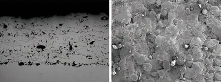
Fig.1 Microstructure of as-sprayed coating: (a) cross-sectional; (b)surface
Fig.2 showed the cross-sectional microstructure of the heat-treated coatings. There was no significant change in the coatings heat-treated at 300 and 400 ℃.Nevertheless, the distribution of pores of the coating heat-treated at 500 ℃ became uniform and the size of pores decreased. But a comparison among the assprayed coating and the coatings heat-treated at 300,400 and 500 ℃ showed that pores slightly increased after 500 ℃ heat treatment. After heat-treated at 600 ℃,the coating had visible modification. Small pores in the coating were reduced. Moreover, the remaining small pores were evenly distributed. And some oxide produced during spraying could be recognized as dark dots and stringers in the microstructure images, in spite of the fact that more large pores appeared in the coating.
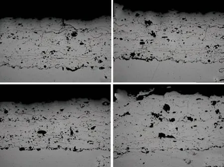
Fig.2 Cross-sectional microstructure of heat-treated coatings:(a)300 ℃; (b)400 ℃; (c)500 ℃; (d)600 ℃
As shown in Fig.2, after heat treatment, the microstructure of bonding part of the coating and the substrate was more compact, especially at 600 ℃. No large pores could be seen at the joint. What’s more, the bonding situation was greatly improved. In general,the bonding between the coating and the substrate was obviously effected by heat treatment.
Fig.3 showed the porosity of the as-sprayed and the heat-treated coatings. The porosity of the assprayed coating was not much different from that of the coatings heat-treated at 300 and 400 ℃. However,it had a little increase after heat-treated at 500 ℃.Moreover, the porosity of the coating heat-treated at 600℃ had a larger increase. And small oxide stringers could be identified. All in all, heat treatment above crystallization temperature would lead to the increase of porosity in the coatings.
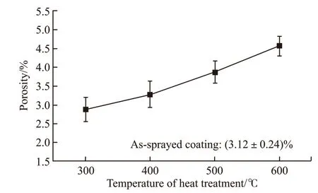
Fig.3 Porosity of as-sprayed and heat-treated coatings
Fig.4 demonstrated the XRD patterns of the assprayed and the heat-treated coatings. Obviously, a typical amorphous diffraction pattern was presented in the as-sprayed, 300, 400 and 500 ℃ coatings. Although the coating heat-treated at 600 ℃ also showed the characteristics of amorphous diffraction, some crystallization peaks could be identified in the pattern,indicating that the coating had partial crystallization in 600 ℃. Through the XRD analysis of the coating at 600 ℃, it could be found that there were α-Fe and Fe23(C, B)6. Despite there were some crystallization peaks besides the coating heat-treated at 600 ℃, the intensities of their phases were too low to be identified.As shown in Fig.5, an exothermic reaction occurred at the temperature 594.5 ℃, confirming the crystallization of the amorphous phase. It could be speculated that element segregation and crystallization would destroy the continuity of amorphous structure, which triggered the appearance of large area pores. On the one hand,the crystallization led to the segregation of elements around the crystalline phase that did not involve in crystallization, which further led to the expansion of pores. On the other hand, pores of the coating far from the crystallization decreased or even disappeared.Therefore, the distribution of pores became uneven.In addition, the amorphous content of the coating decreased when it was heat-treated at a higher temperature. In this case, the amorphous content of the coating at 600 ℃ was 71.48%.
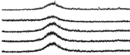
Fig.4 XRD spectrum of as-sprayed and heat-treated coatings
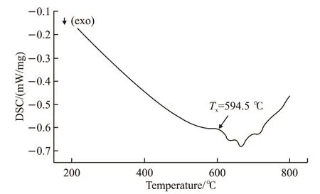
Fig.5 DSC spectrum of amorphous powder
3.2 Microhardness
Fig.6 showed the step hardness of the as-sprayed coating and the heat-treated coatings. As shown in Fig.6 clearly, the difference among the microhardness of the different coatings heat-treated at 300, 400 and 500 ℃ was little. In addition, the hardness of the coating heat-treated at 500 ℃ fluctuated greatly, which was caused by element segregation in the coating. The microhardness of the coating heat-treated at 600 ℃ was much higher than those of the coatings heat-treated at 300, 400 and 500 ℃. It meant that hard crystal phases appeared in this coating during its heat treatment at 600 ℃.
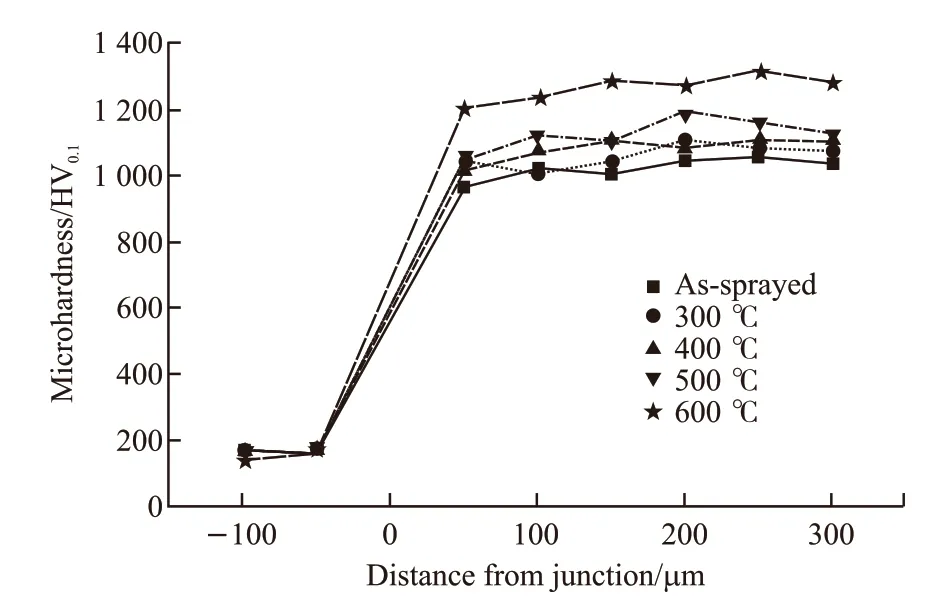
Fig.6 Microhardness of as-sprayed and heat-treated coatings
3.3 Bonding strength
Fig.7 showed the results of bonding strength and Fig.8 showed the macroscopic fracture morphology of the coatings heat-treated at 300 and 600 ℃. As shown in Fig.7, the bonding strength increased after heat treatment. As shown in Fig.8, the fracture location of the coating heat-treated at 300 ℃ was at the joint of the coating and the substrate. The coatings heattreated at 400 ℃ and the as-sprayed coating had the same situation. Nevertheless, the fracture location of the coating heat-treated at 600 ℃ was mainly inside the coating. So was the coating heat-treated at 500 ℃.
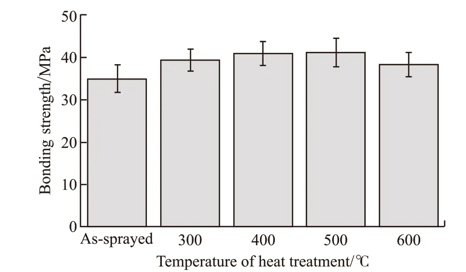
Fig.7 Bonding strength of as-sprayed and heat-treated coatings
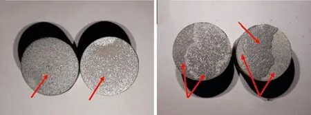
Fig.8 Macroscopic morphology of fracture surface: (a) 300 ℃; (b)600 ℃
Heat treatment at 300 and 400 ℃ was conducive to release the internal stress of the coating. At the same time, elements diffused and distributed evenly. As a result, the internal adhesion of the coatings became higher. After heat-treated at 500 and 600 ℃, the joint between the coating and the substrate was improved.What’s more, an interdiffusion layer formed between the coating and the substrate due to elements diffusion,which enhanced the bonding strength. However, due to the appearance of hard crystal phase in the coating heat-treated at 600 ℃, the amorphous continuous structure was destroyed and large-scale cracks and pores formed. As a result, the bonding strength of the coating heat-treated at 600℃ decreased.
3.4 Wear resistance
Fig.9 showed the effect of heat treatment on the wear mass loss. As shown in Fig.9, the wear amounts of all the coatings after heat treatment were less than that of as-sprayed coating. Since the coating heattreated at 600 ℃ had the highest hardness, its wear mass loss was the smallest. After heat-treated at 300 and 400 ℃, the stress in the coatings was released and the element distribution became more uniform.Therefore, the wear resistance of the coatings was enhanced. The reason for the slight increase of wear mass loss of the coating heat-treated at 500 ℃ was that element segregation occurred in the coating due to its tendency to crystallize, which had some bad effects on the toughness of the coating.
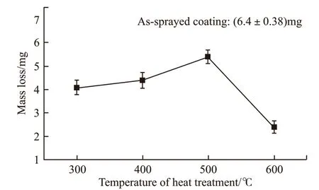
Fig.9 Wear mass loss of as-sprayed and heat-treated coatings
Fig.10(a) showed the worn surface of the assprayed coating. There were many evenly distributed furrows on the worn surface, which was a typical micro cutting morphology. Therefore, micro cutting wear was considered as the primary mechanism of the as-sprayed coating. The surface of the as-sprayed coating was not hard enough to resist the repeated erosive wear of hard grits. Under such circumstance, wear debris generated and surface was damaged.
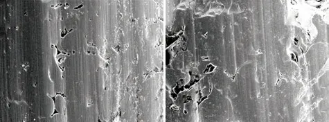
Fig.10 Morphology of as-sprayed and heat-treated coatings after abrasive wear: (a) as-sprayed coating; (b) 600 ℃
Fig.10(b) showed the worn surface of the coating heat-treated at 600 ℃. Only some slight scratches could be seen on the worn surface, but flaking off of tiny lumps occured. Above all, it is suggested that the wear mechanism of the coating heat-treated at 600 ℃was micro fracture. According to the analysis of the bond strength (3.3), there were microcracks inside the coating caused by crystallization. Furthermore, the effect of the wear would promote the growth of the microcracks. When they exceeded the size of minimum failure crack, the lamellae would be peeled off and the coating would be damaged eventually.
4 Conclusions
a) The porosity of the coatings heat-treated at 600℃ increased obviously, compared with other coatings, which was mainly due to crystallization and elements segregation in the coating, and the crystallization products were α-Fe and Fe23(C, B)6;
b) After heat treatment, the microhardness of the coatings increased. The microhardness of the coating heat-treated at 600 ℃ increased obviously, which might be related to the appearance of hard crystal phase.
c) Heat treatment had a significantly positive effect on the bonding strength and wear resistance of the coatings. The coating heat-treated at 500 ℃ showed the strongest bonding strength of 42.16 MPa, and the wear resistance of the coating heat-treated at 600 ℃ was the optimum.
杂志排行
Journal of Wuhan University of Technology(Materials Science Edition)的其它文章
- Mechanical Properties and Microstructure of Al2O3/SiC Composite Ceramics for Solar Heat Absorber
- Effect of Friction Stir Welding on Bulk Metallic Glasses
- Effects of Lay-up Types of Out-of-autoclave Prepregs on Preparation Quality of L-shape Composite Laminates
- Hypereutectic Al-Si Matrix Composites Prepared by In Situ Fe2O3/Al System
- Preparation of Heavyweight Ultra-high Performance Concrete Using Barite Sand and Titanium-rich Heavy Slag Sand
- Effects of Shale and CaO Incorporation on Mechanical Properties and Autogenous Deformation of Early-age Concrete
