Structural Strength Evaluating M ethod of the Azimuth Thruster Propeller Blade
2016-05-15ZHUQuanhuaWEIPengyuYUEYalinHUFanglinLIUDengcheng
ZHU Quan-hua,WEI Peng-yu,YUE Ya-lin,HU Fang-lin,LIU Deng-cheng
(China Ship Scientific Research Center,Wuxi 214082,China)
Structural Strength Evaluating M ethod of the Azimuth Thruster Propeller Blade
ZHU Quan-hua,WEI Peng-yu,YUE Ya-lin,HU Fang-lin,LIU Deng-cheng
(China Ship Scientific Research Center,Wuxi 214082,China)
In order to achieve a precise structural strength evaluation for the azimuth thruster propeller blade,a detailed study is conducted by Computational Fluid Dynamics(CFD)and Finite Element Method(FEM).To solve the problem of unidirectional fluid-structure coupling of the propeller, the method of transferring distributed pressure from fluid field to structure field on the blade surface is mainly discussed.Then a transmission method for fluid pressure on the fluid-structure interface is proposed,and suitable principles of selecting weighting coefficients and element size which impact numerical calculation accuracy are presented.On this basis,strength numerical calculation and safety evaluation of a 5 000 kW azimuth thruster propeller are carried out,and the stress and deformation distribution laws of the propeller are obtained.Finally,the structural strength evaluating method of the azimuth thruster propeller blade is established,which can provide a technical guidance for the design of high-powered azimuth thruster propellers.
azimuth thruster;propeller blade;hydrodynamic forces;pressure transmission; structural strength evaluation
0 Introduction
The azimuth thruster is the core equipment of Dynamic Positioning System for an offshore platform.It can be rotated to any horizontal angle to obtain thrust for the normal operation of the offshore platform.During the long-term service process in marine environment,the azimuth thruster’s propeller mainly withstands the centrifugal force and the complicated hydrodynamic forces.As the substantial increase of engine power,the structural strength of the propeller becomes so prominent that not only the minimum thickness of propeller blades needs to be checked,but also the stress regularity is to be anatomized.Compared to the mature structural strength calculating method,the key to establishing the mechanical model of the propeller is the simulation of external loads,among which the problem of unidirectional fluidstructure coupling is most important.In this paper,the simulation of external loads is achievedby first determining the distribution of fluid pressure on the fluid-structure interface,then exerting the fluid pressure on the propeller surface by a transmission method,and finally exerting the centrifugal force.The key of this process is how to transmit the pressure obtained from the hydrodynamic calculation to the finite element model.
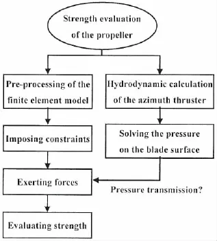
In this paper,a structural strength calculating method of azimuth thruster propeller is developed based on the CFD method and the finite element method,the calculating process is shown in Fig.1.The pressure transmission is implemented by interpolation based on the principle of spatial proximity.In addition, the impact of weighting coefficients of interpolation and finite element size on the numerical calculation accuracy is deeply studied,and some suitable principles of weighting coefficients and element size are presented.On this basis,the strength evaluation of a 5 000 kW azimuth thruster’s propeller is carried out,from which the stress distribution and the safety factor of the blade are obtained.

Fig.1 Process of strength calculation
1 Hydrodynam ic calculation of the azimuth thruster
1.1 Numerical simulation method
In this work,strength calculation of the azimuth thruster is divided into two parts:one is the hydrodynamic calculation;the other is the structural finite element analysis.
The numerical calculating method for hydrodynamic forces is to solve the RANS equation of the three-dimensional incompressible viscous fluid,and the differential equations are discretized by the cell-centered finite volume method.The pressure-velocity coupling is obtained by using the SIMPLE algorithm and pressure interpolating is achieved by using the standard format.In the process of calculation,the momentum,turbulent kinetic energy and turbulent dissipation rate are discretized by the second-order upwind scheme.
The geometric model of the azimuth thruster for hydrodynamic calculation is shown in Fig.2,which includes a propeller,a duct,a pod and a pillar.The propeller is a right-hand one with four blades,and its diameter is 3.85 m.
As is shown in Fig.3,the computational domain in Fluent is a circular cylinder with a radius of 6D,where D is the diameter of the propeller.The inlet boundary is located at 10D upstream of the propeller disk plane,and the outlet boundary is located at 10D downstream of the propeller disk plane.

Fig.3 Diagram of the computational domain
The inlet boundary and cylindrical surface of the computational domain are defined as the velocity inlet,and are given the inflow velocity and direction.The outlet boundary of the computational domain is defined as the pressure outlet,and is given the static pressure.The surface of the thruster is defined as the no-slip body surface[1].
The fluid domain is divided by hybrid grids that the unstructured tetrahedral grid is used in the rotating region of the propeller while the structured hexahedral grid in the other regions. The surface of blades is divided by triangular grids,and the element size is about 20 mm.
1.2 Open water performance prediction
Here the hydrodynamic performance of the azimuth thruster is expressed by the thrust coefficient and the torque coefficient,which are defined by

where TPODis the propulsive force acting upon the thrust.QPROis the torque of the propeller.ρ is the density of water.n and D are the revolution speed and diameter of the propeller,respectively.
In this work,the working condition chosen for evaluation is that the inflow velocity is 2 kns and the revolution speed of the propeller is 180 rmp.

Fig.4 Thrust and torque coefficients at varying rotating angles
The azimuth thruster can be rotated to any horizontal angle.Fig.4 depicts the results of the thrust coefficient and torque coefficient at different rotating angles.The rotating angle is defined as the angle between inflow direction and x-axis direction of the model.If the thruster rotates anticlockwise when looking down from the top,the rotating angle is positive.Results show that the thrust coefficient reaches the peak at the angle of-120°,and the minimum value appears at the angle of 10°.The variation of the torque coefficients is similar with the thrust coefficients.
The hydrodynamic forces acting on the thruster are in the form of fluid pressure.Fig.5 shows the pressure contours of the thruster at the rotating angles of 0°and-120°.Comparing the contours at the two different angles,it is obvious that the surface of propeller blades suffers higher pressure when the rotating angle is-120°.Therefore,it is concluded that the propeller subjects to the maximum hydrodynamic forces when running at the rotating angle of -120°.Strength of the propeller when running in this condition is to be evaluated,and a text named‘pres.dat’,which contains the information of the pressure on the blade surface,is exported.

Fig.5 Pressure contours at the rotating angles of 0°and-120°
2 Pressure transm ission method
2.1 Finite element model
As the propeller is a symmetrical structure,just a single blade is selected for analysis.The finite element model of the blade is shown in Fig.6.In order to reduce the impact of constrains on the result of stress at the root of the blade,a part of hub is added to the blade model and thefixed constrain is imposed on the bottom of the hub.In addition,the root of the blade is rounded with a fillet radius of 60 mm to alleviate the stress concentration.The material of the blade is nickel-aluminum bronze,the mechanical properties of which are shown in Tab.1.

Tab.1 Mechanical properties of nickel-alum inum bronze
The geometric shape of the propeller blade is so complex that its local curvatures and thicknesses change greatly along the radial and tangential directions.In order to better reflect the changing regularity of stress,the element size should be as small as possible.Tetrahedral grid is more adaptable for the blade,and can be automatically generated.Thus,the 10-node tetrahedral grid is used to divide the blade model[2],as is shown in Fig.6.
2.2 Pressure transmission
Pressure on the blade surface is obtained from hydrodynamic calculation in FLUENT, and given as discretized values on the mesh nodes.As the surface mesh nodes in FLUENT and mesh nodes on the surface of the structural finite element model are not one-to-one correspondent,the fluid pressure acting on the finite element model is to be calculated by interpolation[3-5].
Pressure interpolation uses the principle of spatial proximity.As is shown in Fig.7,pressure values of three nearest fluid mesh nodes around the interpolating point are chosen to calculate the pressure value of the interpolating point.
Assume that P is the pressure value of the interpolating point;p1the is nearest fluid mesh node;p2is the second nearest fluid mesh node;p3is the third nearest fluid mesh node.Then,the pressure value of the interpolating point is given as

where a,b and c are the interpolation coefficients,and a+b+c=1.
There are three significant problems to be settled for the fluid pressure transmission[6].First is how to extract the information of mesh nodes under pressure.Second is how to distinguish mesh nodes on the pressure side and the suction side.The last is the interpolation of pressure.

Fig.6 Finite element model of the propeller blade

Fig.7 Diagram of pressure transmission method
In this work,transmission of fluid pressure is completed by the UG software and the selfcompiled interface program.The operation in UG is done by first establishing the geometric model,generating mesh,imparting material properties and imposing constrains;then,exerting evenly distributed pressure which is called‘assumed pressure’on the blade surface and the pressure value can be an arbitrary constant,simultaneously exerting centrifugal force;finally, exporting a text named‘blade.inp’that contains the above finite element information.However,the values of the pressure on surface nodes in this text are not the real ones.The intuitive purpose of the interface program is to replace the incorrect pressure values with real ones in the text named‘pres.dat’obtained from hydrodynamic calculation,and to export a new text named‘newblade.inp’which contains the real pressure information.This new text can be directly imported into ANSYS for numerical calculation.
3 Factors affecting the accuracy of strength calculation
The accuracy of structural strength calculation of propeller blades depends on two key factors:one is the accuracy of pressure transmission,and the other is grid matching performance between models for structural and hydrodynamic calculation.
3.1 Effect of weighting coefficients on pressure transmission
In this paper,pressure transmission is achieved by the interpolating method which is based on the principle of spatial proximity.In order to better control the accuracy of pressure transmission,it is necessary to grasp the effect of weighting coefficients of interpolation.Here four groups of weighting coefficients are chosen for study,which are as follows:

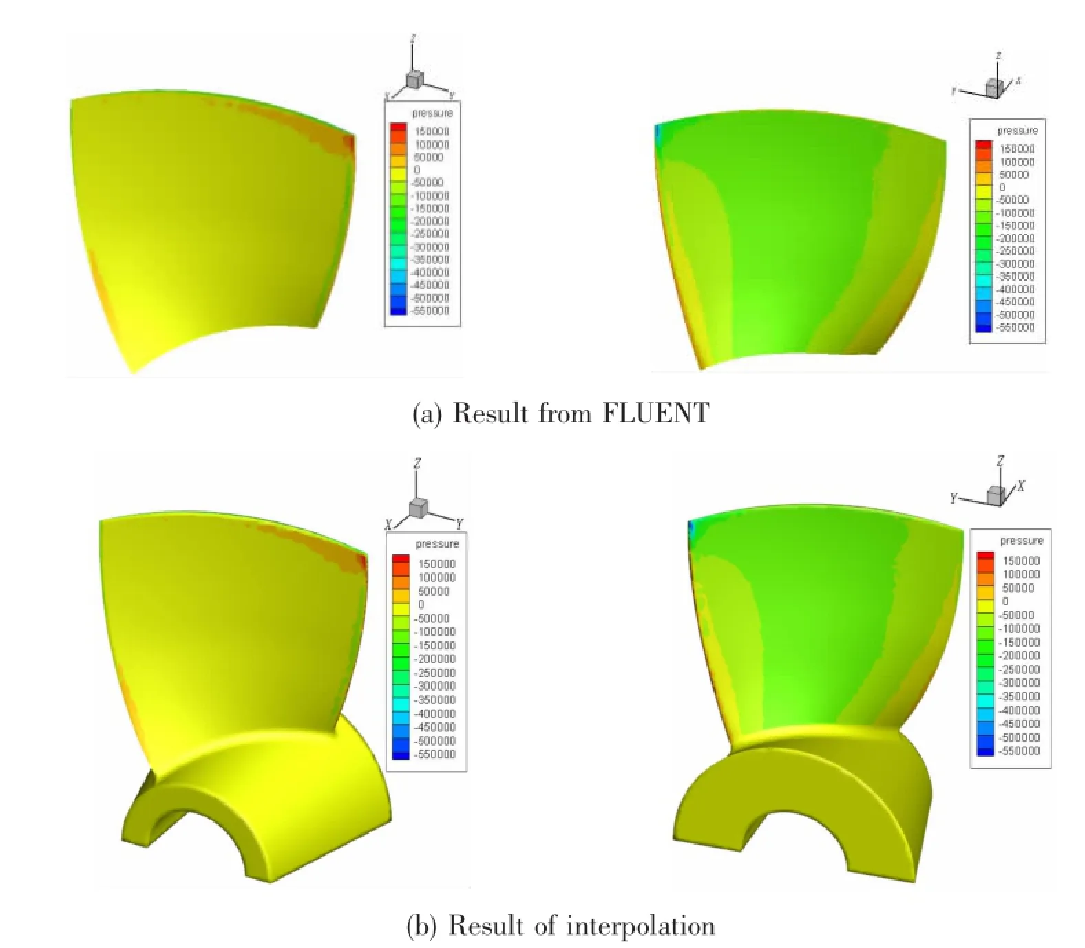
The model is divided with the element size of 28 mm,and the pressure interpolation is done by the interface program.The pressure distribution on the blade surface calculated by FLUENT is shown in Fig.8(a),and the pressure distribution on the finite element model after interpolation(weighting coefficients:a=1.0,b=0.0,c=0.0)is shown in Fig.8(b).Comparing the pressure contours of(a)and(b),it is found that the two results agree well with each other. Therefore,it is concluded that the transmission method proposed in this paper is to be with a high accuracy.The pressure contours of the other three groups of weighting coefficients also agree well with the one obtained from FLUENT,but deeply comparing the pressure values of some mesh nodes,it is found that the result of the weighting coefficients:a=1.0,b=0.0,c=0.0 has the highest accuracy.Tab.2 presents the maximum pressure values on the pressure side and suction side under different weighting coefficients.

Fig.8 Comparison of pressure contours

Tab.2 Maximum pressures under different interpolation coefficients
According to the comparison of the pressure contours and pressure values,the fourth group of interpolation coefficients:a=1.0,b=0.0,c=0.0 is recommended for the principle of spatial proximity.
3.2 Effect of the element size on stress calculation
The working condition for strength calculation is that the inflow velocity is 2 kns,the rotating angle is-120°and the revolution speed of propeller is 180 rmp.According to the finite element method proposed in this paper,the numerical calculation for stress analysis of the blade is done by the ANSYS software.Fig.9 shows the equivalent stress distribution of the blade,of which the element size is 28 mm.As is shown in Fig.9,on the pressure side of the blade,there is a stress concentration region near the leading edge at the radius of 0.8~0.9R,where R is the radius of the propeller.And on the suction side,not only do a stress concentration region exist at the root,but also another stress concentration region exists near the leading edge atthe radius of 0.8~0.9R.

Fig.9 Stress contours of the blade
To ensure the precision of calculation,grids in hydrodynamic calculation and FEM analysis should match as well as possible with each other.Generally,in order to decrease the scale and time of calculation,element size in FEM analysis is smaller than that in hydrodynamic calculation.For determining the impact of grid matching performance between models for structural and hydrodynamic analysis on the accuracy of stress calculation,stress analysis under eight different element sizes are done in this work.These element sizes are 60 mm,50 mm,40 mm,36 mm,30 mm,28 mm,24 mm and 20 mm,respectively,which are chosen based on the element size of 20 mm in FLEUNT.Results of stress calculation under different element sizes present the similar regularity of stress gradients and stress concentration regions,as shown in Fig.9.However,the maximum stresses on the concentration regions differ from each other.Tab.3 lists the concentration regions and the maximum stress values under different element sizes.

Tab.3 Com parison of maximum stresses under different element sizes
The stress concentration factor is given as

where σmaxand σnare the maximum stress and the mean stress of the stress concentration region,respectively.
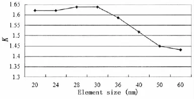
The mean stress of the root on the suction side is σn=58 MPa,which is calculated by the cantilever beam method[7].According to Eq.(3),the stress concentration factors under the different element sizes are calculated and presented in Fig.10.As can be seen from the figure,the stress concentration factor increases with the decrease of element size,and tends to be a stable value when the element size is less than 30 mm.
After comparing the stress contours,positions and values of the maximum stress and the stress concentration factors under different element sizes,it is concluded that when the element size in FEM analysis is 1.0~1.5 times of that in hydrodynamic calculation,the grids match well and the stress calculation is to be with a high accuracy.

Fig.10 Comparison of stress concentration factors
4 Strength evaluation of azimuth thruster propeller blades
When checking the structural strength,the maximum equivalent stress of the structure is compared with the allowable stress of the material.The equivalent stress of a blade node is defined as follows:

where σ1,σ2and σ3are the principal stresses in three directions,respectively. The strength safety factor of propeller blades is expressed as:

where σbis the ultimate strength of the material and σe,maxis the maximum equivalent stress.
Strength numerical calculation and safety evaluation of the 5 000 kW azimuth thruster propeller are carried out according to the above studies,in which the weighting coefficients is a=1.0,b=0.0,c=0.0 and the finite element size is 30 mm.The stress and strain contours of the blade are shown in Fig.11.It can be seen that the maximum equivalent stress of the blade is about 100 MPa,and the deformation distribution of the blade is consistent with the characteristics of the cantilever beam.
Therefore,when running in the selected working condition(Inflow velocity:2 kns,rotating angle:-120°,revolution speed of the propeller:180 rmp),the maximum equivalent stress of the blade is σe,max=100 MPa.According to Eq.(5),the safety factor of the blade is Kb=6.2, which is smaller than that recommended by the rules.This result should be taken seriously in design.

Fig.11 Stress and deformation contours of the blade
5 Conclusions
A pressure transmission method which transfers distributed pressure from fluid field to structure field is put forward to solve the problem of unidirectional fluid-structure coupling of the high-powered azimuth thruster propeller.Then through detailed research about weighting coefficients and element size which impact numerical calculation accuracy,the suitable principles of selecting weighting coefficients and element size are presented.Based on the above research results,the strength numerical calculation and safety evaluation of a 5 000 kW azimuth thruster propeller are carried out,and the stress and deformation distribution laws of the blade are obtained.The results show that the safety factor of blades proves to be small,so the blade structure should be paid more attention in the design process.On the whole,the structural strength evaluating method of the azimuth thruster propeller blade is established,which can provide technical guidance for the design of high-powered azimuth thruster propellers.
[1]Guo Chunyu,Yang Chenjun,MA Ning.RANS simulation of podded propulsor performances in straight forward motion [J].China Ocean Engineering,2008,22(4):663-674.
[2]Qian Weidong,Wu Chengcai,Len Wenhao,et al.Research on automatic geometric modeling and meshing for marine propellers[J].Ship Science and Technology,2011,33(3):39-43.
[3]Li Jianbo,Wang Yongsheng,Sun Cunlou.Stress analysis of highly skewed propeller blades[J].Shipbuilding of China, 2009,50(4):1-6.
[4]Wang Hong,Zeng Zhiwei,Zeng Zhibo.Strength checking method of controllable pitch propeller blades based on numerical calculation[J].Chinese Journal of Ship Research,2014,9(5):53-59.
[5]Wang Xuefeng,Li Feng,Zhou Wei,et al.Research on grid interpolation method of fluid-structure coupling[J].Journal of Ship Mechanics,2009(4):571-578.
[6]Hu Fanglin,Sheng Zhenguo,Liu Xiaolong.Analysis method of fluid-structure interaction for composite blades of wind turbine[J].Acta Energiae Solaris Sinica,2014,10:015.
[7]Huang Yi,Xu Hui,Jiang Zhifang.Strength analysis of highly-skewed propeller[J].Chinese Journal of Ship Research, 2010,5(5):44-48.
全回转推进器螺旋桨桨叶结构强度评估方法
朱全华,韦朋余,岳亚霖,胡芳琳,刘登成
(中国船舶科学研究中心,江苏无锡214082)
为了解决全回转推进器螺旋桨的单向流固耦合问题,实现螺旋桨桨叶结构强度精确评估,文章基于计算流体力学和有限元法开展了螺旋桨桨叶的结构强度计算方法研究,重点探讨了桨叶表面随机分布压力从流体域到固体域的转换技术。在此基础上,文中提出了桨叶固液交界面上水动力载荷的转换方法,详细研究了插值加权系数和有限元网格尺寸对桨叶结构强度计算精度的影响规律,给出了适用于桨叶强度评估的插值加权系数和单元网格尺寸选取原则。最后,该文以5 000 kW级全回转推进器螺旋桨为例,开展了桨叶结构强度数值计算和安全评估,获得了桨叶的应力和变形分布规律,整体上建立了全回转推进器螺旋桨桨叶结构强度评估方法,可为大功率全回转推进器螺旋桨设计提供借鉴和参考。
全回转推进器;螺旋桨桨叶;水动力载荷;表面压力转换;结构强度评估
U661.4
A
朱全华(1991-),男,中国船舶科学研究中心硕士研究生;韦朋余(1982-),男,中国船舶科学研究中心高级工程师;岳亚霖(1964-),男,中国船舶科学研究中心研究员;刘登成(1982-),男,中国船舶科学研究中心高级工程师;胡芳琳(1981-),女,中国船舶科学研究中心高级工程师。
U661.4
A
10.3969/j.issn.1007-7294.2016.09.007
1007-7294(2016)09-1160-11
Received date:2016-06-01
Foundation item:Supported by the Major State Basic Research Development Program of China(973 Program, No.2014CB046706)and Jiangsu Key Laboratory of Green Ship Technology
Biography:ZHU Quan-hua(1991-),male,master student of CSSRC,E-mail:951829290@qq.com; WEI Peng-yu(1982-),male,senior engineer.
猜你喜欢
杂志排行
船舶力学的其它文章
- Recent Progress in Hydrodynam ic M odel Test for Two Floating Bodies at Close Proxim ity in W aves
- Numerical Analysis of Load-noise of a Highly-skewed Propeller behind Subm arine
- Comparison of Different Finite Element Modeling M ethods for the Soil-Pile Interaction of Jack-up Platform
- Vibration due to Propeller-Shaft-Hull Coupling of a SWATH
- Application of Inertia Relief in the Prediction of W elding Deformation for Large Complex Structures
- Dynam ic Pre-ultim ate Strength Evaluation of Containership based on a 2D M odified Hydroelasticity M ethod in Extrem e W aves
