Vibration due to Propeller-Shaft-Hull Coupling of a SWATH
2016-05-15XIONGChenxiYINXuewenDUANYong
XIONG Chen-xi,YIN Xue-wen,DUAN Yong
(National Key Library on Ship Vibration and Noise,China Ship Scientific Research Center,Wuxi 214082,China)
Vibration due to Propeller-Shaft-Hull Coupling of a SWATH
XIONG Chen-xi,YIN Xue-wen,DUAN Yong
(National Key Library on Ship Vibration and Noise,China Ship Scientific Research Center,Wuxi 214082,China)
Longitudinal vibrational characteristics of a Small Waterplane Area Twin Hull(SWATH) ship due to propeller-shaft-hull structure coupling subject to broadband forces on the propeller are investigated.An integrated vibro-acoustic numerical model comprised of the propellers,shafts and ship structures,as well as the entrained sound fluid is developed.Through experiments,measured data agree well with numerical results.Based on this numerical model,the vibration characteristics of the SWATH due to propeller-shaft-hull structure coupling are analyzed.The numerical results show that propeller-shaft-hull coupling can result in the dynamic magnification effect at the first and second longitudinal resonance frequencies of the shaft.Moreover,when the deformation of propellers is taken into account,the similar dynamic magnification is found at certain resonance frequencies of the blades.Such modes for the shaft,the propeller,and their coupling generally exist in low frequency range,so that the dynamic magnification of propeller forces can easily lead to excessive structural vibration and sound radiation.
SWATH;propeller-shaft-hull coupling vibration;coupled acoustic-structural analysis;acoustic infinite elements
0 Introduction
When travelling in unsteady flows,the blades of the propeller are subjected to turbulence pulsation pressure,which is stochastic,and reasonably possesses continuous excitation spectra in frequency domain,namely,low frequency broadband spectra[1].Such loadings can excite the ship hull via propeller-shaft mounting systems,consequently,low frequency vibration and sound radiation are produced,which is generally termed as propeller-shaft-ship hull coupling sound radiation[2].Recent study work shows that,at low travelling speed,the coupling among propeller,shaft,and ship hull contributes significantly in the total sound radiation level,within which the coupled dynamic characteristics of the propeller,the shaft systems,and the ship hull structures,as well as their individual dynamic characteristics,are embedded[3-4].Generally,the transverse components of the low frequency broadband excitation forces are only 1/3 of the longitudinal components in magnitude[5].Since the response transfer functions from the trans-verse and longitudinal excitation forces to the sound radiation are in similar magnitude level, the sound radiation due to transverse forces is relatively low.Hence,in this paper,our attention is mainly focused on longitudinal propeller broadband excitation forces that induce the vibration coupling among propeller,shaft systems,and ship hull,and the subsequent sound radiation as well.
In this paper,an integrated vibro-acoustic numerical model for a SWATH ship comprised of the propellers,shafts,ship structures,as well as the entrained sound fluid and the free surface,is developed.Through experiments,measured data for the vibration and sound radiation of the SWATH agree well with numerical results,which partially validate our numerical model.Based on this numerical method,longitudinal vibration characteristics of propeller-shafthull coupling system excited by broadband forces on propellers are analyzed.
1 Numerical modeling
1.1 Hull structure model developement
Shown in Fig.1 is the schematic structure of a SWATH with the dimension of L in length,0.4 L in width,and 0.31 L in height,and with a load draugh of 0.1 L.It consists two submerging objects,two supporting connections,and several cabins on four decks.Each submerging object has a propulsion system with a propeller driven by a motor.
A vibro-acoustic finite element model for the hull structure is developed,which is shown in Fig.2.Plate type elements are employed for the decks,the ship hull,the walls,the bulkheads,and the machinery bases.Beam type elements are employed for the axial and transverse stiffeners,ribs,and pillars.For sake of numerical efficiency,onboard equipments and machinery are simplified as mass type elements.The mesh size is carefully designed so as to make sure at least 6 meshes exist within the bending wavelength.
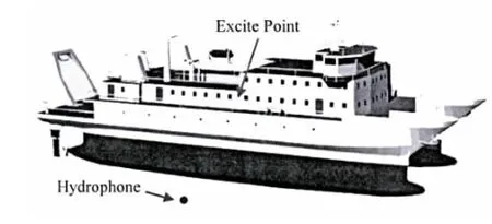
Fig.1 Deployment of exciting point and hydrophone in site experiment
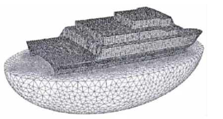
Fig.2 The hull structure vibro-acoustic model
Since the ship hull is surrounded by the fluid below the water surface,the coupling between them should be taken into account.In addition,the sound radiation due to vibrating ship hulls is one of our major concerns.Acoustic finite type elements are assigned to the fluid domain,and the fluid-structure coupling condition is enforced by bonding the displacement degrees of freedom for the fluid and ship hull at their interface.Besides,in order to model the infinite fluid,infinite acoustic elements are assigned onto the exterior surface of fluid domainshown in Fig.2.In the case of more complex sound field,infinite acoustic element algorithm has better precision than the equivalent impedance type boundary conditions.To model the free water surface,equivalent impedance type boundary condition is enforced onto the water surface,to which the air impedance property is assigned.Since the acoustic finite element has excellent precision,the dimension of the fluid domain can be reduced for sake of computation efficiency.By balancing the computer capabilities,computation precision,and simulation objectives,the fluid domain for the acoustic finite elements is designed as an ellipsoid that has 1.3 L and 0.67 L for the long and short axis respectively.The mesh size of the surface that contacts the hull is the same as the hull structure,and the mesh size of the infinite domain is relatively large.
1.2 Propeller-shafting model developement
Eventually,the vibro-acoustic model of the SWATH hull is developed,which accounts for the fluid-structure coupling,infinite acoustic field,and the free water surface as well.To considering the propeller-shafting system,a submodel is developed which is illustrated in Fig.3.

Fig.3 Propeller-shafting system
The total length of the shafting is 0.29 L,which is comprised of stern shaft,middle shaft, thrust shaft,couplings and flexible coupling.The shafts are supported on the hull through aft sterntube bearing,forward sterntube bearing,middle bearing and thrust bearing.The propeller has 6 blades and 0.044 L in diameter.The inner face of propeller’s hub is rigidly connected to the shaft.Except the thrust bearing,the axial constraints to the shaft from other bearings are ignored[6].
The propellers are specified with quadratic 3D solid elements,the shafts are modelled as rod elements,and all shaft bearings except the thrust bearing are simplified as horizontal springs and vertical springs.Thrust bearing is modelled as a horizontal spring,a vertical spring and a longitudinal spring,and the stiffness of the longitudinal spring is prescribed to be 9e8 N/m, which denotes the stiffness of thrust bearing’s oil film.Thrust pads,couplings and flexible coupling are represented by point mass.
In order to fully consider the coupling between the propeller and the shaft,the shaft and the hull,the hull and surrounding fluid,the propeller and the exterior fluid,the above hull structure model and propeller-shafting model are incorparated into an integrated vibro-acoustic numerical model of a SWATH shown in Fig.4.

Fig.4 Propeller-shaft-hull coupling vibro-acoustic model of a SWATH
As the contact area of the shaft and the fluid is relatively small,the interaction between them can be ignored.On the other hand,the coupled effect of the propellers and the fluid must be taken into account[7].The acoustic domain around the hull shown in Fig.2 is exported to propeller-shaft-hull coupling vibro-acoustic model,and the surfaces of propeller’s blades are also coupled with surrounding fluid,so the fluid loading of the hull and propellers are both included in the intergrated model.
2 Experimental verification of numerical results
In vibration and acoustic tests for this SWATH ship,we measured the sound radiation at moored conidtion as a force hammer knocked on the deck;we also measured the vibration of shafting and its adjacent cabins when the ship sailed in the sea.In this section,the comparison of test and numerical results for the underwater sound pressure is made to verify the acoustic computation capability of our numerical model.The comparison of shaft vibration when the ship sails in the sea is also made to verify the shafting vibration computation capability of the model.
In the experiment of knocking excition,the exciting point and the hydrophone are deployed as shown in Fig.1.The sound transfer function is defined as the sound pressure by exciting force of 1.0 N,and the comparison of the experimental data and numerical results is shown in Fig. 5(a),where f/fpis the nondimensional frequency(fpis the reference frequency),and the sound pressure level is expressed in terms of 20log (p/p0),p0is reference sound pressure.From Fig.5 (a),we can find that in low frequency domain,the experimental data and the numerical results are in good agreement,which demonstrates that our vibro-acoustic numerical model can meet the precision requirements for sound radiation analysis in low frequency domain.
When the ship was sailing in the sea,the acceleration sensor was installed at the point A2 shown in Fig.3,which is located on the thrust shaft,and the rotation speed of shaft is 10 fp(r/ min),viz.blade-passing frequency is fp(Hz).The test results of longitudinal acceleration at point A2 are shown in Fig.5(b),the horizontal axis denotes nondimensional frequency f/fp,thevertical axis is vibration level 20log (a/p0),p0is also the reference acceleration.Now we assume that when the ship sails in the water,the longitudinal vibration at point A2 in low frequency range is totally induced by the longitudinal component of forces on propellers,so we can compare the measured data with the numerical results.In the numerical model,the longitudinal harmonic force is applied to each blade,and the amplitude-frequency curve of the force is given by the semi-empirical formula of low frequency range broadband force on the propeller[4]. The vibration level at point A2 due to these forces is calculated,which is shown in Fig.5(b).It can be concluded from the plot that the nondimensional resonance frequencies in numerical results are 1.053,1.214,1.481,2.310,5.521,6.086,7.851 and 8.251,while in the test results are 1.000,1.211,1.514,2.320,5.491,6.149,7.869 and 8.297.Numerical and test curves have great coincidence in resonance frequencies,as well as in vibrtation amplitude,which demonstrates that the vibro-acoustic numerical model is reliable to analyze the longitudinal vibration of the ship structure excited by propeller forces.
3 Analysis of propeller-shaft-hull vibration coup ling
Generally,the forces on the propellers are transmitted to the thrust bearing foundations through the propeller and shaft,and consequenlty,produce hull vibration and radiate sound. The sound field is affected by dynamic characteristics of propeller,shafting,hull structures, and their coupling as well.The numerical models developed in last section are employed for the calculation of the nodal force,ship vibration,and the sound field.The numerical data can be used to analyze the vibration and sound radiation characterstics and to find the origin of line-spectrum noise.
Natural frequencies of propeller are calculated by the propeller dynamic model.In this model the domain for the acoustic finite elements is chosen as a sphere with 0.11 L in diameter.Except the fluid loading,the propeller is not constrained by other boundary conditions. The shafting and hull are not included in this model.
The modal analysis results indicate that besides individual bending modes of blades, there exists a type of modes called longitudinal umbrella modes since all the blades bend in the same direction and the hub vibrates longitudinally as well[8].There are 3 longitudinal umbrella modes within the analysis frequency range.Their mode shapes and nondimensional resonance frequencies are shown in Fig.6.

Fig.6 The first,second and third order longitudinal umbrella modes of the propeller
Then the force transmission characteristics of the propeller are studied based on this model.Assuming that the turbulence force is uniformly distributed on each blade,a longitudinal harmonic force with the amplitude of 1/6N is applied to each blade.The nodal force on the inner face of hub is calculated,the curve of which is labled as propeller in Fig.7,representing the longitudinal force transmission function of propeller in free boundary condition.The vertical axis is shown in terms of force level,i.e.20log F.The curve indicates that when the force is transmitted from the blade to the hub,the propeller magnifies the force at 3 frequencies.The nondimensional frequencies are 2.578,5.976 and 8.304,which are coincident to the resonance frequencies of the first,second and third longitudinal umbrella modes of propeller.
The force transmission characteristics from shaft aft end to thrust bearing can be studied through the following shafting dynamic model.The propeller and the hull are simplified as a mass and a longitudinal spring respectively.The elasticity of the propeller,the inertia of the hull and the fluid loading are all ignored.The longitudinal stiffness of the hull could be simplified in different ways.The static stiffness and dynamic stiffness of the hull at the thrust bearing foundation panel are computed through the hull structure vibro-acoustic model.When we calculate the static stiffness,the bulkheads in front of the shaft cabin are constrained,and the longitudinal displacement of the panel subjected to a static longitudinal force is computed. When we calculate the dynamic stiffness,the hull structure is not contrained,and the longitudinal vibration amplitude of the panel subjected to a harmonic longitudinal force is computed. The result shows that the static stiffness of the hull is 1.8e8 N/m,and the dynamic stiffness in low frequency range is in the similar quantity,so the longitudinal stiffness of the hull in this model is prescribed to be 1.8e8 N/m.
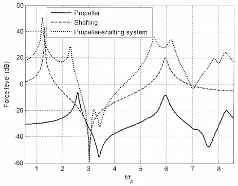
Fig.7 Force transmission functions of propeller,shafting and their coupling system
Based on the shafting model,when the propeller mass point is excited by a unit longitudinal harmonic force,the nodal force magnitude at a point close to the thrust bearing is com-puted,which represents the force transmission function of the shaft labeled as shafting in Fig. 7.The curve indicates that the shafting resonates at 2 frequencies,the nondimensional frequencies of which are 1.321 and 5.976,respectively.From shafting modal analysis,it is shown that there are 2 longitudinal vibration modes in the analysis frequency domain,the resonance frequencies of which exactly correspond to that of the shafting mentioned above.
Considering the effect of elasticity of the propeller and fluid loading,the propeller-shafting system dynamic model is used to calculate the force transmission function.This model is developed by replacing the propeller point mass in shafting model with the propeller 3D solid model and its surrounding fluid.
A longitudinal harmonic force with the amplitude of 1/6N is applied to each blade of the propeller,the nodal force at a location on shaft which is close to the thrust bearing is calculated.The result is labeled as propeller-shafting system in Fig.7.This plot indicates that 6 resonance frequencies exist in the anlaysis frequency domain,which are 1.214,2.284,5.521,6. 163,7.849 and 8.250.Through modal analysis,it is shown that 1.214 is corresponding to the first longitudinal resonance frequency of the shaft,which is 1.321 in the air.Due to the propeller-fluid coupling,this resonance frequency is reduced.
As for the propeller modes,2.284 is corresponding to the first longitudinal umbrella modal frequency of the propeller,which is 2.586 for the free propeller,and this resonance frequency is also reduced due to the change of boundary condition.The other four resonance frequencies are very complex to describe,they are the coupled modes for the propeller and the shafting.The second longitudinal mode along with the bending vibration mode of the shafting is all reflected in these four modes.The former two modes at 5.521 and 6.163 are also corresponding to the second longitudinal umbrella mode of the propeller while the latter two at 7.849 and 8.250 are corresponding to the third longitudinal umbrella mode of the propeller.
The longitudinal forces on propeller are transmitted to the hull via the shafting to excite the hull at the base of the thrust bearing,and induce the hull vibration and sound radiation.The vibro-acoustic characteristics of the hull have significant influence on the final radiated sound field.The radiated sound of the hull is calculated by the hull structure vibroacoustic numerical model.The sound transfer function of the hull is shown in Fig.8,which plots the sound source level when a longitudinal harmonic force with the amplitude of 1.0N is applied to the base of thrust bearing.Due to the special configuration of the SWATH,the hull has no apparent longitudinal vibration modes so that the sound radiation curve alters smoothly with respect to frequency.
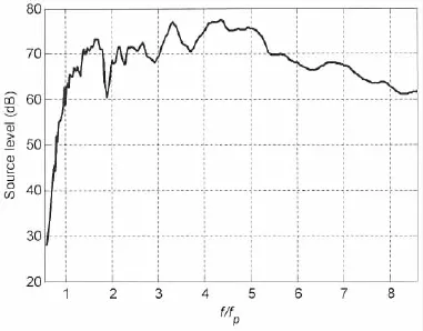
Fig.8 The sound transfer function of the hull structure
The coupled dynamic characteristics are studied based on the propeller-shaft-hull vibro-acoustic model.The force transmission function from blade to the thrust bearing is shown in Fig.9,in which one curve labeled as propeller-shafting system in Fig.7 is duplicated.The differences between these two curves indicate the impact of the hull structure.It can be concluded that due to the coupling between the propeller-shafting system and the hull structure, at the first resonance frequency of the propeller-shafting system,namely at 1.214,the magnitude of the force decreases by about 17 dB;at the two resonance frequencies of propeller’s second longitudinal harmonic mode,the magnitude decreases by about 5 dB;at other resonance frequencies the force magnitude keeps nearly the same.
The sound source level of the hull due to the propeller-shafting system excited by the propeller force is shown in Fig.10.In combination to Fig.9,it is concluded that the sound radiation characteristics of the propeller-shaft-hull coupling system due to the excitation of propeller force are determined by the sound radiation characteristics of the hull structure and the force transmission function of propeller-shafting system;in addition,the force transmission characteristics of propeller-shafting system also are affected by the dynamics of the hull structure.
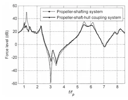
Fig.9 Force transmission function of propellershafting in coupling system
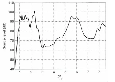
Fig.10 The sound transfer function of propellershaft-hull coupling system
4 Conclusions
An integrated vibro-acoustic numerical model for a SWATH ship which is comprised of propeller-shaft-hull structure coupling system is developed to investigate the longitudinal vibrational characteristics and its corresponding sound radiation.In this model,structural finite element method is employed for the hull,shaft and propeller,acoustic finite element methodis employed for their surrounding medium,fluid-structure coupling condition is enforced onto solid-fluid interface,and far-field condition is satisfied by the infinite element method.Through experiments,the experimental data and the numerical results are in good agreement,which demonstrates that our vibro-acoustic numerical model can meet the precision requirements for vibration and sound radiation analysis in low frequency domain.
The numerical calculation results show that the excitation from propellers transmitted to hull structure is magnified due to propeller-shaft-hull coupling,which occurs at the first and second longitudinal vibration resonance frequencies of shaft sub-system.Moreover,when the deformation of the propellers is taken into account,the similar dynamic magnification is found at certain resonance frequencies of the blades.The sound radiation characteristics of the SWATH due to the excitation of propeller force are determined by the sound radiation characterisitcs of the hull structure,and the force transmission function of propeller-shafting system.In addition,the force transmission characteristics of propeller-shafting system are also affected by the dyanmics of the hull structure.
[1]Zhu Xiqing,Tang Denghai,Sun Hongxing,et al.Study of low-frequency noise induced by marine propeller[J].Journal of Hydrodynamics,2000,15(1):74-81.
[2]Xie Jirong,Shen Shungen,Wu Yousheng.Calculational method for radiating sound excited by vibration of ship propeller [J].Journal of Ship Mechanics,2011,15(5):563-569.
[3]Xie Jirong,Shen Shungen,Wu Yousheng.Research status on noise radiation from vibrating hull induced by propeller and reduction measures[J].Shipbuilding of China,2010,51(4):234-241.
[4]Merz S,Kinns R,Kessissoglou N.Structual-acoustic sensitivity analysis of propulsion system parameters for a coup led FE/BE model of a submarine[J].The 16th International Congress on Sound and Vibration,2009:2341-2348.
[5]Xiong Ziying,Sun Hongxing,Zhu Xiqing.Prediction of low-frequency broadband noise induced by the interaction between injected turbulence and propeller[J].Shipbuilding of China,2014,55(3):1-11.
[6]Xie Jirong,Shen Shungen,Wu Yousheng.Transmission character of propeller excitation through shaft-line system to hull [J].Shipbuilding of China,2011,52(1):80-89.
[7]Neugebauer J,Abdel-Maksoud M,Braun M.Fluid-structure interaction of propellers[C]//IUTAM Symposium on Fluidstructure Interaction in Ocean Engineering.Springer Netherlands,2008,8:191-204.
[8]Qi Libo.Three-dimensional sono-elastical analysis method of propeller-shaft-hull coupled vibration and acoustic radiation of a ship[D].China Ship Research&Development Academy,2015.
摘要:文章研究了小水线面双体船的桨—轴—船体耦合系统在螺旋桨受宽带力激励下的纵向振动特性。建立了考虑周围流体介质作用的桨—轴—船体动态耦合系统的声振数值计算模型,经实船试验表明计算结果与试验结果吻合较好。采用该模型计算分析了桨—轴—船体耦合系统的振动特性。作用在螺旋桨上的激励力传递到船体时,受到轴系子系统的调制作用及推力轴承基座结构的刚度影响,在轴系一阶和二阶纵向振动模态处出现动力放大;考虑螺旋桨的弹性变形时,激励力在螺旋桨的桨叶若干纵向振动模态频率上也出现了明显的放大。在这些低频段的振动模态频率上,船体结构受放大的激励力作用,容易产生共振及声辐射。
小水线面双体船螺旋桨激励船体振动研究
熊晨熙,殷学文,段勇
(中国船舶科学研究中心船舶振动与噪声重点实验室,江苏无锡214082)
小水线面双体船;螺旋桨轴系船体耦合振动;声固耦合分析;声学无限元
O327
A
熊晨熙(1987-),男,中国船舶科学研究中心博士研究生,工程师;殷学文(1974-),男,博士,中国船舶科学研究中心高级工程师;段勇(1981-),男,博士,中国船舶科学研究中心高级工程师。
O327
A
10.3969/j.issn.1007-7294.2016.09.008
1007-7294(2016)09-1171-10
Received date:2016-05-09
Biography:XIONG Chen-xi(1987-),male,Ph.D.student,E-mail:XIONGCXCSSRC@163.com YIN Xue-wen(1974-),male,Ph.D.,senior engineer.
猜你喜欢
杂志排行
船舶力学的其它文章
- Recent Progress in Hydrodynam ic M odel Test for Two Floating Bodies at Close Proxim ity in W aves
- Numerical Analysis of Load-noise of a Highly-skewed Propeller behind Subm arine
- Comparison of Different Finite Element Modeling M ethods for the Soil-Pile Interaction of Jack-up Platform
- Structural Strength Evaluating M ethod of the Azimuth Thruster Propeller Blade
- Application of Inertia Relief in the Prediction of W elding Deformation for Large Complex Structures
- Dynam ic Pre-ultim ate Strength Evaluation of Containership based on a 2D M odified Hydroelasticity M ethod in Extrem e W aves
