Application of Inertia Relief in the Prediction of W elding Deformation for Large Complex Structures
2016-05-15WANGYangLUOYuCHENZhenXUEJian
WANG Yang,LUO Yu,CHEN Zhen,XUE Jian
(1.State Key Laboratory of Ocean Engineering,Shanghai Jiao Tong University,Shanghai 200240,China; 2.Jiangsu Newyangzi Shipbuilding Co.,Ltd,Wuxi 214532,China)
Application of Inertia Relief in the Prediction of W elding Deformation for Large Complex Structures
WANG Yang1,LUO Yu1,CHEN Zhen1,XUE Jian2
(1.State Key Laboratory of Ocean Engineering,Shanghai Jiao Tong University,Shanghai 200240,China; 2.Jiangsu Newyangzi Shipbuilding Co.,Ltd,Wuxi 214532,China)
Rigid-body motion boundary condition during computational welding mechanics,of which at least 6 degrees of freedom of welded structure will be fixed,is widely used to predict the welding distortion.However,because of the large scale and complexity of some structures,it is not advisable to consider the constraint for the unsupported welded structure during the computation.In this study, inertia relief method,the inertia force of the unconstrained structure is relieved to balance the external force,is proposed to investigate the welding deformation.Two methods are compared by predicting the welding deformation of a butt welded joint.Then,a hull block is taken as an example,simulations based on inherent deformation are conducted considering the inertia relief and rigid-body motion boundary conditions.By comparing the deformation of measured point,the computational results by using inertia relief are the most approximate to measurement results compared to other cases,and it is more convenient to set the boundary condition using the proposed method which provides an effective choice for the industrial application of welding structure deformation prediction.
inertia relief;rigid-body motion;inherent deformation;boundary condition; large complex structures;welding deformation
0 Introduction
As a high productive and practical joining method,welding is widely used in constructing and manufacturing industries such as shipbuilding,automobiles,passenger trains,bridges and pressure vessels industries[1].And the assembly process in these field essentially involves the joining of large structures.In order to predict the welding-induced distortions on large structures practically,many researchers have devoted much efforts to this topic up to now.
Generally,there are two main ways to predict the welding distortion of welded structures: thermal elastic-plastic finite element method and the elastic finite element method.The formerone can be effectively used to predict welding residual stress and distortion for small or medium welded structures,but this method is inapplicable to simulate the welding distortion for large welded structures for the considerable time consuming[2-5].The later one,using shell FE models with elements much larger than those required in thermal elastic plastic FE analysis can effectively predict the welding distortion of large structures[6-8].
In all above works,researchers mainly concern the optimum of computational methods and FE models.During the state of cooling down,an unconstrained welded structure is assumed to be under balanced external forces,and it can move as a rigid body.Before the finite element analysis,a series of constraints are required to eliminate the rigid body motion due to the singular stiffness matrix of the model.In order to precisely predict welding deformation especially for large welded structures,the effect of constraint should be taken into account.As large structures sometimes are complex,it is not advisable to consider the constraint for the unsupported welded structure during the computation,even though,in general,at least 6 degrees of freedom of welded structure will be fixed.Therefore,in this study an effective method of constraining the finite model is proposed to predict distortion during welding for large structures.
The technique of inertia relief,the inertia force of the unconstrained structure is relieved to balance the external force,has been a well-known approach for the analysis of unsupported systems including air vehicles in flight,automotives in motion,or satellites in space[9-11].In present method,inertia relief is introduced into the finite element analysis in order to replace the rigid-body motion boundary condition.In this study,in order to verify the practicality of inertia relief,rigid-body motion boundary condition and inertia relief are adopted to compare the welding deformation of a butt welded joint.Then,computation based on inherent deformation is conducted,and a hull block is investigated as an example.This method can be applied in elastic finite element analysis.
1 Theory of inertia relief
In the process of analyzing unconstrained structure by FEM,the stiffness matrix[K] is singular and therefore the flexibility matrix[G]=[K]-1does not exist.The motion as a rigid body will be eliminated and a new set of applied loads(relative forces)will be used to analyze the elastic behavior of the unconstrained system[12].
1.1 Relative motion
For a unconstrained moving dynamic system,the total displacement vector{x} may be expressed in a pure rigid motion displacement vector {xr}and a relative elastic displacement vector{xe},and considering{x}=[Φ]{η},thus:

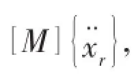
The undamped equation of motion of a dynamic system loaded with the dynamic force{F}is:

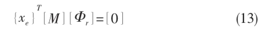
With the introduction of Eq.(1)into Eq.(2)and knowing that[K][Φr]=[0],we obtain:

1.2 Relative forces
The uncoupled equations of motion of the dynamic system,exposed to the force vectorand expressed in the generalized coordinates{η}can be written as
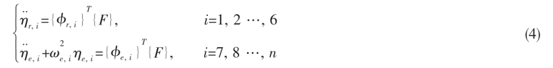

As shown in Fig.1,the relative elastic forcesare defined as
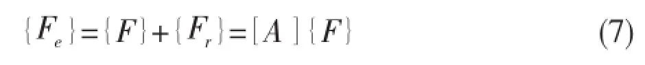
with
1.3 Flexibility matrix
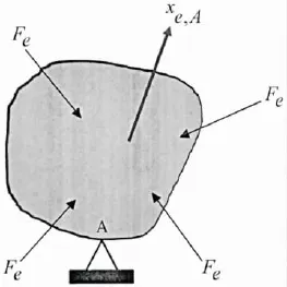
Fig.1 Constrained structure loaded with relative forces
We want to calculate the elastic displacement{xe,A}of the constrained structure,due to the relative elastic force{Fe},with respect to point A.The displacementis

The displacement and rotations of point A are zero

The real relative elastic deformationis a summation of the relative elastic deformation and fractions of rigid body motion.Thus the relative elastic deformationis
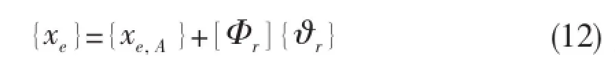
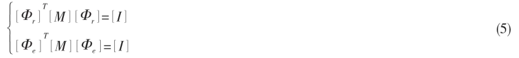
We will remove the fraction of rigid body motion and force the displacement vectorto be mass orthogonal with the rigid body modes[Φr],thus
This means that the vector of generalized coordinatesis equal to
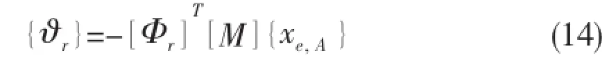
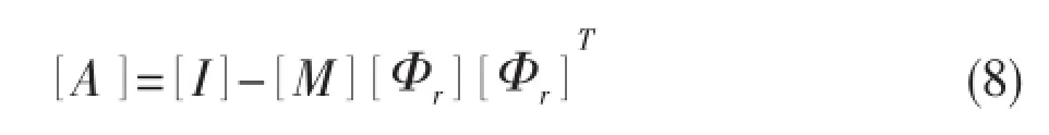
The relative elastic deformationfinally becomes
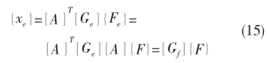
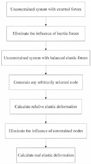
Fig.2 Calculation procedure of inertia relief
The calculation procedure is shown in Fig.2.
2 Com parison of two methods
As a simple example,a butt welded joint is examined to predict welding deformation based on inherent strain theory using rigid-body motion and inertia relief.A serial computations employing ABAQUS based on inherent strain theory,in which the same magnitude of inherent deformations and different boundary conditions are used,is carried out to show the difference between two kinds of boundary conditions.
2.1 Finite element model of butt welded joint
A rectangular plate with a length of 2 000 mm,a width of 1 000 mm,and a thickness of 18.5 mm is selected as a test specimen.The welding deformation behavior of butt welded joint is computed using FE elastic analysis based on ABAQUS code.The finite model is shown in Fig.3.The size of element is 20 mm×40 mm.The number of nodes is 2 601,and that of elements is 2 500.The element type is S4R.According to the theory of inherent deformation[13],the distributions of inherent strain remain in a narrow area near the welding line as shown in Fig.3.
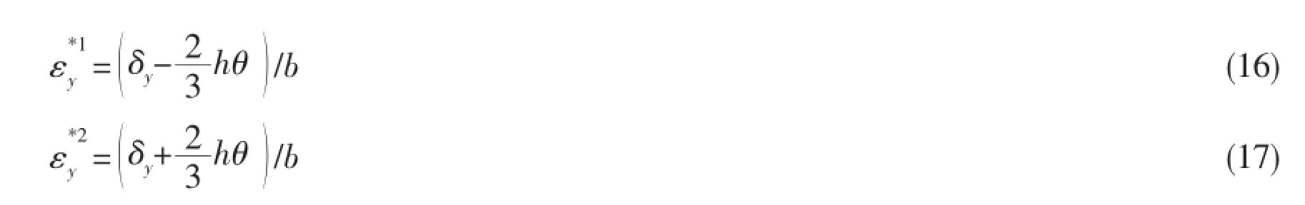
In order to calculate the welding deformation caused by inherent strain,the thermal expansion coefficient of the element in inherent strain zone is set to be different from basic plate zone.Fig.4 shows the transverse section of the region where the equivalent inherent strain distributes. The width of the area where the equivalent inherent strain distributes is b.The strain components to be considered are in the transverse and the longitudinal directions.The component of the equivalent inherent strain in the transverse direction εy*forms the transverse shrinkage and the angular distortion.These components are assumed to distribute in two layers with the same thickness.The equivalent inherent strains distribute uniformly in each layer but the valuesandare different.According to the definition of the equivalent inherent strain,these are given by the following equations:
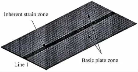
Fig.3 Shell element model of butt welded joint
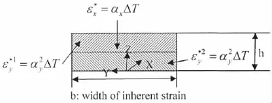
Fig.4 Distribution of inherent strain
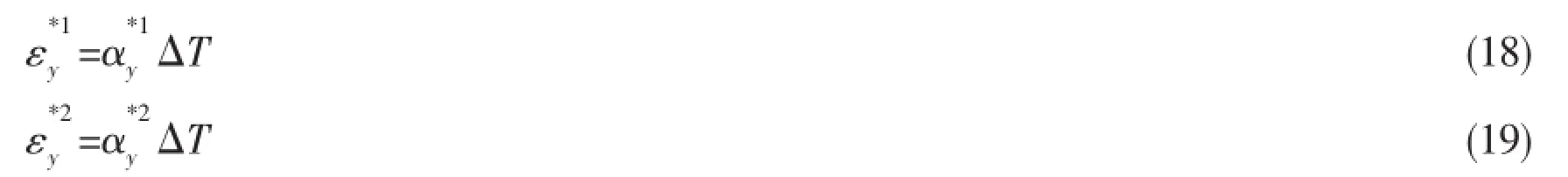
In the computation using ABAQUS,these inherent strains are given as the thermal strain under the temperature change of ΔT i.e.,

The values of thermal expansion coefficient used in this model is listed in Tab.1.Then, Elastic FE analysis is carried out by changing the thermal boundary conditions of the model.
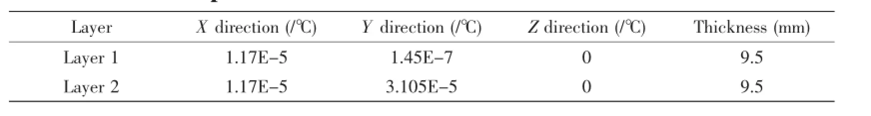
Tab.1 Expansion coefficient values in inherent strain zone
2.2 Comparison between different computation results
Firstly,the rigid-body motion,in which 6 degrees of freedom are fixed,is employed as boundary condition for a normal case.Fig.5(a)shows the computational deformation in Z direction of the joint.The undeformed shape is shown as black lines in Fig.5(a).Then,an elastic analysis using inertia relief and same magnitude of expansion coefficient values is carried out to predict welding deformation.Computational result is shown in Fig.5(b),where the good agreement of two contours between the computational results with different boundary condition shown in Fig.5(a)and(b)can be observed.For the quantitative comparison between two cases,the deflection along line 1 defined in Fig.3 between two cases are plotted in Fig.6.As wecan see from this figure,the distribution of deflection in two cases are the same.The deformed model using rigid-body motion can be changed into the one using inertia relief by translating coordinate axis(0.031 mm in positive direction of X coordinate,0.117 3 mm in positive direction of Y coordinate and 0.785 3 mm in positive direction of Z coordinate).
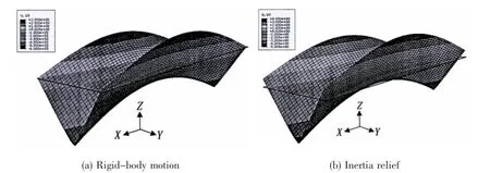
Fig.5 Computational welding deformation by elastic analysis with different boundary conditions
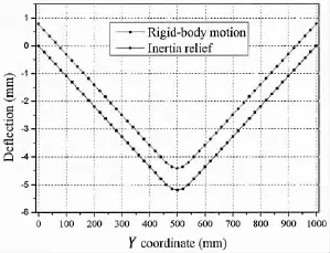
Fig.6 Deflection along line 1
3 App lication
Based on the result of predicting the welding deformation in the beam by using inertia relief,the reliability of using inertia relief to simulate the welding deformation of large structure is discussed in this chapter.In the first section,a series of computations of the welding deformation of typical hull structure employing Weld-Sta(developed by Structure Mechanics Research Institute of Shanghai jiaotong University and Joining and Welding Research Institute of Osaka University)based on elastic analysis,in which the same magnitude of inherent deformations and different boundary conditions(three kinds of rigid-body motion boundary condition(fixed in X plane,Y plane and Z plane,respectively)and inertia relief method)are used,is carried out.Then the in-plane(in X direction and Y direction)and out-of-plane(in Z direction)welding deformations of four cases are compared.Results show that the welding deformation in X direction is similar,while the one in Y direction and Z direction is different. By comparing the out-of-plane deformation of measured point,the computed results by using inertia relief are mostly approximate to measurement results compared to other cases.
3.1 FEM model
The hull block which is taken as an example is a part of the second cargo hold in 4 250 TEU container ship.The finite model of this hull block is meshed in the commercial software(Hypermesh)and imported into Weld-Sta as shown in Fig.7.The length,width and height of this block are 8 200 mm,27 622 mm and 4 600 mm,respectively.The computational model is made with 2D shell element including three nodes and four nodes,and the number of node and element are 6 082 and 5 254,respectively.The X direction,the Y direction and the Z direction are along the ship length,the ship width and the ship depth,respectively.Thename of each part and its thickness of the hull block are shown in Tab.2.
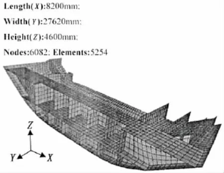
Fig.7 FE model of a typical hull block
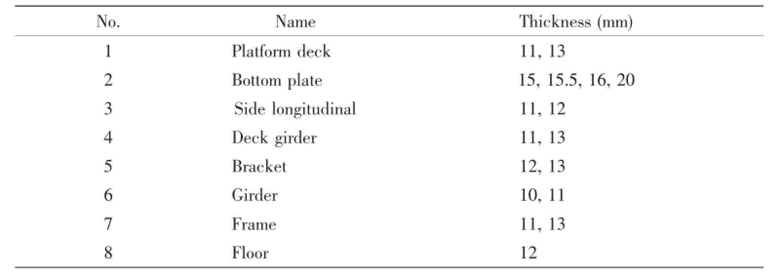
Tab.2 Shell element attributes of the model
3.2 Welding lines of FEM model
In this model,all members are tack welded,and 168 fillet joints are added on the finite model as shown in Fig.8.The material is made of shipbuilding steels A32.Tab.3 gives the chemical composition and mechanical properties of A32.Welding method is CO2gas metal arc welding,and the filler metal is flux cored wire.By importing the welding parameters of each welded joint including the basic material,the welding method,the number of welding passes,the size of joint(the thickness of web and flange)and groove and welding conditions(current,voltage,velocity and efficiency),the inherent deformation(longitudinal inherent shrinkage,transverse inherent shrinkage and angular distortion)of each fillet joint can be calculated by inherent deformation database of Weld-sta.
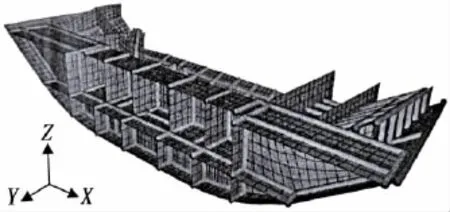
Fig.8 Weldlines of the typical ship block
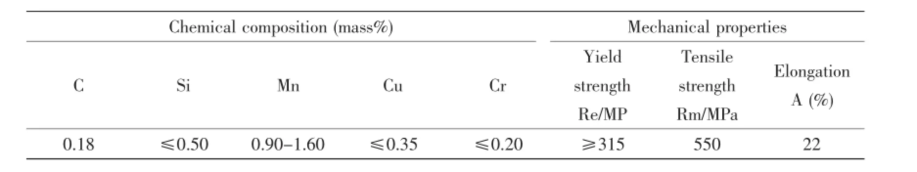
Tab.3 Chem ical com positions and mechanical properties of shipbuilding steel A32
3.3 Results and discussion
In order to compare the influence of different boundary conditions on the prediction of welding deformation in the large structure,three kinds of rigid-body motion boundary conditions are proposed in this study.Six nodes(A(0,12 186,4 574),B(8 049,13 829,4 574),C (8 049,-13 829,4 574),D(8 200,0,0),E(7 100,0,4 304),F(900,0,2 370))are selected as fixed points in the elastic FE analysis.The detailed boundary condition of each case is shown in Tab.4.In this study,inertia relief method is used in case 4,where no rigid-body motion is applied in this case.
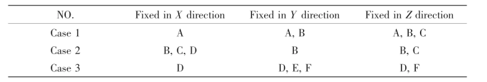
Tab.4 Rigid-body motion boundary conditions of different cases
Fig.9 shows the welding deformation of case 1.As it can be seen from Fig.9(a),the shrinkage in Z direction of the structure is concentrated in the bottom plate due to three nodes(node A,node B and node C)of this part are constrained in the direction of ship depth.Fig.9(b)shows the top view of the deformed model after welding.One can see that the shrinkage in Y direction is concentrated in the one side of the structure.The reason is that the constraint in Y direction(node A and node B)is focus on the other side of the block.Also, the whole structure can deform freely in X direction because only one node (node A)is fixed in this direction.
The welding deformation of case 2 is shown in Fig.10.Fig.10(a)shows the isometric view of the deformed model after welding.From this figure, it can been seen that the shrinkage in Z direction is concentrated in the bottom plate due to the constraint in the direction of ship depth of two nodes (node B and node C).Furthermore,because three nodes(node B,node C and node D)are constrained on the side near the stern in the direction of ship length,the shrinkage in X direction of the structure shown in Fig.10(b)is concentrated in the other side of the structure.Finally,the whole structure can deform freely in Y direction because only one node(node B)is fixedin this direction.
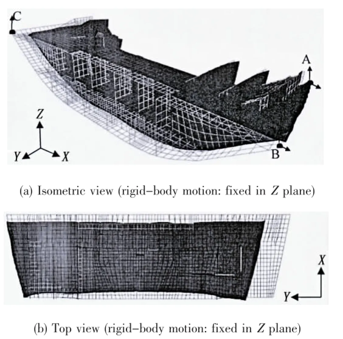
Fig.9 Welding deformation of case 1
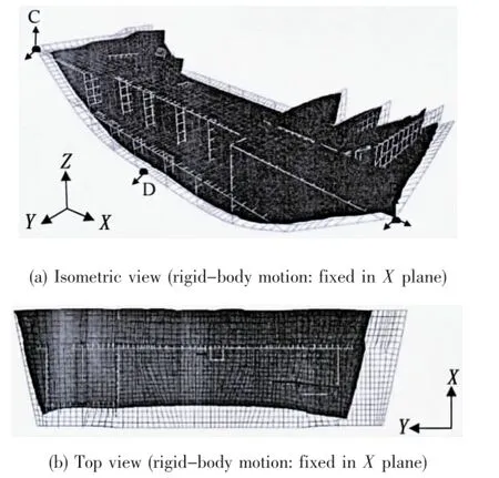
Fig.10 Welding deformation of case 2
Fig.11 shows the welding deformation of case 3.In this case,the shrinkage in Z direction is found in both platform deck and bottom plate due to the constraint of two nodes(node D and node F)in this direction as shown in Fig.11(a).Fig.11(b)shows the top view of the deformed model after welding.The shrinkage in Y direction of the structure can be found in both sides of the bottom plate because three nodes(node D,node E and node F)is constrained in the middle part of the block.The whole structure can deform freely in X direction because only one node(node D)is fixed in this direction.
Fig.12 shows the welding deformation of case 4.As it can be seen from this figure,the whole structure shrinks towards the center of the mass. And this phenomenon is ordinary in production of hull block.Moreover,the constraining anti-forces of constraint nodes are large by using rigid-body motion boundary condition.Unreasonable rigid-body boundary condition in FE analysis will lead to false results. Therefore,it is important to design reasonable boundary condition for computation.
Fig.13 compares the welding deformation in X direction among four cases.From this figure,one can observe that the welding deformations in X direction of four cases are similar in spite of the welding deformation of case 2 is slightly different from other cases in the one end and the middle part of block.
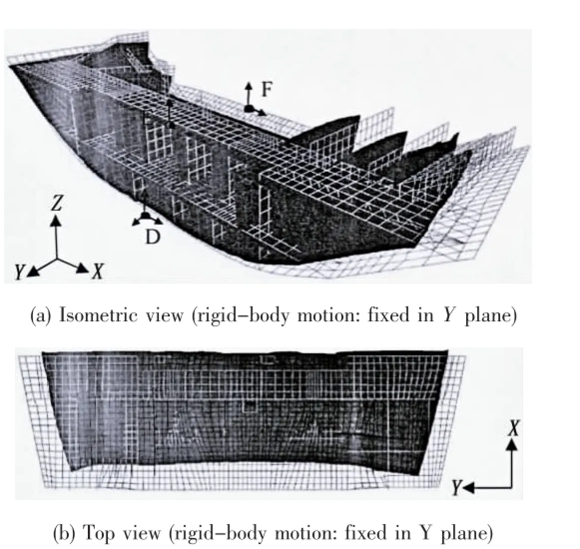
Fig.11 Welding deformation of case 3
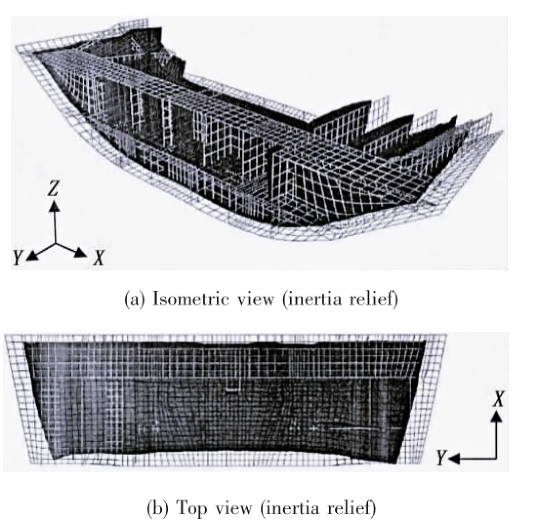
Fig.12 Welding deformation of case 4
Fig.14 shows the welding deformation in Y direction of the above four cases.It is clear that the difference among four cases is obvious near the position where X equals to 0 mm, while the difference becomes smaller when the value of X coordinate is larger than 2 000 mm. Furthermore,the welding deformation of case 1 is different compared to other cases in the po-sition where X approximately equals to 8 049 mm.This implies that the boundary condition of case 3 has a similar effect with that of case 4 in Y direction.And the constraint of node B in Y direction will cause different welding deformation in this direction compared to cases without constraining this node.Comparing the symmetry of the structure in X direction of that in Y direction,this block is more asymmetric in X direction.And different boundary condition may have great influence on the deformation of this structure.
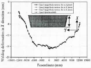
Fig.13 Welding deformation in X direction
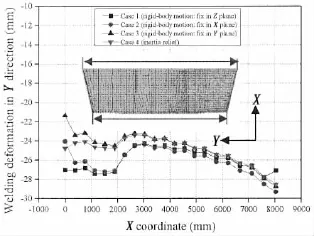
Fig.14 Welding deformation in Y direction
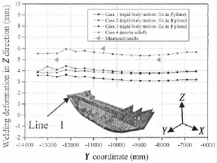
Fig.15 Welding deformation in Z direction along line 1
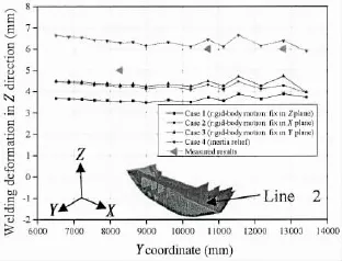
Fig.16 Welding deformation in Z direction along line 2
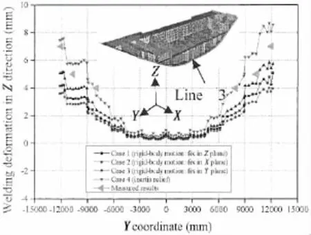
Fig.17 Welding deformation in Z direction along line 3
Figs.15 and 16 show the welding deformation in Z direction along line 1 and line 2,respectively.From these two figures,it can be seen that the welding deformation in Z direction of case 4 is the largest,and that of case 2 and case 3 is similar.In this figure,the measured results along line 1 are also plotted.It is clear that the welding deformation along line 1 predicted by case 4 is the closest to the experimental value among four cases.Fig.17 shows the welding deformation in Z direction along line 3.The simulated results of fourcases are similar in the middle part of the block within the range-4 420 mm
4 Conclusions
A practical computational approach applying boundary condition(inertia relief method)to predict welding deformation was proposed.The following conclusions can be drawn:
(1)It is more convenient to apply boundary condition for predicting welding deformation of large structure by using inertia relief method than body-rigid motion method;
(2)There is no difference between the deformed model calculated by two methods based on inherent strain theory for simple structures;
(3)Complicated rigid-body motion boundary conditions are required in predicting the welding deformation of large complicated structures.The good agreement between computed results using inertia relief and measured ones shows that the computation using inertia relief can obtain reliable results in predicting the welding deformation of large complicated structure.
Acknow ledgements
This research is technically supported by Jiangsu Newyangzi Co.,Ltd and is financially supported by Science and Technology Department of Jiangsu Province(Grant No.BE2010172).
[1]Satoh K,Ueda Y,and Fujimoto J.Welding distortion and residual stresses[M].Sampo Publications,Tokyo,1979.
[2]Wang J,Ueda Y,Murakawa H,et al.Improvement in numerical accuracy and stability of 3-D FEM analysis in welding [J].Welding Journal,1996,75(4):129-134.
[3]Deng D,Luo Y,Serizawa H,et al.Numerical simulation of residual stress and deformation considering phase transformation effect[J].Trans.JWRI,2003,23:325-333.
[4]Deng D,Murakawa H.Numerical simulation of temperature field and residual stress in multi-pass welds in stainless steel pipe and comparison with experimental measurements[J].Computational Material Science,2006,37:269-277.
[5]Teng T L,Fung C P,et al.Analysis of residual stresses and distortions in T-Joint fillet welds[J].Pressure Vessel and Piping,2001,78(8):523-538.
[6]Brown S B,Song H.Implications of three-dimensional numerical simulations of welding of large structures[J].Welding Journal,1992,71(2):55-62.
[7]Wang J H,Luo H.Prediction of welding deformation by FEM based on inherent strains[J].Journal of Shanghai Jiaotong University(English Editorial Board),2000,5(2):83-87.
[8]Luo Y,Deng D,Xie L,Murakawa H.Prediction of deformation for large welded structures based on inherent strain[J]. Transactions of JWRI,2004,33:65-70.
[9]Bisplinghoff R L,Ashley H,Halfman R L.Aeroelasticity[M].Addison-Wesley Publishing Company,Inc.Boston,1955.
[10]Nelson M F,Wolf J A.Use of inertia relief to estimate impact loads[C].Proceedings of International Conference on Vehicle.Structural Mechanics,1977:149-155.
[11]Harry G S.MSC/NASTRAN Primer static and normal modes analysis[M].Shaeffer Analysis,Inc,1979.
[12]Wijker J J.Mechanical vibrations in spacecraft design[M].Springer,2004:303-312.
[13]Luo Y,Ishiyama M,Murakawa H.Welding deformation of plates with longitudinal curvature[J].JWRI Transaction,1999, 28:57-65.
惯性释放法在大型复杂结构焊接变形预测中的应用
王阳1,罗宇1,陈震1,薛健2
(1.上海交通大学海洋工程国家重点实验室,上海200240;2.江苏新扬子造船有限公司,江苏无锡214532)
在进行大型结构焊接变形有限元分析时,为了固定整体结构刚体位移必须施加不少于6个自由度的约束,但对于自由状态下的结构而言,如何施加这6个最少约束是非常的困难,长期以来是困扰研究人员的难题,也是焊接结构有限元分析在工业现场应用的一个瓶颈。所谓惯性释放法就是可以在不加约束的情况下模拟自由结构的变形。该文将在航海航空领域得到广泛应用的惯性释放法引入大型焊接结构变形分析,解决了自由状态下结构必须施加约束的问题。首先以典型的对接接头为例,比较了两种不同的约束方法之间的差别。然后通过一个典型的船体焊接变形预测的实例,验证了惯性释放法在大型结构中应用的可行性,为焊接结构变形分析在工业生产中广泛应用提供了一个有效的方法。
惯性释放;刚体位移;固有变形;边界条件;大型复杂结构;焊接变形
TG404
A
王阳(1986-),男,上海交通大学博士研究生,通讯作者;罗宇(1971-),男,博士,上海交通大学教授;陈震(1976-),男,博士,上海交通大学副教授;薛健(1967-),男,高级工程师。
TG404
A
10.3969/j.issn.1007-7294.2016.09.006
1007-7294(2016)09-1147-13
Received date:2016-05-22
Foundation item:Supported by Science and Technology Department of Jiangsu Province(Grant No.E2010172)
Biography:WANG Yang(1986-),male,Ph.D.student of Shanghai Jiao Tong University,E-mail:maible@sjtu.edu.cn; LUO Yu(1961-),male,Ph.D.,professor; CHEN Zhen(1976-),male,Ph.D.,associate professor of Shanghai Jiao Tong University; XUE Jian(1967-),male,senior engineer.
猜你喜欢
杂志排行
船舶力学的其它文章
- Research on Influence of Rudder-Bulb-Fin Parameters on Hydrodynam ic Performance of Tw isted Rudder
- Numerical Study on Hydrodynam ics of Ships in Oblique M otion with M ulti-Degree of Freedom
- Study on Vortex-induced M otion Characteristics of Variable Cross Section M ulti-column of a New Type of Deep Draft FDPSO
- Slamm ing Study of W edge and Bow-flared Sections
- Dynam ic Pre-ultim ate Strength Evaluation of Containership based on a 2D M odified Hydroelasticity M ethod in Extrem e W aves
- Structural Strength Evaluating M ethod of the Azimuth Thruster Propeller Blade