Preliminary electromagnetic analysis of the COOL blanket for CFETR
2024-03-18ShuailingLU鲁帅领XuebinMA马学斌andSonglinLIU刘松林
Shuailing LU (鲁帅领) ,Xuebin MA (马学斌) and Songlin LIU (刘松林)
1 School of Nuclear Science and Technology,University of Science and Technology of China,Hefei 230026,People’s Republic of China
2 Institute of Plasma Physics,Hefei Institutes of Physical Science,Chinese Academy of Sciences,Hefei 230031,People’s Republic of China
Abstract The supercritical CO2 cOoled Lithium-Lead (COOL) blanket has been designed as one advanced blanket candidate for the Chinese Fusion Engineering Test Reactor (CFETR).This work focuses on the electromagnetic (EM) loads (Maxwell force and Lorentz force) acting on the COOL blanket,which are important mechanical loads in further structural analysis of the COOL blanket.A 3D electromagnetic analysis is performed using the ANSYS finite element method to obtain EM loads on the COOL blanket in this study.At first,the magnetic scalar potential (MSP) method is used to obtain the magnetic field and the Maxwell force on the COOL blanket.Then,the magnetic vector potential (MVP) method is performed during a plasma disruption event to get the eddy current distribution.At last,a multi-step method is adopted for the calculation of the Lorentz force and the torque.The maximum Lorentz forces of inboard and outboard blanket structural components are 5624 kN and 2360 kN respectively.
Keywords: CFETR,COOL blanket,finite element analysis,electromagnetic analysis
1.Introduction
The Institute of Plasma Physics,Chinese Academy of Sciences (ASIPP) has developed the supercritical CO2cOoled lithium-lead blanket (COOL) concept [1] as one candidate blanket for the Chinese Fusion Engineering Test Reactor (CFETR).The COOL blanket would bear large electromagnetic (EM) loads especially during plasma disruption events,which is one of the most technical challenges [2,3].The electromagnetic loads include the Maxwell force and the transient Lorentz force under plasma disruption events.The ferromagnetic material (RAFM steel) is magnetized in the high magnetic field generated by the coils and the plasma current in the CFETR,and it interacts with the magnetic field to produce the Maxwell force on the COOL blanket.Under plasma disruption events,the current of plasma decays rapidly in a short period of time resulting in the change of magnetic flux through the COOL blanket,so large eddy currents are generated in the COOL blanket.Finally,the eddy current interacts with the magnetic field to produce large Lorentz forces on the blanket [3,4].
This work starts with the calculation of the Maxwell force on the COOL blanket during normal functioning.The Maxwell force is calculated according to the virtual work method,which is one of the methods in ANSYS software,and the method used in the static magnetic analysis is the finite element magnetic scalar potential (FE MSP) method.Besides that,the magnetic field can also be obtained for the calculation of Lorentz force.Then the finite element magnetic vector potential (FE MVP) method is used for transient magnetic analysis in the COOL blanket during plasma disruption events,such as major disruption,and the result of eddy current is obtained for the calculation of Lorentz force.Finally,the Lorentz force is calculated by the vector-product of the eddy current and the magnetic field,and the torque is calculated by the vector-product of the force arm and the Lorentz force [3,4].
2.COOL blanket
In the CFETR machine configuration,there are 16 blanket sectors,and two inboard segments and three outboard segments are contained in one sector.Figure 1 shows the structure of the COOL blanket.The 3# blanket unit is shown as an example in the bottom right of figure 1.The U-shape First Walls (FWs),caps and Manifolds (MFs) form an enclosed structure in each blanket segment.The tungsten armor is on the surface of the FWs to receive the high heat flow.In the enclosed structure,the stiffening plates (SPs)and cooling plates (CPs) divide the BZ into twelve circuits for the PbLi outboard,as shown in the bottom right of figure 1.The FCIs are used for PbLi made of SiC.A gap of 5 mm exists between the structural components and the FCIs,and it is filled with PbLi [1].The Reduced Activation Ferritic/Martensitic (RAFM) steel is the candidate structural material in the COOL blanket,because of its excellent radiation resistance,low activation,and thermodynamic stability.
3.Static magnetic analysis
3.1.Finite element model
In order to simplify the calculation,one blanket sector of the full 16 sectors has been constructed because of the symmetry of the full model along the toroidal direction in static magnetic analysis.Figure 2 shows the FE model (FEM)included 3 outboard blanket segments,2 inboard blanket segments,coils,void,and far-field.To mesh conveniently and calculate efficiently,the RAFM steel is filled in the cooling channels of blanket segments.Due to the model simplification,the B-H curve of the RAFM steel is corrected.However,the complete model of the coils and plasma (360°) is modeled as current-carrying according to the requirement of the ANSYS software.The coils in the static magnetic analysis include 16 Toroidal Field (TF) coils,8 Center Solenoid (CS) coils,7 Poloidal Field (PF) coils,and the plasma.The element types used in the static analysis are SOLID 96,SOURC 36 and INFIN 111,as listed in table 1.
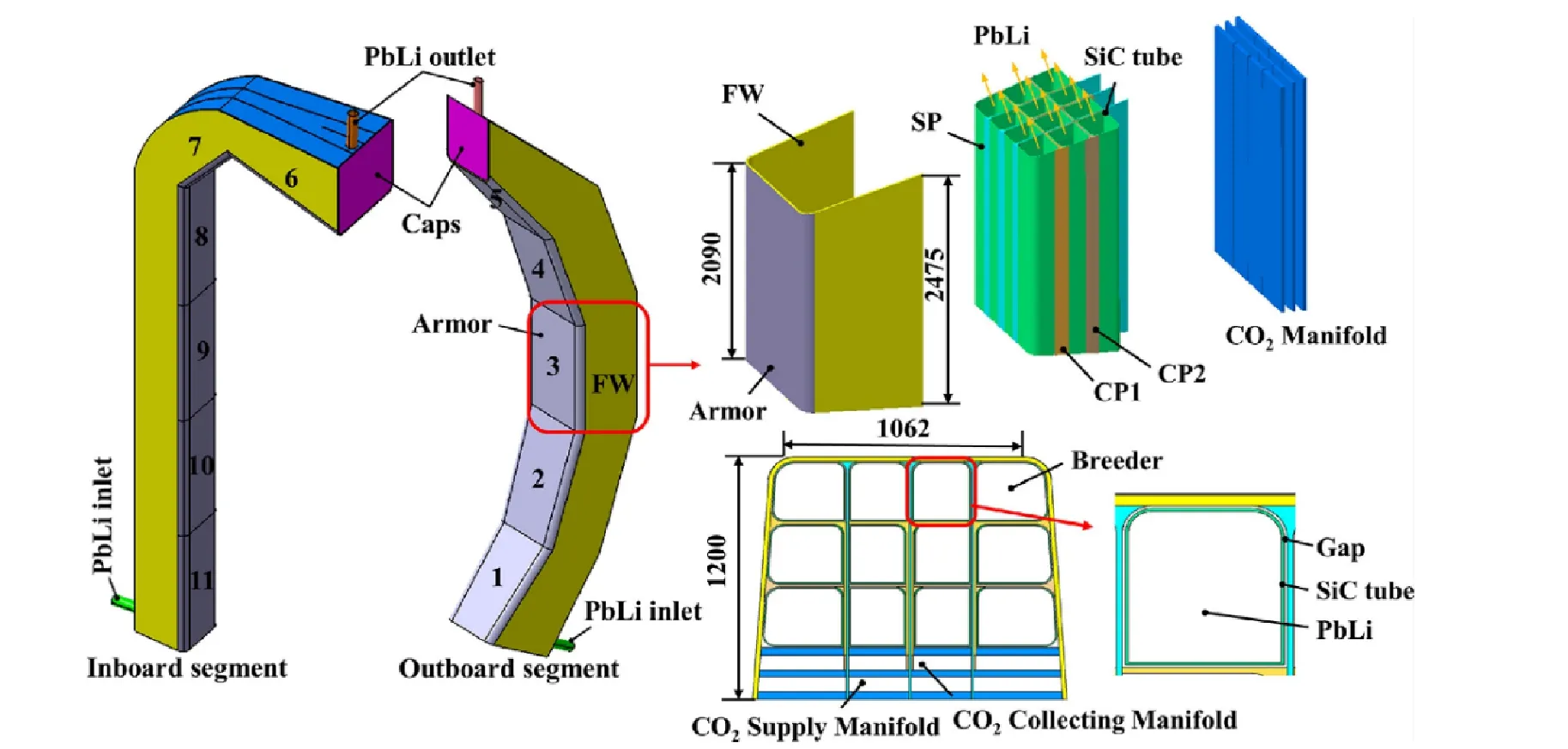
Figure 1.The overall structure of the COOL blanket.
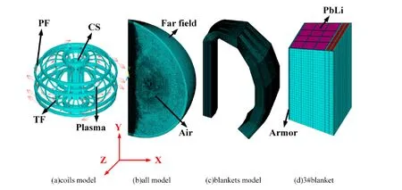
Figure 2.FEM of COOL blanket for static analysis.
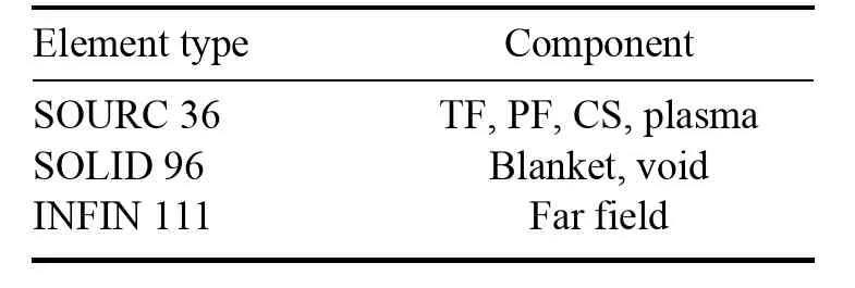
Table 1.Element type for static analysis.
3.2.Material
The relative permeability of void,PbLi and SCI in FEM is 1 in this paper.The RAFM is the only ferromagnetic material.The magnetization curve (B-H curve) shown in figure 3 describes the relationship between the magnetic flux density and the magnetic field intensity of the RAFM steel.The B-H curve is corrected according to the following formula [5,6]:
the Beffis the corrected B of the RAFM steel;µ0is the vacuum magnetic permeability;H is the magnetic field intensity;M is the magnetization intensity;Veffis the steel volume in the simulation model;Vmodis the steel volume in the original model of blankets.
3.3.Loads
The loads in the static analysis are the current in PF coils,TF coils,CS coils and the plasma.The SOURC 36 element is used to model the current-carrying components to carry out these current loads.The current of all coils and the plasma [7]is shown in table 2.
3.4.Boundary conditions
Three boundary conditions are applied in static analysis.It is essential to mesh concordantly on both sides of the 22.5°sector so that the cyclic boundary condition can be applied in the model.Then,the flux-parallel boundary condition is considered in this model to ensure that the magnetic orientation is parallel to the central axis.The last one is the infinite field boundary condition by using the INFIN 111 element for the far field and adding infinite surface flags.

Table 2.Current of coils and plasma.
3.5.Result
Figure 4 shows a poloidal-radial section view of the magnetic flux density in the CFETR.The maximum magnetic flux density is 19.86 T and appears in the vicinity of the central coil.This is the result of the magnetic field of all CS coils being superimposed on the poloidal axis.According to the TF design requirement,the magnetic flux density at the plasma radius of 7.2 m is 6.5 T,the result is in accordance with the TF coils design parameter [7].
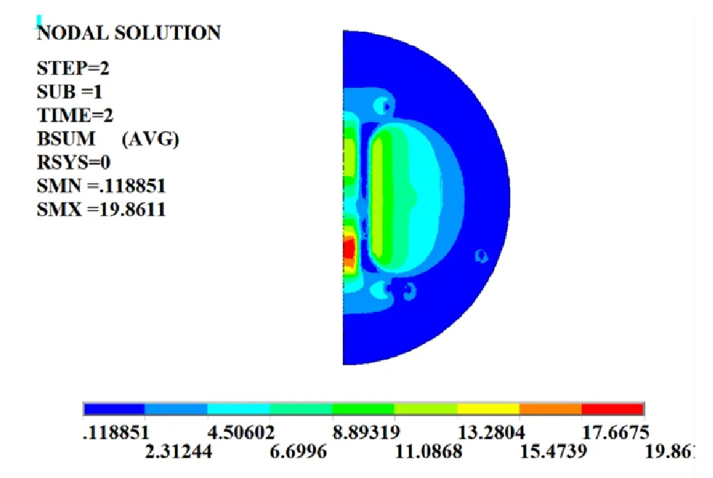
Figure 4.Poloidal-radial section view of the magnetic flux density.
The distribution of the magnetic flux density decreases along the radial direction inside the TF coils,so the magnetic flux density in inboard blanket segments is generally greater than that in outboard blanket segments.The magnetic flux density in blanket structural components is larger than that in the other components (such as PbLi) at the same radial position,due to that the RAFM steel produces an additional magnetic field in high magnetic fields.The Maxwell forces on the inboard blanket segments and the outboard blanket segments are obtained by the virtual work method.The Maxwell force on blankets is listed as table 3.The coordinate system used in this paper is the Y-axis cylindrical coordinate system shown in figure 2.The negative sign of force indicates that the force direction is in the opposite direction of the coordinate axis.The Maxwell force acting along the radial direction is greater than those along the other two directions in both the inboard and the outboard blanket segments,and the Maxwell force on the inboard blanket is also larger than that on the outboard blanket due to the higher magnetic flux density.The force along the poloidal(Fy) in the inboard segment is smaller than that in the outboard segment by an order.The inboard blanket segment consists of one straight section and one curved section.Because of the symmetry of the straight section,the force on this section would be offset,and the arrangement of the outboard blanket segment is completely asymmetrical in the pole direction.The maximum Maxwell force on the inboard blanket is 8434 kN,while the maximum Maxwell force on the outboard blanket is 3447 kN.
4.Transient magnetic analysis
CFETR plasma may be disrupted under accident conditions and the plasma current can be reduced to zero in short periods of time (tens of milliseconds).The sharp change of the plasma current results in high eddy current in blanket segments.The interaction between the eddy current and the magnetic field generates strong Lorentz force and torque on the blanket,which is likely to cause the failure of the blanket components [6,8].Because accurate plasma disruption events have not yet been developed in the CFETR,the transient magnetic analysis is performed under one assumed 36 ms linear plasma disruption event [6,9].The plasma current is represented by formula (2).I0is the initial current,which is 14 MA.τ is the attenuation coefficient,which is 36 ms.t is the time and I is the plasma current at time t
4.1.Multiple-step method for Lorentz force and torque
The FE MVP method is used in the transient magnetic analysis for Lorentz force calculation.However,when the structural material of the COOL blanket (RAFM) is included in the FE model,the calculation is extremely slow and inaccurate.Another calculation method of the Lorentz force named the ‘multiple-step method’ [3,10] is used by combining the FE MSP and FE MVP methods to get more accurate results.Firstly,in the transient magnetic analysis,the eddy current of the blanket during the MD event is obtained using the MVP method.Secondly,the magnetic field of the blanket duringthe MD event is assumed to be the same as the magnetic field in the static magnetic analysis.Because the magnetic field in the blanket is mainly generated by the TF coils,the magnetic field in the blankets generated by the plasma is small and can be ignored.Finally,the Lorentz force is calculated by the vector cross product of the eddy current obtained using the MVP method in the transient magnetic analysis and the magnetic field obtained using the MSP method in the static magnetic analysis.The Lorentz force and torque are calculated according to formula (3) and formula (4),respectively,and the flow chart of the ‘multiplestep’ is shown in figure 5.

Table 3.Maxwell force on COOL blankets.
The F(t) and M(t) are the total Lorentz force and the total moment on blanket,respectively;i is the number of element,N is the total number of elements,F(t)iis the Lorentz force of element i,J(t)iis the eddy current density of element i,Biis the magnetic field of element i,Viis the volume of element i,Liis the arm of force of element i.
4.2.Finite element model
A blanket sector (22.5°) of the 16 blanket sectors has been constructed to simplify calculations too.As shown in figure 6,The FEM includes 3 outboard blanket segments,2 inboard blanket segments,vacuum vessel (VV),void,tungsten armor,far field and plasma.The magnetic field in the blankets is replaced by the magnetic field in the static analysis due to the coils remaining in operation after the MD events,so that the coils are not built [11].The plasma model is built to carry current loads of MD events.The tungsten armor could generate great eddy current in MD events due to its small resistivity,so it is included in the model.Other components of blankets are also modeled in detail to ensure accurate results.For the transient analysis element type,the SOLID 97 and INFIN 111 elements are used in the MVP method,and it is distinguishing between conductive and insulating materials by using different degrees of freedom of element type.
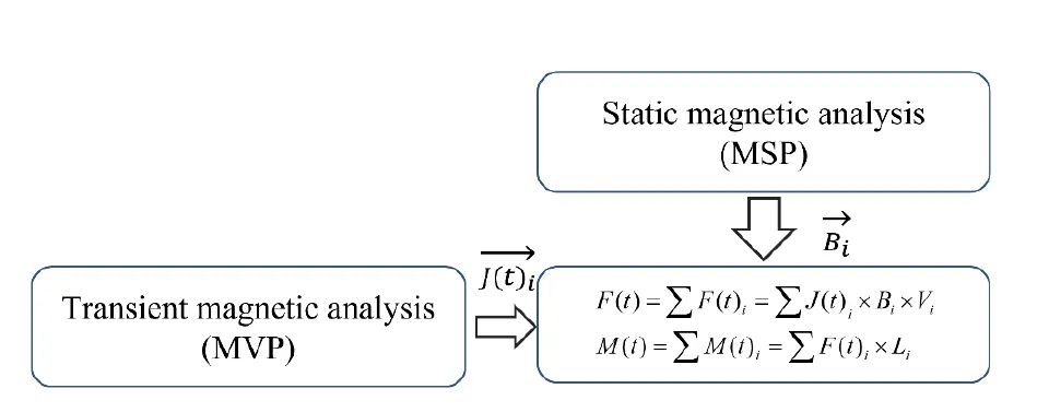
Figure 5.Flow chart of the ‘multiple-step’.
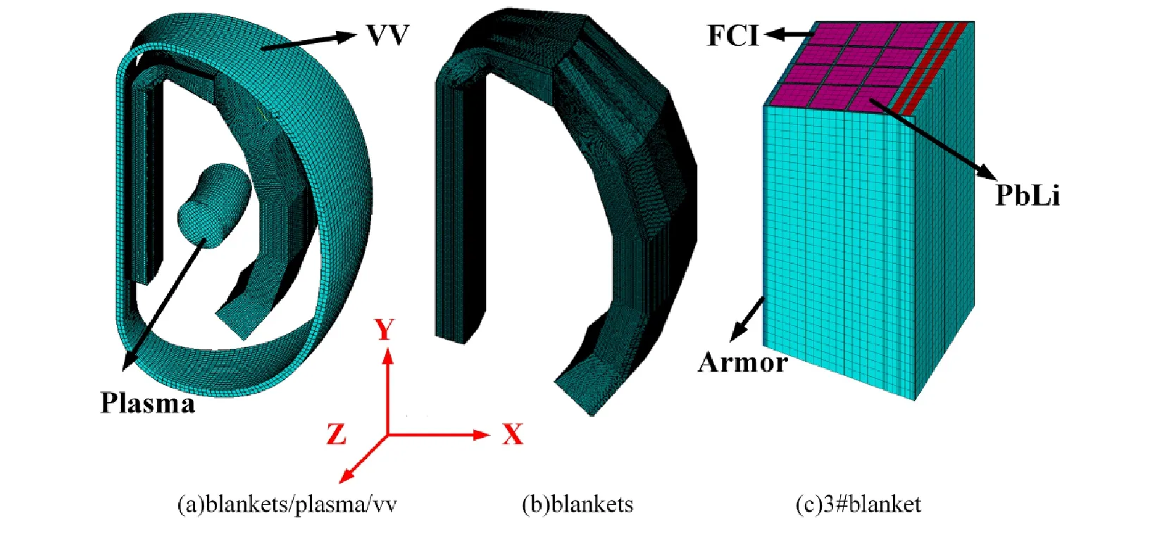
Figure 6.FE model for transient analysis.
The influence of FCI on the eddy current distribution and the Lorentz force distribution of the COOL blanket is studied in the following two cases.The actual model of the FCI is established in the analysis.The FCI is 5 mm thick.As shown in figure 1,there is a 5 mm gap between the FCI and structural components to balance the pressure applied on the FCI.The gap is also filled with PbLi.All these details are taken into consideration in the analysis.
Case 1: No FCI is included in the COOL blanket.
Case 2: FCI is included in the COOL blanket.
4.3.Material
The materials in the FEM are void,PbLi,RAFM steel,SS316,SCI,and tungsten.In order to simplify the model,all cooling channels in the blanket are completed with RAFM steel.Accordingly,the material properties are corrected to ensure the accuracy of the calculation [12,13].The simplified resistivity is expressed by formula (5)
ρ and ρeare the original resistivity and the corrected resistivity,respectively.S and Seare the areas in the original model and the modified model respectively.All corrected resistivities are in table 4.
4.4.Loads
The load in the analysis is the current density of the plasma.The plasma is modeled as a homogeneous cylindrical tocarry current in this work.The current density is applied in ANSYS CSYS 5 coordinate system to achieve the circle current loading of the plasma.

Table 4.The resistivity of components in analysis.
4.5.Boundary conditions
The following boundary conditions are adopted for the FEM.The cyclic boundary condition,flux-parallel boundary condition and infinite field boundary are also applied in the transient magnetic analysis which are the same as those in the static analysis.The fourth boundary condition is to connect all blanket segments with ground to ensure consistent eddy current direction.
4.6.Results of eddy current
After one plasma current disruption event,the eddy current increases sharply for a short period of time and reaches a maximum at about 36 ms (when the plasma current decays to zero) both in RAFM and PbLi of all blanket segments,and all eddy current decays to zero after that.The eddy current in inboard segments is higher than that in outboard,and the eddy current in RAFM is greater than that in PbLi in both two cases.The eddy current in #3 breeding unit and #9 breeding unit (case 1) at 36 ms is shown in figure 7.The eddy current flows along the same direction as the magnetic induction lines generated under one plasma disruption event,which is the radial-toroidal-radial-toroidal direction.The eddy current on the armor,FW,CPs,MF and SWs is shown in figure 8.The distribution of eddy current varies considerably from component to component,because of the different electrical conductivity.The largest eddy current is in the tungsten armor,and the eddy current in the tungsten armor is about 9 times more than that in the other components,and the eddy current in the sidewall is higher than that in other RAFM steel.Finally,the eddy current in the back plate and FWs is greater than that in the CPs.
4.7.Lorentz force result

Figure 7.Eddy current in #3 (a) and #9 (b) in case 1.
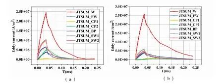
Figure 8.Eddy current in components of inboard (a) and outboard (b) blankets in case 1.
The Lorentz force on the structural components and the PbLi is calculated using the multi-step method.Figures 9 and 10 show the Lorentz forces on different components in two cases.The Lorentz force acting on the structural components along the radial direction (Fx) is much stronger than those along the polar (Fy) and the toroidal directions (Fz).It increases sharply within a very short period of time after the plasma disruption event and it reaches the maximum at about 36 ms.After the peak,it decays slowly and eventually decays to 0.Similarly,the Lorentz force acting on PbLi is mainly distributed in the x direction.However,the Lorentz force in the x direction rapidly increases to the extremum,then it decreases to zero and increases in the opposite direction to a maximum value.Finally,it decays to zero.In case 1,Fxof PbLi in inboard blanket reaches the extremum at 25 ms and the maximum at 50 ms,while Fxof PbLi in outboard blanket gets the extremum at 4 ms and the maximum at 30 ms.This is mainly due to the inconsistent relative growth rate of the vortices in the PbLi in the three directions.The eddy current in the x direction grows relatively fast because of the magnetic induction lines under MD events.After that,it grows slowly because of the effect of the eddy current in RAFM steel and the self-induction phenomenon.Thus,the Fxincreases at first,then the Fxdecreases to 0 and increases in the opposite direction.In the end,the eddy current in the PbLi decays to zero,as the eddy current in the RAFM steel decreases.In case 1,the maximum Lorentz force of RAFM steel in inboard blanket is 7226 kN and it is 3048 kN in outboard blanket.The maximum Lorentz force of PbLi in inboard blanket is 1164 kN and it is 694 kN in outboard blanket.In case 2,the maximum Lorentz force of RAFM steel in inboard blanket is 5624 kN and it is 2360 kN in outboard blanket.The maximum Lorentz force of PbLi in inboard blanket is 567 kN and it is 566 kN in outboard blanket.Because of the FCI,the maximum Lorentz force on structural components of the blanket segments is reduced by approximately 20 percent.The FCI is one necessary component for the COOL blanket to reduce Lorentz force both in RAFM and PbLi.

Figure 9.Lorentz force in RAFM (a) and PbLi (b) of blankets in case 1.
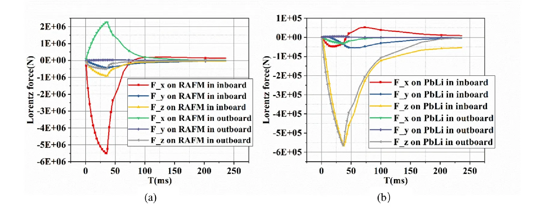
Figure 10.Lorentz force in RAFM (a) and PbLi (b) of blankets in case 2.
4.8.Torque result
The center of the MF backplate is chosen as the reference point in both inboard and outboard blankets.The reference point is at point (3.091,0,0.384) in inboard blanket to calculate the torque,and it is point (10.88,0,0) in outboard blanket.Figure 11 shows the distribution curve of torque in blanket segments.The torque on the inboard blanket segments is greater than that on the outboard blanket segments,and the torque along the z direction (Fx) and y direction (Fy) are much stronger than Fz.It reaches the maximum of 24010 kN·m at 36 ms in inboard blanket and it reaches the maximum of 6322 kN·m at 36 ms in outboard blanket segments in case 1.It reaches the maximum of 31451 kN·m at 36 ms in inboard blanket and it reaches the maximum of 12371 kN·m at 36 ms in outboard blanket in case 2.The maximum eddy current is at the edge of the FWs in case 2,and it is in the middle of the SWs in case 1,and the reference points selected for the calculation are at the center of the back plate in MF in both two cases.So,the maximum torque in case 2 is higher than it in case 1,which is calculated by the formula (4).
5.Summary
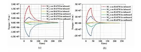
Figure 11.Torque in RAFM of blankets in case 1 (a) and case 2 (b).
In this work,the static magnetic analysis has been performed to calculate the Maxwell.The Maxwell force on the inboard blanket segment is 8434 kN and it is 3447 kN on the outboard blanket segment.The Maxwell force of inboard and outboard blankets is mainly distributed in the radial direction.Then multi-step and magnetic vector methods have been combined to calculate the Lorentz force.The maximum Lorentz force on RAFM steel in inboard blanket segment is 5624 kN and it is 2360 kN on RAFM steel in outboard blanket segment.It can be identified that the FCI is necessary to reduce Lorentz force in the structural components and PbLi by comparing the two cases.The maximum Lorentz forces on structural components of the inboard and outboard blankets are reduced by 21 percent and 22 percent,respectively.The electromagnetic loads as one of the essential mechanical loads will be applied in further structural analysis of the COOL blanket to assess its mechanical performance.
6.Acknowledgments
This work was supported by the Comprehensive Research Facility for Fusion Technology (CRAFT) Program of China(No.2018-000052-73-01-001228) and National Natural Science Foundation of China (No.12205330).
猜你喜欢
杂志排行
Plasma Science and Technology的其它文章
- Laser-induced plasma formation in water with up to 400 mJ double-pulse LIBS
- Plasma nitrogen fixation system with dual-loop enhancement for improved energy efficiency and its efficacy for lettuce cultivation
- Influence of the position relationship between the cathode and magnetic separatrix on the discharge process of a Hall thruster
- A spatiotemporal evolution model of a short-circuit arc to a secondary arc based on the improved charge simulation method
- Different bactericidal abilities of plasmaactivated saline with various reactive species prepared by surface plasmaactivated air and plasma jet combinations
- Modification of streamer-to-leader transition model based on radial thermal expansion in the sphere-plane gap discharge at high altitude
