Influence of the position relationship between the cathode and magnetic separatrix on the discharge process of a Hall thruster
2024-03-18XifengCAO曹希峰HongningMA麻洪宁GuojunXIA夏国俊HuiLIU刘辉FangzhouZHAO赵方舟YuhangWANG王宇航andJuhuiCHEN陈巨辉
Xifeng CAO (曹希峰) ,Hongning MA (麻洪宁) ,Guojun XIA (夏国俊) ,Hui LIU (刘辉) ,Fangzhou ZHAO (赵方舟) ,Yuhang WANG (王宇航) and Juhui CHEN (陈巨辉)
1 School of Mechanical and Power Engineering,Harbin University of Science and Technology,Harbin 150001,People’s Republic of China
2 Shanghai Institute of Satellite Engineering,Shanghai 20040,People’s Republic of China
3 Lab of Plasma Propulsion,Harbin Institute of Technology,Harbin 150001,People’s Republic of China
Abstract Previous studies have shown that there is an obvious coupling relationship between the installation location of the external cathode and the magnetic separatrix in the plume region of a Hall thruster.In this paper,the particle-in-cell simulation method is used to compare the thruster discharge process under the conditions of different position relationships between the cathode and the magnetic separatrix.By comparing the distribution of electron conduction,potential,plasma density and other microscopic parameters,we try to explain the formation mechanism of the discharge difference.The simulation results show that the cathode inside and outside the magnetic separatrix has a significant effect on the distribution of potential and plasma density.When the cathode is located on the outer side of the magnetic separatrix,the potential above the plume region is relatively low,and there is a strong potential gradient above the plume region.This potential gradient is more conducive to the radial diffusion of ions above the plume,which is the main reason for the strong divergence of the plume.The distribution of ion density is also consistent with the distribution of potential.When the cathode is located on the outer side of the magnetic separatrix,the radial diffusion of ions in the plume region is enhanced.Meanwhile,by comparing the results of electron conduction,it is found that the trajectories of electrons emitted from the cathode are significantly different between the inner and outer sides of the magnetic separatrix.This is mainly because the electrons are affected by the magnetic mirror effect of the magnetic tip,which makes it difficult for the electrons to move across the magnetic separatrix.This is the main reason for the difference in potential distribution.In this paper,the simulation results of macroscopic parameters under several conditions are also compared,and they are consistent with the experimental results.The cathode is located on the inner side of the magnetic separatrix,which can effectively reduce the plume divergence angle and improve the thrust.In this paper,the cathode moves from R=50 mm to R=35 mm along the radial direction,the thrust increases by 3.6 mN and the plume divergence angle decreases by 23.77%.Combined with the comparison of the ionization region and the peak ion density,it is found that the main reason for the change in thrust is the change in the radial diffusion of ions in the plume region.
Keywords: Hall thruster,cathode,magnetic separatrix
1.Introduction
A Hall thruster is an electrical propulsion equipment applied to spacecraft altitude control and position maintenance.It has the advantages of a simple structure and long service life[1-4].Figure 1 shows the schematic diagram of a Hall thruster.The radial magnetic field is formed through the inner and outer coils or magnets,and the potential difference between the anode and cathode forms an axial electric field.The electrons emitted from the cathode move towards the anode under the action of the electromagnetic field,and through the collision with the atoms,the atoms are ionized into ions.The ions form thrust under the acceleration of the electric field.The cathode is one of the main components of a Hall thruster.It is responsible for supplying electrons to the thruster discharge and neutralizing the plume.Previous studies have shown that the working fluid flow,current,installation position and other parameters of the cathode can have a significant impact on the thruster discharge performance[5-10].Among them,research on the installation position of the cathode is relatively extensive.However,previous studies have shown that the installation position of the cathode not only needs to consider the relationship between the installation positions of the cathode and thruster,but also needs to consider the matching between the cathode and the magnetic field and other factors [11-13].
To resolve the coupling problem between the magnetic field and the cathode,some scholars have carried out research on the position relationship between the magnetic separatrix and the cathode.Sommerville et al found that the change in the position relationship of the cathode and the magnetic separatrix has a significant effect on the distribution of plasma parameters in the near-field region [11].Ding et al compared the thruster performance difference under various external magnetic pole conditions [12].The results show that the adjustment of the cathode position will affect the discharge current oscillation,plume divergence and other parameters.Meanwhile,the cathode plume is also obviously different.When the cathode is located on the outer side of the magnetic separatrix,the cathode emits light outwards,which appears pink.When the cathode is located within the magnetic separatrix,the cathode forms a distinct plasma bridge towards the beam region.Meng et al also carried out related experimental studies.They moved the cathode through the magnetic separatrix in the radial direction [13].During the movement of the cathode,the thruster plume mainly exhibits two changes.First,as the cathode crosses the magnetic separatrix,the divergence degree of the plume becomes significantly smaller.Second,the pink-glowing torus on the thruster flanks quickly disappears,as shown in figure 2.
The experimental research that has been carried out mainly focuses on the impact of the change of the cathode position on the discharge performance of the thruster,mainly based on the difference in macroscopic parameters.Due to the limitations of experimental research,it is impossible to further study the influence of the cathode position of the inner and outer sides of the magnetic separatrix on microscopic parameters such as electron conduction.Therefore,it is necessary to use simulation to help us better understand the changes in microscopic parameters.Matyash et al used the PIC method to simulate the operation of a 100 W CHT thruster [14].The results show that the initial position of the spoke is strongly correlated with the cathode placement.Meng et al used the fluid simulation method to simulate the distribution of electron streamlines in the coupling region,and compared and analyzed the difference in the electron pressure drop in the coupling region [15].The results show that the change of position relationship between the cathode and the magnetic separatrix will cause a significant difference in the formation position of the virtual cathode,which is the main reason for the difference in coupling voltage drop.
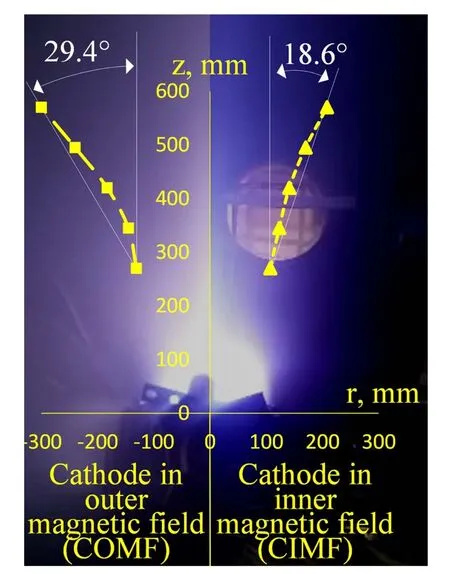
Figure 2.Changes in plume shape during the cathode crossing the separatrix [13].
At present,there are relatively few simulation studies,and the simulations that have been carried out also focus on the coupling region,and have not carried out in-depth research on the microscopic parameters such as the electron conduction and plasma distribution in the main beam region.However,discussing the impact of different cathode positions on a Hall thruster is beneficial to the design optimization of Hall thrusters,and can also provide a theoretical basis for experimental research,which is worth discussing.Therefore,the PIC method is used to study the influence of the position relationship between the cathode and magnetic separatrix on the thruster discharge process in this study.Through simulation,we can obtain microscopic parameters and macroscopic performance parameters,and clarify the influence of cathode position changes on the discharge process by analyzing the results.The rest of this paper is organized as follows: the second part introduces the calculation model,the third part discusses and analyzes the simulation results,the fourth part is the conclusion.
2.Numerical model
Since Hall thrusters are considered to be axisymmetric,a simplified 2D axisymmetric model is used in this paper.Figure 3 shows the calculation region,including the channel and near-field plume region,and the particle types considered in this paper include Xe atom,electron and Xe+ion.We use the leapfrog method with second-order accuracy developed by Boris to solve the Newton equation and obtain the particle motion [16].The particle collision is solved by the Monte Carlo method (MCC).The collisions include elastic,excitation and single ionization.The collision cross-section data are taken from Szabo’s PhD thesis [17].In addition,Bohm anomalous conduction is considered in the model,with Bohm collision frequency νB=CBeB/me,where CBis a semi-empirical coefficient with a value of 1/256 in the channel and 1/64 outside the channel,e is the unit charge,B is the magnetic field intensity and meis the electron mass.

Figure 3.Computational domain and boundary.R1 is the channel inner radius,R2 is the channel outer radius,R3 is the calculation region radial length,L1 is the channel axial length and L2 is the calculation region radial length.
The electric field is treated using the Poisson equation,which is as follows:
Among them,r and z represent the axial and radial directions,respectively.φ is the potential,and,niand neare the ion density and electron density,respectively,e is the unit charge and ε0is the vacuum dielectric constant.
We use the dynamic alternating direction implicit(DADI) method to solve the Poisson equation.The ‘dynamic’ADI method was developed by Said Doss [18],involving a computerized strategy for completely automatic change of the iteration parameter Δt in ADI methods for linear or nonlinear elliptic equations.
Since the magnetic field changes very little,this work simplifies the magnetic field to a fixed distribution.Atpresent,many kinds of thrusters have been studied using this model,such as the Hall thruster [19-26],TAL thruster [27],etc.

Table 1.Treatment of different boundaries.
The boundary conditions involved in the calculation model include the anode boundary,cathode boundary,dielectric boundary,metal wall boundary,free boundary and symmetry boundary,as shown in figure 3.Table 1 summarizes the treatment methods of different boundaries.
Meanwhile,since the ceramic wall material of the channel is generally BN ceramic,the collision between the wall and electrons is treated using the secondary electron emission model (SEE) as follows [26]:
where εeis the electron incident energy,and W0,Wr,W2and W1are the probabilities for the incident electron to be absorbed,to be elastically reflected,to yield two true secondary electrons and to yield one true secondary electron,respectively.The coefficients in equation (2) are set at P0=0.5,α0=43.5 eV,Pr=0.5,αr=30 eV and α2=127.9 eV,and they are fitted based on the experimental results of the SEE characteristics of BN ceramics [26].
The hollow cathode is an important part of a Hall thruster,which provides electrons to the device.Since the cathode destroys the cylindrical symmetry of the model,previous 2D simulations have simplified the cathode boundary to the injection boundary,including the exit boundary [28],plume boundary [29] and electron injection region at the exit of the channel [30].The number of electrons injected in each cycle is determined by a quasi-neutral model or a fixed current model [17].Injected electrons are generally treated using fixed energy combined with a half-Maxwellian model[28].
In this study,we also use electron injection boundary to replace the real cathode,as shown in figure 3.We have adjusted the cathode boundary to allow it to move radially,which is convenient for our research.Meanwhile,the cathode boundary adopts a feedback model,the number of electrons is determined by the anode current obtained from the previous calculation cycle,and the number of electron injections per calculation cycle is obtained by,
where Ianodeis the anode current,w is the real number of particles represented by simulated particles and Δt is the time step.
This feedback model is based on the principle that the cathode current and anode current are equal,which is more consistent with the discharge process of the thruster compared to the quasi-neutral model and the fixed current model.However,in the early stage of the simulation,the quasi-neutral model or the fixed current model needs to be used as the model of the initial electron injection,because at the beginning of the program calculation,the anode current is 0 A,and so the feedback model cannot be used.In the program,we set a switching condition.When the anode current reaches the predetermined current,the cathode boundary continues to be calculated using the feedback model.Generally,we use Ianode=1 A as the switching condition.The electron injection method used in this paper is a combination of the quasi-neutral model and the feedback model.The quasi-neutral model is based on the statistics of the number of electrons in the corresponding grids.When the number of electrons is less than the number of ions,electrons are injected into the calculation area.The calculation equation is as follows:
where Niis the number of ions in a grid,Neis the number of electrons in a grid and jmaxis the total number of meshes for the cathode boundary.
In this study,the energy of injected electrons is treated as 2 eV [31,32],and the velocity distribution adopts half Maxwell distribution.The capacitive charging model is used for the metal wall boundary.The capacitance is estimated to be C=1 × 10⁻⁸F.
FEMM software is a finite element method magnetic software,which is used to calculate 2D and axisymmetric finite element electromagnetic and other related problems.In this study,FEMM software is used to solve the magnetic field distribution.To comprehensively analyze the discharge difference under different external cathode positions,we choose a magnetic field with a magnetic separatrix.The location of the magnetic separatrix is shown in figure 3.We select four radial cathode positions R=35,40,45 and 50 mm inner and outer sides of the magnetic separatrix.
This work establishes the calculation model based on the MaSMi-EM Hall thruster in the literature [33].We simplify the thruster channel to a straight channel structure.The calculation parameters are shown in table 2.

Table 2.The calculated region parameters.

Figure 4.Two-dimensional distribution of potential under four radial cathode positions (V).(a) R=35 mm,(b) R=40 mm,(c) R=45 mm,(d) R=50 mm.
3.Simulation results and analysis
3.1.Potential and plasma density
Figure 4 shows the potential distribution under the four conditions.It is found that there are obvious differences in potential distribution under the four conditions.As the cathode position moves from the inner to the outer side of the magnetic separatrix,the potential difference between the upper and lower parts of the plume region will gradually increase.For case R=35 mm,the potential distribution is relatively symmetrical in the radial direction.However,for case R=50 mm,in the radial direction,the potential distribution is not symmetrical,and the potential near the axisymmetric side is relatively high.As a result,there is a relatively strong upward-directed potential gradient in the radial direction of the plume.This strong radial potential gradient is more conducive to the radial diffusion of ions in the plume region above,thereby increasing the plume divergence angle.
3.2.Electron conduction distribution
To explain the difference in potential distribution,we further compared the difference in electron conduction.Here,we use the electron mobility model in the literature,and the equation is as follows [34-36]:
µeffis the effective electron mobility,k is the Boltzmann constant,Ezis the axial electric field and Teis the electron temperature.je⊥is the electron current density,the direction perpendicular to the magnetic field,je⊥=-eneu⊥,neis the electron density and u⊥is the electron velocity.
To compare the effect of the magnetic field on electron mobility more intuitively,the influence of classical collision between electrons and other particles is ignored in the simulation,and only the influence of Bohm conduction is considered.The electron mobility distribution under different cathode position conditions is shown in figure 5.
By comparing the electron mobility,it is found that the distribution shape of the electron mobility is similar to the distribution shape of the magnetic field,which is related to the movement of electrons around the magnetic field lines.At the same time,under the condition of different cathode positions,there are obvious differences in the distribution of electron conduction.For case R=35 mm,the electron mobility is relatively uniform on both sides of the thruster outlet.However,for case R=40-50 mm,the electron mobility on the side of the symmetry axis is relatively low.With the upward movement of the cathode position,the peak region of electron mobility also gradually moved above the plume region.
The main reason for the difference in electron conduction distribution is that it is difficult for electrons to cross the magnetic separatrix effectively.As shown in figure 6,it is found from the trajectory of a single electron that when the electron moves along the magnetic field line towards the magnetic tip on the outer magnetic pole,it will be reflected to its incident region.This phenomenon can be explained by the magnetic mirror effect.It is precisely because of the significant differences in electron motion that lead to differences in electron conduction.
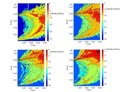
Figure 5.Two-dimensional logarithmic normalized distribution of electron mobility in the plume region under four conditions.(a) R=35 mm,(b) R=40 mm,(c) R=45 mm,(d) R=50 mm.
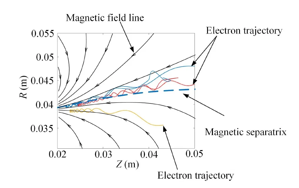
Figure 6.The trajectories of electrons on the inner and outer sides of the magnetic separatrix.
The stronger the electron conduction,the smaller the potential gradient change [37].Therefore,for case R=35 mm,since the radial distribution of electron mobility is relatively symmetrical,the potential distribution is also relatively symmetrical under this condition.When the cathode is located on the outer side of the magnetic separatrix,the electron mobility above the plume region is relatively strong,resulting in a relatively low potential in this region and an asymmetric potential distribution in the radial direction.
Meanwhile,through the distribution of electron mobility,it is found that when the cathode is located on the outer side of the magnetic separatrix,the magnetic field outside the magnetic separatrix captures the electrons emitted from the cathode,and electron trajectories will also move along the magnetic induction lines towards the outside.Due to the low energy of this part of the electrons,the collisions with atoms are mainly excited collisions.Consequently,a pink-glowing torus will be observed in the experiment.When the cathode is located on the inner side of the magnetic separatrix,this phenomenon does not occur,as shown in figure 2.
3.3.Ion density distribution
Since there are significant differences in the potential distribution,this will affect the distribution of ions.Therefore,figure 7 further compares the ion density distribution in the plume region.The simulation results indicate that the ionization zone is mainly located inside the channel,and the peak ion density is in the order of 1018m-3,which is consistent with the results in the literature [38].In addition,it is found that there is no significant difference between the ionization zone position and the peak ion density under the four cathode position conditions.Therefore,the relationship between the cathode and the magnetic separatrix does not have a significant effect on ionization in the channel.At the same time,it is found by comparison that the change of the cathode position has a significant effect on the ion density distribution in the plume region.As the cathode position moved from R=35 mm to R=50 mm,the radial divergence of ion distribution gradually increased.This is because when the cathode is located on the outer side of the magnetic separatrix,the potential above the plume region is relatively low,which is conducive to the radial transport of ions above the plume.

Figure 7.Two-dimensional distribution of ion density under four cathode radial positions (m-3).(a) R=35 mm,(b) R=40 mm,(c) R=45 mm,(d) R=50 mm.
Figure 8 shows the radial distribution of ion flux at Z=0.04 m under the four cathode position conditions.It is found that the ion flux above the plume region decreases gradually with the downward movement of the cathode position.This also verified that the cathode located on the inner side of the magnetic separatrix can indeed restrict the radial diffusion of the plume.
3.4.Comparison of macro parameters

Figure 8.Radial ion flux distribution under four cathode radial positions at Z=0.04 m.
Figure 9 shows the results of thrust and plume divergence angles under four cathode position conditions.We take the thrust with the cathode position at R=50 mm as the reference,and the thrust difference under the four radial position conditions is shown in figure 9(a).With the downward movement of the cathode radial position,the thrust gradually increases.The change trend of the thrust is consistent with the literature [12].For case R=35 mm,the thrust can be increased by up to 3.6 mN.
In this study,we select a simple method to count the half plume divergence angle.We count the ion flux on the right boundary and find the radial position where the ion flux accounted for 90%,and then we obtain the angle between the line of the two points (the radial position and the vertex of the outer channel wall) and the axis direction,and this angle is approximated as the half plume divergence angle.Through statistics of the plume divergence angle,it is found that the plume divergence angle decreases significantly with the downward movement of the cathode radial position,as shown in figure 9(b).The angle changes between 32° and 41.9°,and this result is basically consistent with the measurement results in the literature [39].Compared with case R=50 mm,the plume divergence angle can be reduced by 23.77% for case R=35 mm.The change trend of the plume divergence angle is consistent with previous analysis [12,13].Combined with the distribution of ion density,the change of thrust is mainly caused by the change in the radial divergence of ions in the plume region.
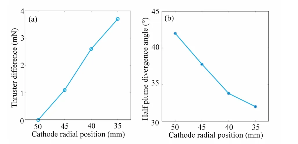
Figure 9.Comparison of thrust and half plume divergence angle under four cathode radial positions.(a) Thruster difference,(b) half plume divergence angle.
4.Conclusion
This paper simulates and discusses the effect of the position relationship between the cathode and the magnetic separatrix on the discharge of the Hall thruster.Research results indicate that the trajectories of electrons emitted from the cathode are significantly different on the inner and outer sides of the magnetic separatrix,resulting in differences in electron conduction and potential distribution.When the cathode is located on the outer side of the magnetic separatrix,the potential above the plume region is relatively low,and the potential gradient in the radial direction is large.As a result,the radial divergence of ions in the plume region is strong.By comparing the macroscopic parameters,it is found that when the cathode is located on the inner side of the magnetic separatrix,the plume divergence angle is relatively small,which is consistent with previous experimental results.Combined with the comparison of the ionization region and the peak ion density,it is established that the main reason for the change in thrust is the change in the radial diffusion of ions in the plume region.
Acknowledgments
This work was supported by the Shanghai 2022 Science and Technology Innovation Action Plan (No.22YF1446800).
猜你喜欢
杂志排行
Plasma Science and Technology的其它文章
- Ion-acoustic waves with non-planar wavefronts
- Gyro-Landau-fluid simulations of impurity effects on ion temperature gradient driven turbulence transport
- Investigation on the roles of equilibrium toroidal rotation during edge-localized mode mitigated by resonant magnetic perturbations
- Gyrokinetic simulation of magnetic-islandinduced electric potential vortex mode
- Modification of streamer-to-leader transition model based on radial thermal expansion in the sphere-plane gap discharge at high altitude
- Different bactericidal abilities of plasmaactivated saline with various reactive species prepared by surface plasmaactivated air and plasma jet combinations
