Hydrogen inhibition effect of chitosan and sodium phosphate on ZK60 waste dust in a wet dust removal system: A feasible way to control hydrogen explosion
2023-11-18YuyunZhngKiliXuJihunLiBoLiuBenWng
Yuyun Zhng, Kili Xu,b,∗, Jihun Li, Bo Liu,b,∗, Ben Wng
a College of Resources and Civil Engineering, Northeastern University, Shenyang 110819, China
b Key Laboratory of Ministry of Education on Safe Mining of Deep Metal Mines, NO. 3-11
Received 1 August 2021; received in revised form 27 September 2021; accepted 10 November 2021
Available online 13 December 2021
Abstract Wet dust removal systems used to control dust in the polishing or grinding process of Mg alloy products are frequently associated with potential hydrogen explosion caused by magnesium-water reaction. For purpose of avoiding hydrogen explosion risks, we try to use a combination of chitosan (CS) and sodium phosphate (SP) to inhibit the hydrogen evolution reaction between magnesium alloy waste dust and water. The hydrogen evolution curves and chemical kinetics modeling for ten different mixing ratios demonstrate that 0.4wt% CS + 0.1wt%SP yields the best inhibition efficiency with hydrogen generation rate of almost zero. SEM and EDS analyses indicate that this composite inhibitor can create a uniform, smooth, tight protective film over the surface of the alloy dust particles. FTIR and XRD analysis of the chemical composition of the surface film show that this protective film contains CS and SP chemically adsorbed on the surface of ZK60 but no detectable Mg(OH)2, suggesting that magnesium-water reaction was totally blocked. Our new method offers a thorough solution to hydrogen explosion by inhibiting the hydrogen generation of magnesium alloy waste dust in a wet dust removal system.© 2021 Chongqing University. Publishing services provided by Elsevier B.V. on behalf of KeAi Communications Co. Ltd.This is an open access article under the CC BY-NC-ND license (http://creativecommons.org/licenses/by-nc-nd/4.0/)
Keywords: ZK60 waste dust; Hydrogen inhibition; Wet magnesium alloy waste dust collection system; Chitosan; Sodium phosphate.
1. Introduction
Mg is a resource-rich, inexpensive metal widely found across the globe.Recently,Mg alloys have attracted wide concern for their superior properties [1]. Polishing and grinding,as two indispensable processes in the machining of Mg alloy products, often produce huge amounts of small-sized explosive waste Mg alloy dust which is not only inflammable, but also harmful to the human body and farm crops [2]. Although wet dust removal systems and hydrogen alarm devices are installed at many waste Mg alloy dust generating sites to avoid potential dust explosion related to dry dust removal[3],as Mg alloy dust particles can constantly give off hydrogen and heat upon exposure to water and, in the event of poor ventilation or a failed alarm system, hydrogen can accumulate up to the minimum concentration for hydrogen explosion, unexpected explosions can break out any time, as has been evidenced by some explosion accidents in dust collectors. On March 8,2011, a hydrogen explosion at the casing workshop of a precision fabrication company in Zhenjiang of China’s Jiangsu province left 21 injured when water was sprayed through the wet dust collector pipe to reduce dust and hydrogen was generated as soon as the Mg dust came into contact with water[4]. According to our hydrogen test on wet Mg alloy dust collectors at industrial sites, inside a wet dust collector, hydrogen can be generated constantly and rapidly.In the absence of forced ventilation, it takes only 72 h for the hydrogen in the wet dust collector to reach the minimum concentration for hydrogen explosion, 104ppm; even in the presence of regular ventilation, hydrogen can occasionally accumulate to a very high level, too. At present, technical measures against hydrogen explosion in wet Mg alloy dust removal systems typically include means to prevent the formation of a hydrogen explosion environment or to control the ignition sources. These measures involve a lot of technical and energy resources, yet they still cannot preclude the explosion risks in wet Mg alloy dust removal systems from the source. If hydrogen generation could be inhibited, wet dust removal systems would be essentially liberated from hydrogen fire and explosion. To this end,this paper tries to deal with hydrogen explosion risks by inhibiting hydrogen generation in a wet Mg alloy dust removal system.
So far, studies on dust explosion inhibition have mostly relied on the addition of an amount of an inert medium to disrupt the five factors of dust explosion [5,6]. However, the majority of the inhibitors are not suitable for a wet Mg alloy dust removal system since they will accelerate the Mg-water reaction after entering water along with the Mg alloy dust,thus adding to the possibility of hydrogen explosion [7]. Hydrogen generation caused by Mg-water reaction is arguably a hydrogen-evolution process of Mg alloys. Yet previous authors have mostly been concerned about the overall corrosion protection of large areas of Mg alloy plate [8–10]. Many plate preservatives do not work for powdered Mg alloy dust,which has large specific surface areas, stronger reactions and can generate huge amounts of hydrogen within a short time.In recent years, a few authors have examined how to inhibit hydrogen generation caused by Al-water reaction. Xu et al.[11,12] presented an HIM-based hydrogen inhibition method for wet dust collectors. They discovered that CeCl3inhibits Al-water reaction by creating a precipitation film over the surface of Al particles to block this reaction. Wang et al.[3,13] demonstrated that organic inhibitors such as soybean isoflavones and calcium D-gluconate can inhibit Al-water reaction by adsorbing on the surface of Al particles through van der Waals force, thus blocking this reaction. However, as Mg has a limited number of empty orbits available, it is more difficult for Mg to lose or obtain electrons than Al, and Mg is more susceptible to corrosion and oxidation than Al [14].Yet nobody has looked at the inhibition of hydrogen generation caused by Mg-water reaction up to the present day. In a word, no researchers have studied the hydrogen explosion associated with Mg alloy dust when in contact with water in a wet dust removal system. The research on the inhibition of hydrogen generation by inerting Mg-water reaction is still a blank field. In this paper, we will consider using a combination of organic and inorganic materials to create a protective film over the surface of waste Mg alloy dust particles so as to inhibit hydrogen generation and improve the intrinsic safety of the wet dust removal system in the machining of Mg alloys.
Chitosan (CS) is a high molecular weight carbohydrate widely used as a metal and alloy-friendly corrosion inhibitor.In fact, it is one of the most welcomed green inhibitors for its low toxicity [15]. Ansari et al. [16] synthesized an ecofriendly Schiff base by the reaction of CS and salicylaldehydeand validated its corrosion inhibition effect on Mg alloys in 3.5wt% NaCl saturated with carbon dioxide. Phosphates are among the most widely used corrosion inhibitors. They can provide lone pair electrons for many metals very easily. The characteristicP=Odouble bonds contained in them can generate a phosphate film with metals, providing a perfect protection. Hou et al. [17] investigated the joint corrosion inhibition effect of SP and sodium alginate (SA) on AZ31 Mg alloy in NaCl solution. SP and SA can work together to inhibit the corrosion of AZ31. The best corrosion inhibition effect was yielded for AZ31 substrate when 3.5wt%NaCl electrolyte containing 0.05wt% SA and 0.15wt% SP was used. Following their discoveries, we selected CS and SP as a compounded inhibitor to see how they work together to inhibit Mg-water reaction at different concentrations and yield the optimal concentration for inhibiting hydrogen generation reaction. We also established the physio-chemical mechanism underlying this the inhibition.

Tab 1 Combination of inhibitors.
2. Experiment
2.1. Preparation of mg alloy dust and inhibitor(s) containing NaCl solutions
Metal dust particles produced by grinding extruded Mg alloy ZK60 plate, composed of conventional elements (wt%)(Zn 5.587wt%, Mn 0.0139wt%, Al 0.0327wt%, Zr 0.12wt%,Mg balance), were used as the main raw material. NaCl particles were mixed with 200 mL deionized water into 3.5wt%NaCl solution. This NaCl solution was prepared to simulate the water environment in a wet dust collector. According to surveys, wet collectors are often washed with chlorinecontaining disinfectants. As industrial water itself contains a concentration of Cl-, there are a lot of chlorine ions in the water bath of the wet dust collector, too. For this reason,we used 3.5wt% NaCl to simulate the real production environment. The CS selected was a food-grade water-soluble material that is inexpensive and widely available. The NaCl particles and the SP were sourced from Shanghai Macklin Biochemical Co., Ltd. All reagents are of analytical grade and do not need further purification or differentiation. Deionized water was used throughout the experiment. Table 1 gives the experimental scheme used in the study.
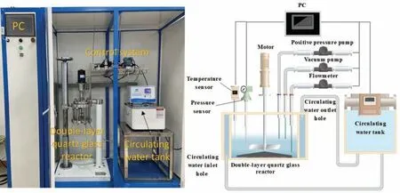
Fig 1. The hydrogen generation test apparatus.
The entire inhibition experiment involved two parts:an experimental group consisting of different concentrations of CS+SP inhibitor solutions, prepared by mixing (0.2wt%, 0.3wt%, 0.4wt%) CS with (0.1wt%, 0.2wt%,0.3wt%, 0.4wt%) SP, respectively, and adding the mixtures into 3.5% wt NaCl solution; and a control group consisting of separate inhibitors and blank inhibitors,including(0.2wt%,0.3wt%, 0.4wt%, 0.75wt%) CS solutions, (0.1wt%, 0.3wt%,0.4wt%, 0.75wt%) SP solutions, and NaCl solution without any inhibitor. Both parts of experiments were performed under same atmospheric conditions.
2.2. Hydrogen conversion measurement
An automatic dust-water reaction hydrogen generation test apparatus (as shown in Fig. 1) was used to simulate the environmental and temperature conditions in a wet dust collector and measure the hydrogen evolution caused by the reaction between alloy dust particles and water. For each group of the experiment,1.5-g waste Mg alloy dust particles were weighed and placed into the filling system of the instrument together with the prepared inhibitor solution. The temperature of the reaction-measuring jacket was 60 °C. The initial pressure was the atmospheric pressure, 100 KPa. For each group the reaction time was set to 24 h, the specified ash removal interval for wet dust collectors. At the end of each group of the experiment, the reacted dust was filtered and washed with a vacuum suction filter device and deionized water and dried in a vacuum dryer at 80 °C for 24 h
Hydrogen generation was measured by calculating the hydrogen conversion rateαof ZK60 waste dust particles in different solutions at any time under a given temperature according to the pressure variation in the hydrogen generation test apparatus (Eq. (2)) based on the ideal gas law (Eq. (1)).
Where:Pis the gas pressure in the reactor, kPa;Vis the reactor volume, L;nis the mole of hydrogen gas, mol;Ris the ideal gas constant, 8.314 J·(mol·K)-1;Tis the temperature, K;αis the hydrogen evolution;Pis the gas pressure in the reactor, kPa;Pinitialis the initial pressure value of the reactor, kPa;Vsolutionis the volume of the solution added into the reactor, L;n0is the mole of aluminum powder added into the reactor, mol.
Pressure is a critical influencing factor for the accurate measurement of experimental results. Before each group of the experiment, an air tightness test was performed at the initial pressure of 300 KPa. The instrument was airtight enough to guarantee true experimental results if the pressure variation is within ±0.1 KPa after 24 h
2.3. Kinetic calculation of reaction
From the findings of Gai et al. [18], the chemical kinetics of the reaction between Mg or Al particles and water can be characterized by the shrinking core model. Using this model,we can obtain the hydrogen generation rate of ZK60 dust particles in different solutions.The relation between hydrogen conversion rateαand hydrogen generation ratekis expressed by Eq. (3):
Where:kis the rate constant,h- 1;tis the reaction time,h.
2.4. Characterization analysis
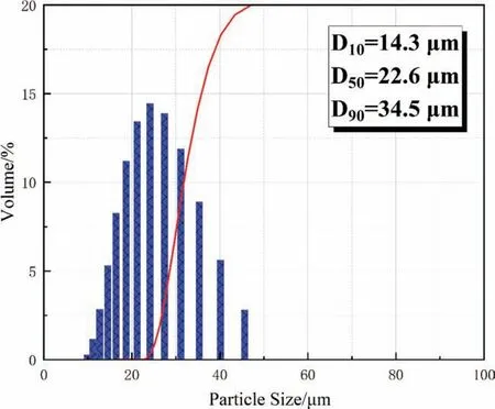
Fig 2. Particle size distribution of ZK60 waste dust particles.
A laser particle size analyzer (Mastersizer 3000) was used to characterize the size distribution of ZK60 dust particles.A scanning electron microscope (SEM) and an energy dispersive spectrometer (EDS) were used to characterize the morphologies of these dust particles before and after reaction with different inhibitor solutions (3.5wt% NaCl, 0.4wt%CS+0.2wt% SP, 0.75wt% CS, 0.75wt% SP), and the Mg and O atomic percentages in the reaction products. A Fourier transform infrared spectroscope (FTIR, Nicolet iS10) was used to analyze the functional groups in the reaction products between ZK60 waste dust particles and different solutions(0.4wt% CS+0.2wt% SP, 0.75wt% CS). In order to better understand the phases of the products, an X-ray diffractometer(MPDDY2094, PANalytical B.V.) was used to analyze the reaction products between ZK60 dust particles and different solutions (3.5wt% NaCl, 0.4wt% CS+0.2wt% SP, 0.75wt%SP).
3. Results
3.1. Size distribution of ZK60 waste dust particles
Figure 2 shows the size distribution of ZK60 waste dust particles. The size is more concentrated at 22.6 μm, being 14.3 μm, 22.6 μm, and 34.5 μm at d10, d50, and d90.
3.2. Effect of the inhibitors on the hydrogen evolution of ZK60 waste dust particles
Figure 3 records the hydrogen conversion rates of ZK60 waste dust in 3.5wt%NaCl solutions containing different concentrations of inhibitors (CS and SP) and without any inhibitor, as a function of time. Figure 3(a–d) include a blank control group containing no inhibitor. In the absence of an inhibitor, hydrogen evolution started the moment the ZK60 waste dust comes into contact with water.
The overall reaction proceeds in two stages. The first is a rapid reaction stage, when the Mg on the surface of the dust particles reacts with water, as expressed by Eq. (4-6). During this period, a large amount of hydrogen is rapidly evolved.The small amount of Zn in ZK60, which acts as a primary battery, will accelerate hydrogen evolution at the beginning,giving off a lot of hydrogen. The second is a slow hydrogen production stage, when the reaction expressed by Eqs. (7-8)takes place. During this period, the hydrogen evolution rate is much slower and the duration is longer, making up around 80% of the whole reaction. Hydrogen diffuses slowly out of the interior of the particles until the reaction draws to an end.At that time, NaCl will play two roles in the solution. Firstly,it acts as a salt bridge in the reaction. Since the ions in the solution gradually decrease after the reaction of Mg2+and H2O, the speed of conducting electrons slows down, while NaCl can conduct electrons to further the reaction. Second, it can reduce the pH of the solution and increase the erosivity of the medium. Over time, the Mg(OH)2film formed over the surface of the particles becomes thicker.The breakdown effect of Cl-on this Mg(OH)2film becomes weaker. The hydrogen generation rate gradually slows down.

Fig 3. Hydrogen evolution curve of the reaction of ZK60 particles with (a) CS+SP, (b) CS, (c) SP and (d) Comparison of suppression effects.
Figure 3(a) compares the hydrogen evolution curves of ZK60 waste dust at different CS+SP mixing ratios. After the two inhibitors are added, the hydrogen generation reaction is markedly weaker. A closer look will find that the inhibition effect is better when the proportion of CS is greater than that of SP. The three best combinations are 0.4wt% CS+0.1wt%SP, 0.4wt% CS+0.2wt% SP, 0.3wt% CS+0.2wt% SP. The hydrogen evolution curves are almost parallel to the x axis.
Figure 3(b)–(c) compare the hydrogen evolution curves when CS and SP are used separately. CS and SP, when separately used, can each inhibit the hydrogen evolution of ZK60 waste dust to some extent, but neither of them can fully prevent this reaction, although SP is better able to inhibit hydrogen generation than CS. As the inhibitor concentration increases, the hydrogen evolution of ZK60 waste dust reduces markedly in the CS solution but does not change much in the SP solution.
Figure 3(d)compares the optimal concentrations of CS and SP when used together and when used separately. The hydrogen evolution of ZK60 waste dust is the lowest in the 0.4wt%CS+0.2wt% SP solution; the hydrogen evolution reaction has almost stopped. The experimental results indicate that when used together, CS and SP can effectively inhibit the reaction between Mg alloy dust particles and water.
3.3. Surface morphology
Figure 4 compares the particle surface morphologies of ZK60 waste dust before and after reaction in 3.5wt% NaCl solutions, which contain different concentrations and mixing ratios of inhibitors. Before reaction, the ZK60 waste dust (a and A) has smooth surface and regular shape. After reaction with water (b and B), the particle surface becomes rough and petals out. According to previous studies, when an Mg alloy is exposed to water, a series of hydrogen generation will take place to generate Mg(OH)2, as expressed by Eqs. (4-8). The Mg(OH)2so generated, as a protective film, will to some extent protect the alloy particles from corrosion. However, as this film is porous and very thin and brittle, its protection for the Mg alloy substrate is very limited. The Cl-content in the solution will also penetrate the pores and expose the Mg alloy to constant pitting. Consequently, external water molecules will enter through the Mg(OH)2film and continue to react with the Mg inside to generate H2which will then accumulate beneath the Mg(OH)2film. When the pressure increases to the critical limit, the H2inside will burst out of the Mg(OH)2film, creating the petal-like surface shape of the reacted particles.
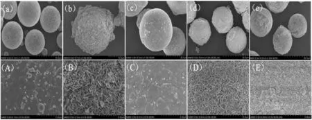
Fig 4. SEM micrographs of Mg alloy ZK60 before (a and A) and after (b and B) reaction in neat 3.5wt% NaCl solution, and those containing various inhibitor concentrations: (c and C)0.4wt%CS + 0.1wt% SP, (d and D) 0.75wt% CS, (e and E) 0.75wt% SP.

Tab 2 Results of EDS analysis.
Figure 4(c–e) compare the morphologies of the reaction products after the inhibitors are added. When CS (d and D)and SP(e and E)are each added separately,the particle surface tends to be smoother but is still rough. A separate inhibitor can inhibit the hydrogen generation of ZK60 to some extent but the effect is some distance from being ideal. This is because when CS and SP act alone, they cannot completely cover the surface of ZK60 alloy dust particles, resulting in some Mg particles exposed to the outside and reacting with water molecules, which makes the particle surface rough. Hydrogen is still precipitating constantly. The curves in Fig. 3(b,c) also support this observation. From EDS analysis, as presented in Table 2, the O content in the product is fairly high.When SP is used, the O content is lower than when CS is used, further confirming that SP is better able to inhibit hydrogen generation than CS. Fig. 4(c) shows the morphology of the product when both SP and CS are used. The particles have smooth surface and regular shape. Their morphology is almost the same as before reaction. At that time the O content is only 9.58%. Besides, 4.48% N and 1.28% P are also detected. This demonstrates that a combination of SP and CS can create a protective film over the surface of Mg alloy waste particles, thus blocking the reaction between external water molecules and the Mg waste particles inside.
3.4. FTIR
Figure 5(a) shows the molecular structure of CS [16]. The main functional groups are -C-O–C, -OH, -NH2, -C-OH, and-CH2. Figure 6 compares the FTIR spectra of CS particles and of ZK60 waste dust after reaction in 0.75wt% CS and 0.4wt% CS + 0.1wt% SP solutions. In the spectral curve of CS Powder, the characteristic peak band at 3448 cm-1is caused by the stretching vibration of -OH and -NH; the peak band at 1632 cm-1relates to the bending vibration of the N–H bond in -NH2; 1432 cm-1corresponds to the variable angle vibration of -CH2; the characteristic peak at 1068 cm-1is produced by the stretching vibration of the C–O in-C-O–C;the peak at 890 cm-1is the stretching vibration peak of the sugar ring.
When an inhibitor is added into the solution, the FTIR spectrum of CS when used separately is roughly the same as that when CS and SP are used together. After CS is added,it acts independently from SP. The two inhibitors do not affect each other. In the reaction product, strong -OH and -NH characteristic peaks appear at 3448 cm-1and 1632 cm-1.The hydroxyl and amino groups in CS have participated in the reaction and chelated with Mg2+. The characteristic peak at 1075 cm-1relates to the stretching vibration of C–O group.The major adsorption is ascribed to the -C-O bond in the glycosidic bond. At 1075 cm-1the energy spectrum broadens and moves towards high frequencies (1068 cm-1–1075 cm-1),suggesting that CS is adsorbed on the surface of ZK60 waste particles.At 1432 cm-1the stretching vibration peak of-CH2disappears, suggesting that CS itself has the crosslinking ability to bind to metal cations.The ring-structured chelate formed by Mg2+and a polydentate ligand of CS limits the stretching vibration of the C–H2bond on the six-membered ring,making the dipole moment variation too small to observe the absorption peak. The appearance of a stretching vibration peak of the sugar ring at 890 cm-1further proves the CS adsorption on the surface of Mg alloy particles.
3.5. XRD

Fig 5. Illustration of molecular structures of (a) SA and (b) SP.
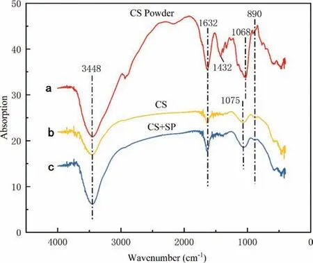
Fig 6. FTIR spectra of CS powder (a) and Mg alloy ZK60 after reaction in (b) 0.75wt% CS, (c) combined of 0.4wt% CS + 0.1wt% SP.
Figure 7 compares the XRD results of the reaction product of ZK60 under three different conditions. When an inhibitor is added, the diffraction peaks of the product are primarily Mg and Mg(OH)2. When separate 0.75wt%SP is added into the solution, the number of diffraction peaks of Mg(OH)2in the product reduces extensively and new diffraction peaks of Mg3(PO4)2appear instead. SP has reacted with ZK60 waste particles to generate a precipitation film. However, as Mg3(PO4)2is not so stable, some Mg alloy particles are still exposed in water to precipitate hydrogen. When 0.4wt%CS+0.1wt%SP is added into the solution, the diffraction peaks of Mg(OH)2in the reaction product totally disappear, leaving behind the diffraction peaks of only Mg and Mg3(PO4)2, which further verifies the inhibition effect of CS and SP on ZK60.
3.6. Chemical kinetics model
Figure 8 compares the reaction rates of ZK60 in separate inhibitor solutions, composite inhibitor solutions, and 3.5wt%NaCl solution based on shrinking core modeling. Obviously,the reaction rates in the solution containing no inhibitor and the solutions containing only one inhibitor are much higher than in a composite inhibitor solution. Calculations also show that the 0.4wt% CS + 0.1wt% SP solution results in the lowest k, 1.726E-4, which is almost zero. Obviously, this is the best CS/SP mixing ratio for inhibiting the reaction between Mg alloy waste particles and water.
3.7. Adsorption model
According to previous studies, adsorption isotherms can describe how inhibitor molecules interact with alloy surfaces[19,20]. These curves can be defined as the variation of the adsorption strength of an inhibitor on the surface of the alloy as a function of inhibitor concentration under the same temperature. In an aqueous solution, the surface of ZK60 waste particles is surrounded and covered by water molecules. In an inhibitor solution, inhibitor molecules are adsorbed on the surface of the alloy particles in place of water molecules.We tried to fit the adsorption curves of CS and SP using multiple isotherm adsorption models such as Langmuir,Temkin, Frumkin, and Flory–Huggins. Only the regression coefficient (R2) from Langmuir isotherm adsorption model is close to 1 (R2(CS)=0.99987, R2(SP)=1), while the values from the other models range from 0.2 to 0.8. Hence we assumed that the adsorption of CS and SP on ZK60 conforms to Langmuir isotherm adsorption model, as expressed by Eq. (9).

Fig 7. XRD results of Mg alloy ZK60 after reaction in (a) 3.5wt% NaCl solution, (b) 0.75wt% SP and (c) combined of 0.4wt% CS + 0.1wt% SP.
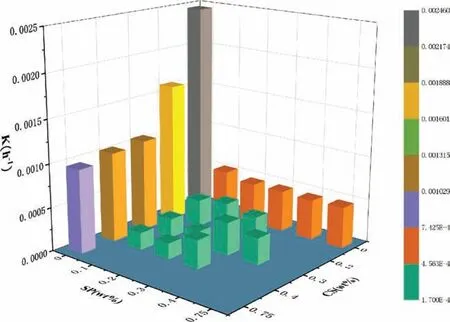
Fig 8. Hydrogen production rate of Mg alloy ZK60 in different solutions.
Where:Cis the mass concentration of inhibitors, g·L-1,Kis the adsorption equilibrium constant, L·g-1, andθis the surface coverage.
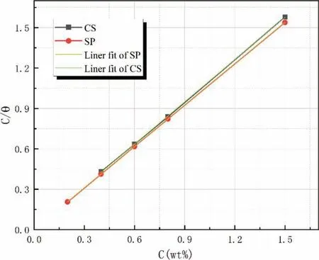
Fig 9. The Langmuir adsorption isotherm curves for CS and SP.

Tab 3 Calculated synergistic parameter (S) for mixtures of CS with SP.
Figure 9 compares the Langmuir isotherm adsorption model curves for CS and SP. The adsorption of these inhibitors on ZK60 is a monolayer adsorption in which the energy is equal among all adsorption sites.
3.8. Synergistic effect
According to the previous research results, the interaction between the two inhibitors includes synergy and antagonism[21]. The former occurs when the effect of the two inhibitors when used together is greater than the sum of their respective effects when used separately. The latter is just the opposite.The synergistic effectSof CS and SP can be calculated by Eqs.(10)and(11).The interaction is synergistic ifSis greater than 1 and antagonistic if otherwise.
Where:θ1is the inhibition efficiency of inhibitor 1 (CS),θ2is the inhibition efficiency of inhibitor 2 (SP), andθ′1+2is the inhibition efficiency of inhibitor 1 and inhibitor 2 when used together. Table 3 gives theSvalues for the CS+SP mixture at the optimal mixing ratio 0.4wt%CS+0.1wt%SP and for each of the two inhibitors (0.4wt% CS, 0.1wt% SP) when used separately, calculated according to Eq. (11). When CS and SP are used together, theSvalue is greater than 1, suggesting that they can produce a synergistic effect when used together.
4. Discussion
4.1. Inhibition effect of CS and SP when used separately
In the NaCl solution, the surface of ZK60 waste particles are wrapped by Mg(OH)2. The pitting by the Cl-content in the solution results in loose, porous structures on the surface of the particles. When an amount of CS is separately added into the solution, according to the Hard-Soft Acid-Base (HSAB) theory, when hard acids are bound with hard bases, electrons are hardly able to transfer and strong ion coordination bonds are formed only by electrostatic process[22]. Mg2+is a hard acid with fairly high positive charge.CS is a hard base with a structure shown in Fig. 5(a). The O element coordination atoms in the methylene, hydroxyl and other complex functional groups in CS, with their high electronegativities, can form a stable complex with hard acids.The large amounts of hydroxyl, methylene and ether bonds on CS react with the Mg2+and reaction product (Mg(OH)2)on the surface of ZK60 waste dust particles to form complex ions, causing the Mg(OH)2of the oxide film to peel off and become a chelate of SA. The reaction equation is as expressed by Eq. (12). However, as the CS molecular chain is quite long and large in volume, it is easily entangled, hence cannot act on all active sites on the surface of the Mg alloy.Consequently, many defects are produced inside the surface film, as is evidenced by SEM analysis (Fig. 4(d)). That is,existence of uncovered active sites prevents the generated product [CS-Mg] from covering the surface of ZK60 waste particles completely.When an amount of SP is separately added into the solution, SP reacts with ZK60 waste particles as expressed by Eq. (13). As Mg3(PO4)2is less soluble than Mg(OH)2, it covers the surface of ZK60 waste particles in place of Mg(OH)2.From the hydrogen evolution curves and SEM analysis of ZK60 in different concentrations of SP solution, due to nonuniformity and local corrosion, the generated Mg3(PO4)2cannot completely cover the surface of ZK60, leaving some of the Mg alloy particles exposed in the NaCl solution to precipitate hydrogen.

Fig 10. Joint inhibition principle of CS and SP.
4.2. Inhibiting effect of CS and SP when used together
Addition of CS and SP into the NaCl solution at a given proportion greatly increases inhibition efficiency. XRD and FTIR analyses indicate that the co-precipitation film on the surface of ZK60 waste particles contains an amount of inorganic phosphate and organic CS, whereas the Mg(OH)2content is almost zero. This suggests that when used together,CS and SP can provide very effective inhibition by creating a tight protective film over the surface of Mg alloy particles which completely prevents the reaction between Mg alloy particles and water. On this ground we assume that after ZK60 comes into the composite inhibitor solution, CS first crosslinks and chelates on the surface of the alloy particles to form a defective [CS-Mg] film. After that, SP quickly precipitates to the defects and fissures of the [CS-Mg] film, reacts with the exposed Mg alloy particles to generate Mg3(PO4)2and make good the defective protective film. We can call it a “gap filling” effect, as shown in Fig. 10. This way, a tight,solid protective film consisting of [CS-Mg] as the main body and Mg3(PO4)2as the supplement is created to block the corrosion by external water molecules and Cl-. That explains why the inhibition effect is better when the proportion of CS is greater than that of SP in the hydrogen generation curves in Fig. 3.
5. Conclusions
We have investigated the hydrogen inhibition effect of CS and SP on waste ZK60 waste dust in a wet dust collectors.The experimental results show that a combination of CS and SP at the proportion of 0.4wt% CS+0.2wt% SP yields the best inhibition efficiency with hydrogen conversion rate of almost zero. CS and SP can create a tight, solid protective film over the surface of Mg alloy waste particles, thus completely blocking hydrogen evolution reaction.Our findings offer a new method and means for the safety design of waste Mg alloy waste dust removal process and precludes the potential explosion risks in wet dust removal systems. From the environmental and economic perspectives, CS is an ecofriendly green food additive; SP is an inexpensive preservative. Both materials are widely available and harmless to the human body. Our method can be extensively applied in industrial production. Of course, the research of this paper has some limitations. In the future work, we will study the hydrogen and explosion suppression of more kinds of waste dust particles of magnesium alloy in the wet dust collector.
Declaration of competing interest
None.
Acknowledgments
Special thanks are due to the instrumental analysis from Analytical and Testing Center, Northeastern University.
Funding
This work was supported by the National Natural Science Foundation of China (52074066).
杂志排行
Journal of Magnesium and Alloys的其它文章
- NaH doped TiO2 as a high-performance catalyst for Mg/MgH2 cycling stability and room temperature absorption
- Microstructure, mechanical properties and fracture behaviors of large-scale sand-cast Mg-3Y-2Gd-1Nd-0.4Zr alloy
- Enhanced initial biodegradation resistance of the biomedical Mg-Cu alloy by surface nanomodification
- Elucidating the evolution of long-period stacking ordered phase and its effect on deformation behavior in the as-cast Mg-6Gd-1Zn-0.6Zr alloy
- Effect of long-period stacking ordered structure on very high cycle fatigue properties of Mg-Gd-Y-Zn-Zr alloys
- The mechanism for tuning the corrosion resistance and pore density of plasma electrolytic oxidation (PEO) coatings on Mg alloy with fluoride addition
