Shielding AZ91D-1%Ca from corrosion through ultrasound melt treatment: A study for stent design
2023-11-18GomsPachcoNinabrNvsMiBarrosRisAlvsPuga
I.V. Goms, M. Pachco, M. Ninabr, S.C. Nvs, D. Mi, A. Barros, R.L. Ris,J.L. Alvs, H. Puga,∗
aCMEMS – UMinho, University of Minho, Guimarães, Portugal
b LABBELS –Associate Laboratory, Braga, Guimarães, Portugal
c B’s Research Group - Research Institute on Biomaterials, Biodegradables and Biomimetics, University of Minho, Headquarters of the European Institute of Excellence on Tissue Engineering and Regenerative Medicine, Avepark - Parque de Ciência e Tecnologia, Barco Guimarães, Portugal
d ICVS/3B’s-PT Government Associate Laboratory, Braga, Guimarães, Portugal
e Institute of Material and Process Design, Helmholtz-Zentrum Hereon, Geesthacht 21502, Germany
fSchool of Materials Science and Engineering & Henan Key Laboratory of Advanced Magnesium Alloy, Zhengzhou University, Zhengzhou 450001, China
Received 6 April 2023; received in revised form 21 July 2023; accepted 24 July 2023
Available online 1 September 2023
Abstract Magnesium-based materials show great potential for producing biodegradable stents, but their high corrosion rates are a roadblock.
Keywords: Magnesium; Ultrasound treatment; Stent; Corrosion; Mechanical properties.
1. Introduction
The development of novel biodegradable metals has increased interest in metal-based biomedical implants [1]. Such materials that undergo degradation in physiological conditions can be advantageous, especially when the device’s presence is needed temporarily. This new generation of materials grants new opportunities in medical device design since they combine high mechanical properties with safe biodegradation [2].
Magnesium-based biomaterials are promising candidates to produce biodegradable coronary stents due to their remarkable advantages, which include stimulation of the proliferation of specific cells [3] and excellent biocompatibility [2,4,5] since magnesium excess is naturally excreted through the urine [6].Indeed, the medical community has explored the potential of applying in bone replacements, fracture fixation devices, and suture material over time [7], but the high degradation rate compromises the device’s mechanical properties and integrity before the healing process [2,8,9].
Surface modification by coating, micro-alloying, and microstructural tailoring can enhance the corrosion behavior of magnesium alloys [10]. A coating layer on the material’s surface protects it against corrosive fluids [11–13]. However, most coating techniques have drawbacks that hinder their application, namely poor adhesion to the substrate, poor mechanical properties of the polymeric coatings [14], nonuniform thickness [15], formation of cracks and pores [16],high cost, and technical knowledge requirement [17]. Microalloying and microstructural tuning, otherwise, increase the matrix’s anodic stability and reduce galvanic corrosion and substrate dissolution [18]. Yet, the low solubility of most alloying elements in magnesium leads to the formation of intermetallic phases that modifies the corrosion of the alloys according to their volumic fraction, morphology, and dispersion [10]. Microstructural tuning, on the other hand, can adjust magnesium alloy’s corrosion behavior and enhance its mechanical properties without affecting the chemical composition.
Jafari et al. [19] observed that finer and uniformly distributed intermetallic particles improved the corrosion resistance of an Mg-5Zn-1.5Y alloy and enhanced its strength following extrusion. Zhang et al. [20] applied different heat treatment conditions to an extruded Mg-5Nd alloy and concluded that the finely distributed precipitates generated during aging did not affect the onset of corrosion but might increase corrosion resistance by stalling its propagation. Kalayeh et al.[21] combined solution heat treatment, multi-directional forging,and post-annealing of an Mg-4Zn-4Al-0.6Ca-0.5Mn alloy to achieve a grain-refined microstructure with uniform distribution of the intermetallics. Compared with the extruded alloy, the processing technique produced a more uniform corrosion layer and reduced the corrosion rate.
Despite these techniques’potential,they require extra manufacturing steps, increasing production time and costs.
Incorporating the ultrasound treatment in producing cast ingots to extrude can be a novel, time- and cost-efficient approach for tailoring the material’s microstructure and corrosion behavior [22]. Compared with heat treatment, ultrasound processing lowers the energy and time required to modify the microstructure while maintaining the alloy composition.
However, magnesium alloy handling can be challenging due to high reactivity and easy ignition during casting [23].An atmosphere of SF6is frequently used, but the increasing environmental awareness demands safer alternatives [24].Therefore, the interest in ignition-proof magnesium alloys has been growing [25,26]. Adding calcium increases the ignition temperature of magnesium alloys and reduces their flammability,easing the casting process[27].Considering biomedical applications, calcium addition improves corrosion resistance without toxic effects after degradation [28].
This study analyzes whether ultrasound melt treatment influences the as-extruded microstructure and, thereby, the corrosion behavior of a calcium-containing magnesium alloy targeting coronary stents manufacturing. An AZ91D-1%Ca(wt.%) melt was processed through ultrasound treatment (UStreated), and the cast ingots were extruded into 1 mm wires.The corrosion behavior was evaluated by exposing the wires to an earle’s balanced salt solution(EBSS)flow,and their mechanical properties’ deterioration was assessed through uniaxial tensile tests.
2. Experimental procedure
2.1. Fabrication of the AZ91D-1%Ca wires
400 g of AZ91D-1%Ca (8.90 Al, 0.56 Zn, 0.30 Mn, 0.98 Ca, wt.%) were melted in a SiAlON crucible under an argon atmosphere. The material and tools were pre-heated at 450°C to reduce humidity and moisture and avoid melt contamination. The melt was kept at 620 ± 5°C for 20 min to allow the formation of the protective oxide layer, following which the temperature was raised to 680 ± 5°C and held for homogenization. The pre-heated acoustic radiator was immersed 15 mm into the melt, and ultrasonic vibration (300 W, 20.1± 0.25 kHz) was applied isothermally for 120 seconds. After the ultrasound treatment, the melt was poured into a metallic mold pre-heated to 250 ± 5°C to produce a 150 mm long and 50 mm diameter billet to fit into the extrusion container.
Before extrusion, cast billets were heated at the extrusion temperature (350°C) for 30 min. For the extrusion, a 2.5 MN automated press (Müller Engineering GmbH & Co.KG, Todtenweis/Sand, Germany) was employed at a speed of 0.1 mm/s. A die with four nozzles with a 1 mm diameter was placed equidistantly from the center position,enabling the simultaneous extrusion of four wires. A detailed extrusion process description can be found elsewhere [29].
As-cast and as-extruded samples were prepared for metallographic analysis according to the procedure described in[30] and analyzed using optical microscopy (OM) (LEICA DM2500 M).
2.2. Corrosion experiments in EBSS
Choosing the adequate simulated physiological fluid is of utmost importance when studying the degradation behavior of magnesium-based materials, as its formulation affects alloy degradation [31]. Among the different solutions used to simulate the physiological environment, EBSS has been widely used forin vitrotesting of biodegradable magnesium materials as the degradation rate is comparable toin vivoconditions [32–34]. Thus, dynamic immersion experiments were conducted using EBSS as the corrosive medium (composition detailed in [35]).
Fig. 1 depicts the schematic design of the dynamic immersion testing device.
The wires were encased into antifatigue silicone tubes used as conduits and inserted into an acrylic column(A)filled with water at 37°C provided by a circulating water bath (B). A peristaltic pump kept a constant medium flow of 25 mL/min through the silicone tubes (C). Two reservoirs (D) were used to collect the solution circulating within the channels containing non- and US-treated samples. Nine replicates of each manufacturing condition were tested for 4 h, 6 h, 1, 2, 3, and 7 days.
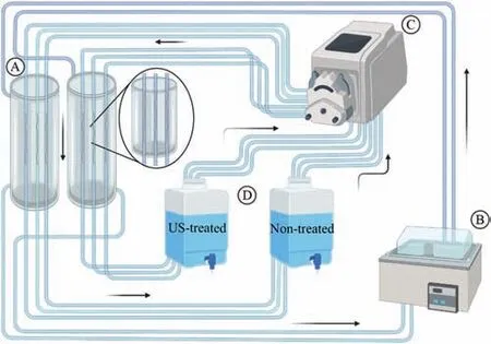
Fig. 1. Dynamic immersion test apparatus: (A) acrylic columns containing water at 37°C, (B) water bath, (C) peristaltic pump, and (D) EBSS reservoir.
2.3. Characterization of the samples
Scanning electron microscopy with energy dispersive spectroscopy (SEM-EDS JSM-6010LV with INCAx-act,PentaFET Precision, Oxford Instruments) was used to examine the surface morphology and composition of the corroded wires before and after corrosion products removal. To complement the weight loss measurements,the rate of magnesium ions release from the material was evaluated, according to the best practices suggested in the literature [36]. The amount of cations release from the the non- and US-treated samples to the EBSS was measured by analyzing the collected EBSS aliquots through inductively coupled plasma - optical emission spectroscopy (ICP-OES) analysis (JY 2000 2, HORIBA JOBIN YVON). The EBSS samples collected were filtered with a 0.22 μm filter, diluted in a 1:10 ratio with deionized water. A mixture of 90% nitric acid solution – 5% nitric acid (69%) in deionized water - and 10% EBSS was prepared before the ICP analysis. Surface chemical analysis was performed using X-ray photoelectron spectroscopy(XPS)(Shimadzu Kratos Supra Axis) with a monochromatic Al KαX-ray (1486.6 eV) operating with an X-ray source of 225 W.Samples were analyzed under vacuum with a pass energy of 160.0 eV in the survey scans and 20.0 eV for high-resolution scans. All spectrum peaks were measured relative to the peak binding energy of the C 1s peaks of carbon atoms of the hydrocarbon segments (285.0 eV).
The corrosion products were removed by soaking the wires for 15 min in chromic acid (200 g/L) at room temperature.The samples were sequentially cleaned with deionized water and ethanol. The weight lossΔm(mg) was determined using the difference between the original and final mass of the wires after washing using the following equation to obtain the corrosion rateCR(mm/year) [37]:
whereAis the surface area of the samples (cm2), andtis the immersion time (days).
Tensile tests of the as-extruded wires before and after degradation were performed using universal testing equipment (H100KS Hounsfield Universal Testing Instrument) at a constant cross-head speed of 1 mm/s. The ultimate tensile strength and elongation were calculated by averaging the results of ten separate tests.
3. Results and discussion
3.1. Characterization of the material’s microstructure before the immersion test
Fig. 2 shows the microstructures obtained through optical and scanning electron microscopy of the non- and US-treated alloys in the as-cast and as-extruded conditions.
The microstructures were composed ofα-Mg, eutecticβ-Mg17Al12, and a minor fraction of Al-Mn-rich phases in both conditions. Calcium added to the alloy was dissolved in theβ-Mg17Al12owing to its low solubility in the matrix and insufficient content to establish a new phase[38],as reported by Nam et al. [39]. Ultrasound melt treatment promoted the microstructure refinement(Fig.2(c)),leading to the formation of finer intermetallic dispersed uniformly along the grain boundaries and replacing the eutecticβ-Mg17Al12massive lumps by short and thin networks [40]. Ultrasound refinement ability lies on a combination of mechanisms: cavitation-enhanced nucleation [41,42], improvement of the wettability of particles and increase in the active nucleus [40,43], and ultrasonic streaming that homogenizes the solute distribution [44], promoting uniform precipitation of the fine intermetallics. Otherwise, the solute would segregate and form coarse particles[45].
The microstructures of non- and US-treated samples became more alike in the as-extruded state due to the severe plastic deformation during extrusion at high-temperature. We observed a typical banded structure with refinedα-Mg grains andβ-Mg17Al12phase broken into smaller particles stretched into strips and scattered along the extrusion direction, forming the characteristic clustering of precipitates[46].Following extrusion, the intermetallics observed in the US-treated sample were smaller than those in the non-treated one; however,the differences were more notorious in the as-cast condition:bothβ-Mg17Al12and Al-Mn rich phases appeared to be finer,rounder,and more uniformly distributed in the US-treated material.
3.2. Corrosion tests
Fig. 3(a) depicts the corrosion rate of non- and US-treated wires in EBSS based on weight loss.
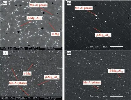
Fig. 2. Microstructure of the (a,b) non- and (c,d) US-treated samples in the as-cast (a,c) and as-extruded (b,d) condition (SEM).
The corrosion rate of the US-treated samples was higher for immersion up to 6 hours. This trend reversed over longer immersion, and the corrosion rate of the US-treated samples steadily reduced, showing enhanced corrosion resistance- after 7 days, the corrosion rate of the US-treated material was near half the non-treated one (1.43 vs 0.81 mm/year).Differences in the microstructure of the samples may explain the distinct corrosion behavior once the homogeneity and morphology of secondary phases are pivotal factors for the corrosion phenomenon [47,48]. Particularly, the size and distribution of the intermetallic phases, such as theβ-Mg17Al12phase, determine whether its presence improves or deteriorates the corrosion resistance of the alloy [49].This observation emphasizes the potential of ultrasound treatment to change materials’ corrosion behavior by modifying their microstructure [4]. Applying the ultrasound treatment to the AZ91D-1%Ca (wt.%) melt refined the as-extruded microstructure, homogenized the chemical composition, and formed smaller and spherical intermetallics particles evenly distributed throughout the matrix. The differences in the reaction to the corrosion medium exposure found between the materials lead us to believe that microstructural characteristics correlate with corrosion behavior.
After immersion for 6 hours, localized clusters of white particles were found on the non-treated sample’s surface(Fig. 3(a1)), while identical particles were evenly distributed on the US-treated one (Fig. 3(a2)), where deeper cracks suggested a thicker corrosion layer.
These findings agree with the increased corrosion rate reported at this immersion stage (Fig. 3(a)) since a quicker deterioration rate should result in more corrosion products on the exposed surface. Extending the immersion period beyond 6 hours shifted the corrosion behavior of the samples. Under these conditions, the US-treated sample exhibited the lowest corrosion rates, translating into a difference in the corrosion products and marks. Indeed, higher magnesium ion concentration (Fig. 3(b)) in the circulating solution of UStreated samples confirms increased degradation once the material’s substrate dissolution is the magnesium ion’s source.We also observed a sharp decrease in the ion’s concentration in the US-treated condition after 24 hours, which is compatible with the formation of corrosion products on the wires’surface, preventing further corrosion attack and thus reducing the corrosion rate.However, the magnesium ion concentration rises again before stabilizing, suggesting that the first corrosion layer may have dissolved before an outer non-soluble layer formed. The evolution of the calcium ion concentration(not shown) agrees with this hypothesis as its value drops severely after 2 days, indicating the formation of non-soluble calcium-containing salts. Conversely, the magnesium ion concentration is lower for the non-treated samples,increasing and decreasing successively during the immersion test, thus, suggesting a sequence of formation and dissolution of the corrosion product layer.Additionally,the calcium ion concentration decrease is much less expressive, which may indicate that the non-soluble protective corrosion layer’s formation occurs to a smaller extent.
Figs.4 and 5 display the corrosion morphology of the nonand US-treated wires after immersion for 3 days before and after corrosion products removal. On the non-treated sample,white agglomerates were stacked on the corrosion products(Fig. 5(a)). Mud cracking of the corrosion layer suggests low film integrity, limiting the protection against additional corrosion once the cracks expose the substrate to the corrosive solution and accelerate its attack.
After removing the corrosion products, the corrosion sites were distributed along the extrusion direction, and microgalvanic corrosion signs with a few corrosion pits were revealed (Fig. 4(d)) [50]. Corrosion marks dispersion in bands along the extrusion streamlines corresponded to the intermetallics distribution, suggesting an association between them.
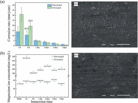
Fig. 3. (a) Corrosion rate and surface morphology of the non- (a1) and US-treated (a2) wires after immersion for 6 h in EBSS and (b) evolution of the magnesium ion concentration in the circulating solution during the immersion tests.
In the US-treated sample (Fig. 5), small agglomerates of white compounds with a cobweb-like structure were deposited on the surface, as described by Song et al. [51]. Few powderlike corrosion products (Fig. 5(a)) covered the surface, and only a small area exhibited mud cracking. After cleaning, the wire’s surface showed an evenly distributed mix of microgalvanic and smooth pitting corrosion marks (Fig. 5(c) and(d)). No evidence of extensive localized corrosion was noticeable.
EDS analysis (Fig. 4(b) and Fig. 5(b)) of the corrosion products identified magnesium, oxygen, calcium, and phosphorus, corresponding to the precipitation of MgxCay(PO4)zwhite compounds and Mg(OH)2mud layer. Additionally,the presence of carbon and sodium suggests the precipitation of Na4Mg(PO4)2, Mg(PO4)OH), and MgCO3[52,53].
After immersion for 7 days (Fig. 6 and 7), the corrosion morphology differences between non- and US-treated wires became more pronounced. The corrosion products of the nontreated sample had a more regular shape (Fig. 6(a)), with a few clusters covered with a P- and Ca-rich white material stacked on the substrate (Fig. 6(b)). The absence of mud cracking indicates enhanced integrity, favoring the decrease in the corrosion rate (Fig. 3(a)). However, cobweb-shaped agglomerates breached in the center and flaked away, exposing the substrate. The corrosion product removal revealed a severely deteriorated surface (Fig. 6(c)) with several localized and micro-galvanic corrosion marks (Fig. 6(d)).
Snowflake-shaped corrosion products protruding from the surface covered the US-treated wire, indicating a thicker corrosion layer compared with the non-treated sample (Fig. 7(a)and (b)).
A P-and Ca-rich substance covered most corrosion product clusters, as observed for non-treated samples; however, a uniform layer with few visible cracks formed in the US-treated wires’surface after exposure for 3 and 7 days.Conversely,the surface morphology of non-treated samples showed a cracked film with several localized aggregates of corrosion products.The US-treated wire surface displayed localized corrosion after the removal of the corrosion products, comparable to the non-treated sample (Fig. 7(c) and (d)), although in a much smaller region. Circular and deeper corrosion pits were observed.

Fig. 4. Surface morphology of the non-treated samples (a,b) before and (c,d) after removing corrosion products – 3 days immersion.
Observing the cross-sectional morphologies of the degraded samples and the EDS mapping can provide critical insights for understanding the corrosion phenomena,as shown in Figs.8 and 9 for non-and US-treated samples after immersion for 7 days, respectively. As Mei et al. [54] observed in their work, preparing the samples for analysis promoted the crack of the corrosion product layers and, thereby, their delamination, visible in the images obtained. The SEM images show that the morphology of the corrosion layers is obviously distinct between the processing conditions. The thickness of the corrosion product film is severely irregular in the non-treated sample (Fig. 8(a) and (b)), while the US-treated one shows a thicker and uniform layer along the whole surface (Fig. 9(a) and (b)). Also, the non-treated sample exhibits some localized areas of severe corrosion spreading inwards the wire (Fig. 8(b)), which can seriously compromise the material’s mechanical integrity. EDS mapping results (Fig. 8(c)and 9 (c)) show that this area is rich in oxygen and magnesium, suggesting the formation of MgO and/or Mg(OH)2,which are incapable of protecting the material from further degradation. Ca- and P-rich products cover the O-enriched compounds that form near the material’s surface in both samples, with the US-treated one showing a clearly thicker layer of these non-soluble compounds. These results are consistent with the abovementioned hypothesis that US-treated samples corrode faster at the initial immersion periods, forming a higher quantity of corrosion products that act as barriers and prevent corrosion.
We hypothesize that the shape and dispersion of intermetallic phases in the extruded condition cause the observed variations in the corrosion mark patterns between the non- and US-treated samples. Al-Mn andβ-Mg17Al12phases have noble potentials relative to theα-Mg matrix and may act as cathodes and induce micro-galvanic corrosion, diminishing the alloy’s overall performance [55,56]. Although some authors [57–60] have considered that a continuous network of secondary phases may act as a barrier to the propagation of corrosion, the intermetallics were disrupted and transformed during the extrusion process,hindering the formation of a web around theα-Mg grains. In both conditions, the intermetallic particles behaved as the cathodic phase and favored the breakdown of the matrix. The deep and large concavities in the non-treated samples were consistent with the coarser and non-uniform distribution of the intermetallic phases throughout the matrix. The finer and uniformly distributed secondary phase found in US-treated samples resulted in smaller, more evenly distributed corrosion signs.
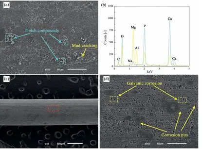
Fig. 5. Surface morphology of the US-treated samples (a,b) before and (c,d) after removing corrosion products – 3 days immersion.
XPS-wide survey scans (Fig. 10) confirmed magnesium,aluminum, carbon, oxygen, calcium, and phosphorus presence in both samples; therefore, high-resolution narrow survey scans (Fig. 11 (a)-(j)) were performed for these elements.Magnesium and aluminum peaks came from the substrate of the wires, whereas calcium and phosphorus formed the corrosion products deposited. The deconvolution of the XPS spectra for the Mg 2s, C 1s, O 1s, Ca 2p, and P 2p peaks are shown in Fig. 11. The Mg 2s spectra (Fig. 11(a) and (b)) are fitted to three components: one peak at 87.0 eV, which corresponds to the presence of MgO, and two peaks at 89.0 eV and 89.5 eV, which correspond to the Mg(OH)2and MgCO3compounds, respectively [61]. The peaks at 285.0 eV and 289.0 eV in C 1s spectra (11 (c) and (d)) indicate the existence of C-C/C-H groups, Mg-CO3, and Ca-CO3compounds.The peaks in the O 1s spectra (11 (e) and (f)) correspond to the binding energy from the PO43-, OH-,and CO32-groups,as well as to oxygen present in the MgO compound [62,63].Each recognized peak in the Ca 2p spectra (Fig. 11(g) and(h))exhibits the doublet band typical of calcium-oxygen compounds [47]. Due to spin-orbit splitting, the spectrum breaks into two peaks of Ca 2p3/2 and Ca 2p1/2, further demonstrating the presence of Ca10(PO4)6(OH)2[46]. The peak at 347.8 eV is related to the Ca-O binding energy and hence indicates the existence of the CaO compound, while the peak at around 347.0 eV suggests Ca-CO3presence [47]. In the P 2p spectra(Fig.11(i)and(j)),two peaks positioned between 133.0 eV to 135.0 eV are found, suggesting the presence of Mg-PO4and Ca-PO4compounds, which agrees with the high-resolution spectra of Mg 2p and Ca 2p [64,65].
The corrosion products formed are identical for both nonand US-treated samples; however, US-treated samples exhibited higher quantities of all the identified compounds at the surface, which supports that these samples corroded at a higher rate during the initial immersion stages.
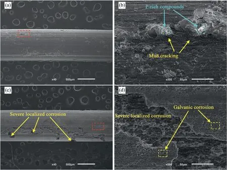
Fig. 6. Surface morphology of the non-treated samples (a,b) before and (c,d) after removal of corrosion products – 7 days immersion.
We suggest that the degradation behavior of the US-treated material has two stages. At first immersion hours, the UStreated wire corrodes more severely due to the distribution of small intermetallics that act as cathodes, forming larger quantities of corrosion products [10]. Afterwards, the uniform corrosion layer protects the substrate and slows corrosion rates.These observations agree with Jiang et al. [66], who studied the effect of the CaCO3layer on the corrosion resistance of an Mg-Zn-Ca alloy. Furthermore, the intermetallics morphology eased the formation of corrosion pits whose growth led to the detachment of small particles, hindering the propagation of the corrosion and generating a smoother layer. Although the corrosion process was comparable in the non-treated samples,the intermetallics were coarser and formed agglomerates,resulting in severe micro-galvanic corrosion in isolated locations. The localized corrosion quickly spread throughout the material along the coarse intermetallic phase, as stated by Yin et al. [48]. The hypothesis presented is supported by the findings of Choi et al. [67], who documented the overlap between the morphology of the intermetallics and the corrosion marks in AZ91. The refined microstructure - especially the small intermetallic particles and the uniform distribution of aluminum-granted by the ultrasound treatment can be associated with a uniform and compact oxide film, leading to higher corrosion resistance. Also, the low surface area ratio of the cathode to anode is not enough to promote severe localized corrosion to a great extent [47].
The composition of the corrosion products affects corrosion resistance and degrading behavior: if the compounds formed are poorly soluble, their degradation will be slowed down, and the corrosion products will coat the substrate. The surface conditions influence the corrosion products that can precipitate and, hence, the corrosion protection granted by them. Fig. 12 shows a model for the corrosion reactions between the magnesium substrate and the EBSS.
The magnesium substrate is corroded when exposed to aqueous media such as physiological fluids. According to Song et al. [51], Mg(OH)2forms during the first stages of immersion, mainly in the grain boundaries, as the result of the reduction of the water and the oxidation of magnesium,as follows:
The dissolution and strength of the Mg(OH)2layer depend deeply on the other chemical species present in the corrosive medium and the immersion time[68].When exposed to EBSS and as the immersion proceeds, the Mg(OH)2is partially dissolved through the reaction with Cl-anions present in the electrolyte:
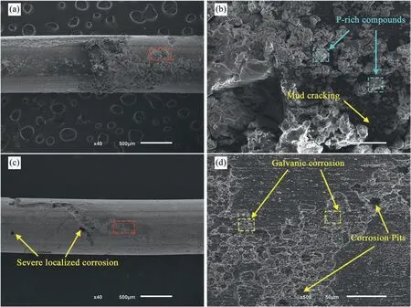
Fig. 7. Surface morphology of the US-treated samples (a,b) before and (c,d) after removal of corrosion products – 7 days immersion.
Such a reaction increases the local pH, favoring the decomposition of the HPO42-species into PO42-and H2O as described by equation 4.7:
The phosphates released bond preferentially with Ca2+and Mg2+cations, forming white precipitates identified as MgxCay(PO4)zon the surface, which adhere to Mg(OH)2layer. These corrosion products are not water soluble, providing additional protection.
Additionally, according to Eq. 10, the MgCO3compound can be formed through a reaction between the atmospheric CO2or NaHCO3present in the electrolyte and the Mg2+cations released from the substrate [69,70]:
The faster corrosion rate of US-treated samples during the first stages of the immersion tests led to a thicker Mg(OH)2film with plenty of phosphorus- and calcium-rich white particles. Hence, higher corrosion resistance was achieved, resulting in a sharp decrease in the corrosion rate after 6 hours.
3.3. Mechanical characterization
Fig. 13 shows the evolution of the ultimate tensile strength(Fig. 13(a)) and elongation (Fig. 13(b)) of the non- and UStreated wires with the immersion time. Before immersion, the non-treated material had the maximum tensile strength (354 MPa vs. 347 MPa); however, the US-treated significantly exceeded it in elongation at break (16.7% vs. 20.7%). After immersion in EBSS,both mechanical characteristics deteriorated gradually regardless of the material processing once mass loss at the interface compromised the wires’integrity[71]. After 7 days,the tensile strength of the non-treated material decreased by 28.6% and elongation at break by 86.3%. Similarly, UStreated wires’ tensile strength and elongation decreased by 15.4% and 83.6%, respectively. Despite the comparable elongation values, the US-treated sample showed a 15.2% higher final tensile strength. The tensile strength of the non-treated wires remained higher than those of US-treated ones during the first immersion stages, which agrees with the lower results obtained for the corrosion rate. From 1 day on, both tensile strength and elongation remained almost constant for the US-treated sample. This behavior agrees with the gradually decreasing corrosion rate, suggesting a stabilization of the materials’ deterioration. Yet, despite the US-treated samples’ corrosion rate being lower than the non-treated ones from immersion for 1 day on, the tensile strength behavior shift occurred only after 3 days. These results suggest that the mechanical properties change may mismatch the corrosion rate trend, which agrees with previously published work[54].

Fig. 8. SEM images of the non-treated sample’s cross-section (a) wire view and (b) localized corrosion site ampliation. (c) EDS mapping of C, Mg, O, P and Ca elements – 7 days immersion.
We found that the differences observed in the degradation process of the non- and US-treated materials were reflected in their mechanical response, and the exposure to EBSS lowered their mechanical properties. The tensile strength of the UStreated samples considerably exceeded the non-treated ones after immersion for 3 days in EBSS, a tendency also noticed after 7 days. The transmission of the corrosion attack via the coarse intermetallics within the non-treated material may have weakened it, accelerating its fracture. Furthermore, the material loss from the surface encourages its roughening owing to the creation of depressions and produces local stress, a phenomenon observed by Linderov et al. [72] and clearly shown in Fig. 8. On the other hand, the presence of localized corrosion sites promotes the formation of microcracks and thus stress concentration. All these phenomena can contribute to the early fracture of wires and reduced tensile strength.
Magnesium alloys are prone to brittle failure, commonly in the form of cleavage or quasi-cleavage fracture, promoted by the limited slip system [73]. However, Li et al. [74] have previously described a shift to ductile fracture during hot extrusion due to grain refinement induced by strong plastic deformation.
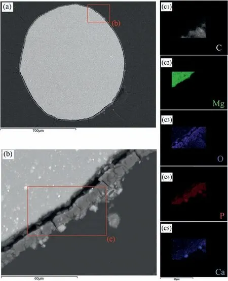
Fig. 9. SEM images of the non-treated sample’s cross-section (a) wire view and (b) localized corrosion site ampliation. (c) EDS mapping of C, Mg, O, P and Ca elements – 7 days immersion.

Fig. 10. XPS-wide survey scans for non US-treated samples after immersion in EBSS for 7 days.
The fracture behavior of the non- and US-treated specimens before and after immersion in EBSS for 7 days was investigated (Fig. 14). Before the immersion tests, non- and US-treated fracture surfaces showed a combination of a few rough cleavage faces and plastic deformation zones with several dimples (Fig. 14(a) and (b)). We observed secondary phases and oxides,which might serve as fracture starting sites.Zhou et al. [75] observed a similar fracture surface pattern comparable with a conventional brittle-ductile failure mechanism. While both samples exhibited comparable fractographic characteristics,Fig.11 suggests that US-treated wire had more dimples and fewer cleavage planes, consistent with its higher elongation at break in the non-degraded state. Following the findings reported by Sozánska et al.[46],non-and US-treated samples immersed in EBSS for 7 days appeared to gradually exhibit more cleavage facets and cracks, indicating that intergranular fracture occurred (Fig. 14(b) and (d)).

Fig. 11. High-resolution XPS spectra for non- and US-treated samples after immersion in EBSS for 7 days.

Fig. 12. Proposed mechanism for the AZ91D-1%Ca (wt.%) reactions and corrosion product formation in EBSS.

Fig. 13. Mechanical properties of the non- and US-treated wires: (a) ultimate tensile strength, (b) elongation at break.

Fig. 14. Fractography of the (a,b) non-treated and (c,d) US-treated samples, (a,d) before immersion and after immersion for 7 days.
Our results show that ultrasound treatment can modify the material’s corrosion response, but we must disclose that this study still has limitations.The corrosion resistance granted by ultrasound treatment was inefficient in meeting the maximum corrosion rate of 0.5 mm/year, which is mandatory for coronary stent manufacturing [47] – our best value reached 0.8 mm/year. We suggest further research to optimize the material processing (e.g.,ultrasound working parameters) to slow the corrosion rate and extended immersion tests to assess the material’s behavior under longer exposure to the corrosive medium as a stent undergoes. Also, we believe that exploring the potential to transpose this processing route to other alloys suitable for biomedical applications such as AZ31 deserves attention.
4. Conclusion
This study investigated whether ultrasound melt treatment influences the as-extruded microstructure and, thereby, the corrosion behavior of an AZ91D-1%Ca (wt.%) magnesium alloy in EBSS.
The main findings of this work allowed concluding:
1. Ultrasound treatment led to the refinement of the as-cast and as-extruded microstructures of the AZ91D-1%Ca(wt.%). The most evident effect was the decrease ofβ-Mg17Al12and Al8Mn5particles’ size and homogeneous distribution throughout the matrix after extrusion.
2. The corrosion rate and the degradation product morphology of the non- and US-treated materials subjected to an EBSS flow differed. We hypothesize that microstructural characteristics, mainly the intermetallics size and distribution, underlie this behavior.
3. The corrosion rate for US-treated samples was higher during the first hours (up to 6 hours), with a shift in this tendency for longer immersion periods. Small and evenly distributed intermetallic particles in the UStreated samples may have promoted an accelerated degradation of the material in this initial phase. A corrosion layer covered the wire’s surface, delaying further corrosion attacks and reducing the corrosion rate. Also,we observed a more uniform degradation with fewer severe localized corrosion signs.
4. The non-treated samples displayed marks of severe localized corrosion, which correlates with the coarse morphology of the intermetallics, confirming the preferential corrosion attack in these regions.
5. The analysis of the cross-section of the non- and UStreated samples after immersion for 7 days confirm that the latter corroded more uniformly, being visible a thicker corrosion layer while in the former severe marks of localized corrosion were visible spreading into the material core.
6. The deterioration of the mechanical properties occurred regardless of the processing conditions. Higher tensile strength characterized the US-treated material after the immersion tests, while the elongation values were comparable. Fractography revealed that intergranular fracture occurred after immersion in EBSS for 7 days, suggesting that intermetallic particles served as fracture starting sites.
7. We found that ultrasound melt treatment modifies the as-cast and as-extruded microstructure of the material,revealing an excellent potential for the fabrication of biodegradable stents by tuning their microstructural and,thereby, corrosion properties.
Declaration of competing interest
The authors declare that they have no known competing financial interests or personal relationships that could have appeared to influence the work reported in this paper.
Acknowledgements
This work was supported by Portuguese FCT under the project UIDB/04436/2020, the doctoral grant PD/BD/140094/2018 and SFRH/BD/145285/2019.
杂志排行
Journal of Magnesium and Alloys的其它文章
- NaH doped TiO2 as a high-performance catalyst for Mg/MgH2 cycling stability and room temperature absorption
- Microstructure, mechanical properties and fracture behaviors of large-scale sand-cast Mg-3Y-2Gd-1Nd-0.4Zr alloy
- Enhanced initial biodegradation resistance of the biomedical Mg-Cu alloy by surface nanomodification
- Elucidating the evolution of long-period stacking ordered phase and its effect on deformation behavior in the as-cast Mg-6Gd-1Zn-0.6Zr alloy
- Effect of long-period stacking ordered structure on very high cycle fatigue properties of Mg-Gd-Y-Zn-Zr alloys
- The mechanism for tuning the corrosion resistance and pore density of plasma electrolytic oxidation (PEO) coatings on Mg alloy with fluoride addition
