Robust design and analysis for opto-mechanical two array laser warning system
2023-10-09MzhrTyelMohmedShehtMohmedMroukAdlrhmnAdelMohmedShdyShokryMostfAlshershy
Mzhr Tyel ,Mohmed Sheht ,Mohmed Mrouk ,Adlrhmn Adel Mohmed ,Shdy Shokry ,Mostf Alshershy ,*
a Faculty of Engineering,Alexandria University,Alexandria,Egypt
b Egyptian Air Defense Collage,Alexandria,Egypt
c Laser and Optoelectronics Department,Technical Research Center,Egypt
Keywords:LWS Field of view Detector elements
ABSTRACT In the past three decades,laser warning systems (LWS) have emerged in great importance,as the development of laser-guided weapons,such as airborne Hellfire missiles,has increased,posing an imminent threat to vital areas and VIPs.The laser warning station(LWS)can detect,classify,identify,and give alarm from laser threat at a very short time with high sensitivity.Therefore,the designers of this system must take into account the detectability and field of view to cover the area to be secured.The main contribution in this research is an analytical design of LWS that consists of 24 detector elements,distributed in two arrays (2 × 12) circularly.Also,calculating the best distance between the detectors according to the laser beam spot size.In addition,enhancement laser warring sensor detection capability and detection performance FOV between the detectors to increase coverage area up to 360°.Moreover,decreasing dead zone area between the laser detectors element.Mathematical calculations and illustrations made to reach the best systematic design.
1.Introduction
A laser warning system (LWS) is a set of photo detectors (PDs)structured and arranged in a certain manner to detect,identify and provide warning against laser threats.A LWS can operate as a laser range finder (LRF),laser target designator (LTD),laser beam riding(LBR)missile,and as laser blinder weapons[1,2].Also,a LWS can be used to activate a counter measurement systems that is available on a platform directly via an intelligent system[3].
The most important factors effecting detection in a LWS are:low level false alarm rate,high speed processing,high reliability,high probability of detection,wide dynamic range,and large optical coverage both in azimuth and elevation [3].
Laser Beam spot(LBS)detection,in a LWS,is provided by using a set of photoelectric effect diodes built in different structures and arranged with different configurations.These devices are structured in solid-state semiconductor material compounds or alloys that are characterized by their unique features,e.g.very small size,light weight,low power consumption,low noise,and high packing density.These features make LWS a compact system[4,5].
There are a different configuration for LWS studied such as composed of an antenna based on fiber bundle and a Michelson interferometer[6],Spectral Discrimination and Coherent Detection[7,8].This paper aims to analyze and design a LWS with a predetermined azimuth and elevation coverage area and with a predefined field of view(FOV).In addition,the paper deals with precise determination of laser detectors best construction.The system persistence aim to characterize the hostile optical signals [9-19]from a widespread distance of incident angles.The electronic counter measurement system(ECMS)is activated by laser warning station automatically [9-12].
2.Construction of photo detectors (PDs) in a LWS
A LWS is consists of an array of photo detectors (PDs) set arranged in a certain manner to obtain highest detection probability of LBS of smallest size.The PDs set have many construction configuration depending on application [2,6,20,21].
There are three common constructions available in applications,namely: single segment detector (SSD),double segment detector(DSD) and quadrant segment detector (QSD) [22-24] as shown in Fig.1.
To obtain higher resolution the configuration of the QSD is to be used.A proposed LWS consists of an array of these QSD to detect the location of the LBS.Fig.2 illustrates the construction of two identical successive QSD numerated asDNandDN+1of equal diameters and are separated by a gap of distance (g).
From Fig.2(a),it is seen that a LBS with diameterds
3.Induced current in a spot scanned QSD
Fig.3 demonstrates scanning of a QSD by LBS from left to right withdd=2ds.Table 1 gives the amount of induced current of each segment during LBS scanning.The angular resolution of an optical lens is chosen to be from 0.5 to 3rd.A LWS should have a circumference depend on the distance between the QSD elements,considering two points of view namely the FOV,and the LBS localization.
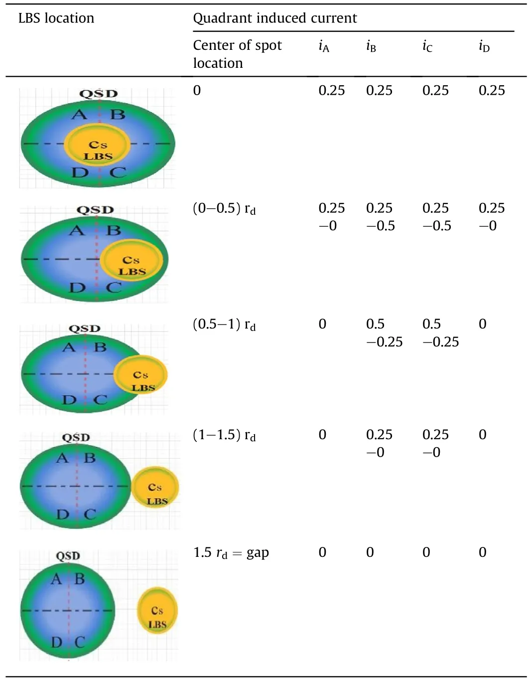
Table 1 The Induced current in QSD segment.
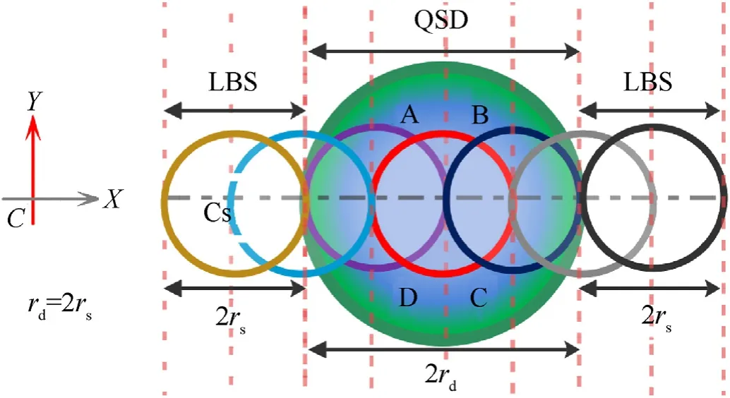
Fig.3.A Beam spot scans a QSD.
4.Design of LBS optics
The following presents the construction of FOV that produced between a two successive QSDs to predict existence of a laser threat.Fig.4 shows the principle of optical system to construct a FOV,whereas successive QSDs are to be used.in Figs.5 and 6 gives the optical subsystem design (OSD) after ray tracing by a special software design.It contains a four lens to achieve the maximum gathering ray.The technical specification of lenses shown in Table 2.
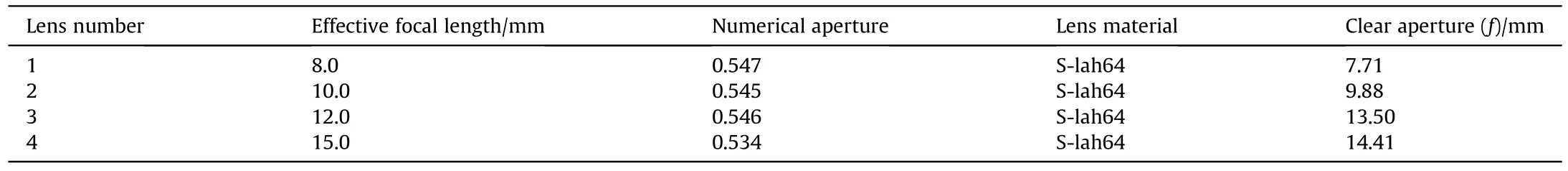
Table 2 The technical specification of lenses.

Fig.4.The optical system FOV.
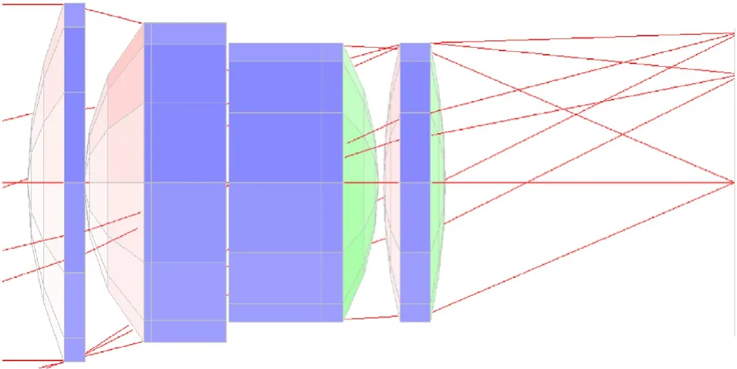
Fig.5.The optical subsystem design after ray tracing.
Fig.6.The optical system for one detection channel.
where,ℎ′is half of the entrance pupil diameter,and σnis half of FOV,and f is the focal point of a proposed optical lens.
Thus the FOV Depends on incident angle,and energy received by QDS,The incident angle of the LBS can be worked out depending on the amount of laser energy received on different QSDs [26-29].Considering Figs.4-6 and 7,the proposed design parameters are calculated and are presented in Table 3.
Table 3 The proposed design parameters calculated.
5.FOV calculation
5.1.Field of view overlapping and dead zone calculations
The FOV,optical axis distribution and relationship of two successive QSDs are shown in Fig.7 all calculation made by using Solid Work Program.Where,Dis represents the detector element,nis represents detector number,σ’ is the field of view angle,rdis the distance from a QSD to edge of overlapping,θ is the overlap angle between the two adjacent QSDs all value of these parameters indicates in Table 3.
Fig.7.The detector heads FOV overlapping.
Fig.8 shows the FOV and optical axis distribution of three successive QSDs (DN-1,Dn,Dn+1).The FOV for every QSD,The overlapping angle between detection elements,the overlapping distance from warning unit chasing,and dead zone area are indicated in the same figure.Fig.9 shows the 3D optical FOV and optical axis distribution of the QSDs (DN-1,Dn,Dn+1).
Fig.8.The FOV overlapping of three successive QSDs.
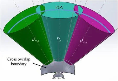
Fig.9.The FOV overlapping of three successive QSDs in 3D.
5.2.The LBS location detection
For a LBS incident on one or more QSDs,a multiple receiving lens will arranged to obtain FOV overlapping so that the four quadrants can receive energy no matter in what angle the laser reaches.The operation principle shown in Fig.10.

Fig.10.The Schematic diagram of overlapped FOV for multiple QSDs.
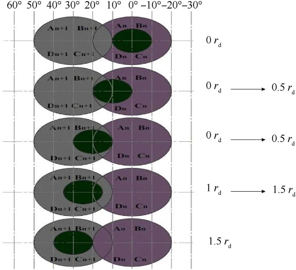
Fig.11.Energy codes different quadrants for different incident angles with two QSDs overlapped.
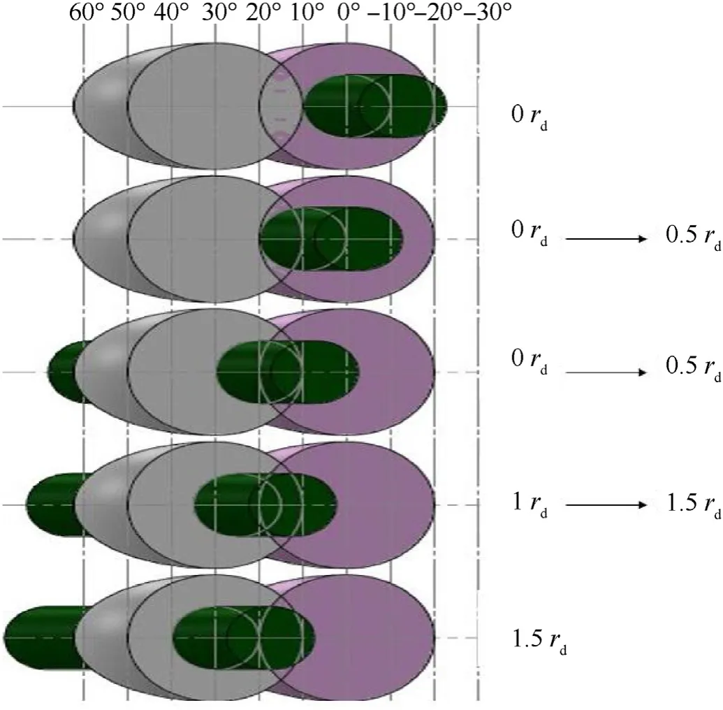
Fig.12.Energy codes different quadrants for different incident angles with two QSDs overlapped in 3D.
The amount of normalized energy (E) distribution on different quadrant QSDs from different incident angles shown in Table 4.

Table 4 Energy distribution on different quadrants(Q)for different incident angles with two QSDs overlapped.
Table 4 shows multiple two successive QSDs overlapped FOV where optical axis angle included between the adjacent detectors is 1.5th,judge,if there is energy received or not on each QSD to determine the incident angle and make the angular resolution be up to 0.5rd.Figs.11 and 12 show different quadrants energy codes for different incident angles with the two QSDs overlapped in 2D and 3D dimension.
5.3.Enhancement of FOV
A proposed design is introduced to enhancement the FOV by constructing two layers LWS of QSDs 2 × 12 arranged in two circular shapes raw arrays with diameter 80 cm with equal spaced angles 30°from the center of circular shape.In order to increase the coverage and detection area as shown in Fig.13.
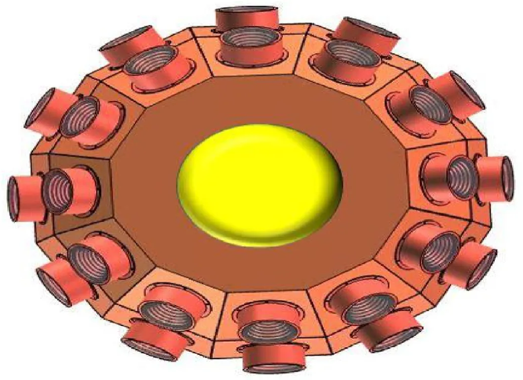
Fig.13.The layout of the two QSDs raw arrays of laser warning head.
Fig.14 shows overlay between the upper and the lower raw head arrays of LWS.To illustrate detection resolution in different direction,assume an incident LBS located between four QSDs,two of them are in the upper array and other QSDs are in the lower array.Table 5 shows the four detectors overlapped FOV codes in a horizontal axis where the optical axis angle included between adjacent QSDs to be within 1.5rd.Overlapped FOV codes in vertical axis are calculated by the same method as that used in horizontal axis.
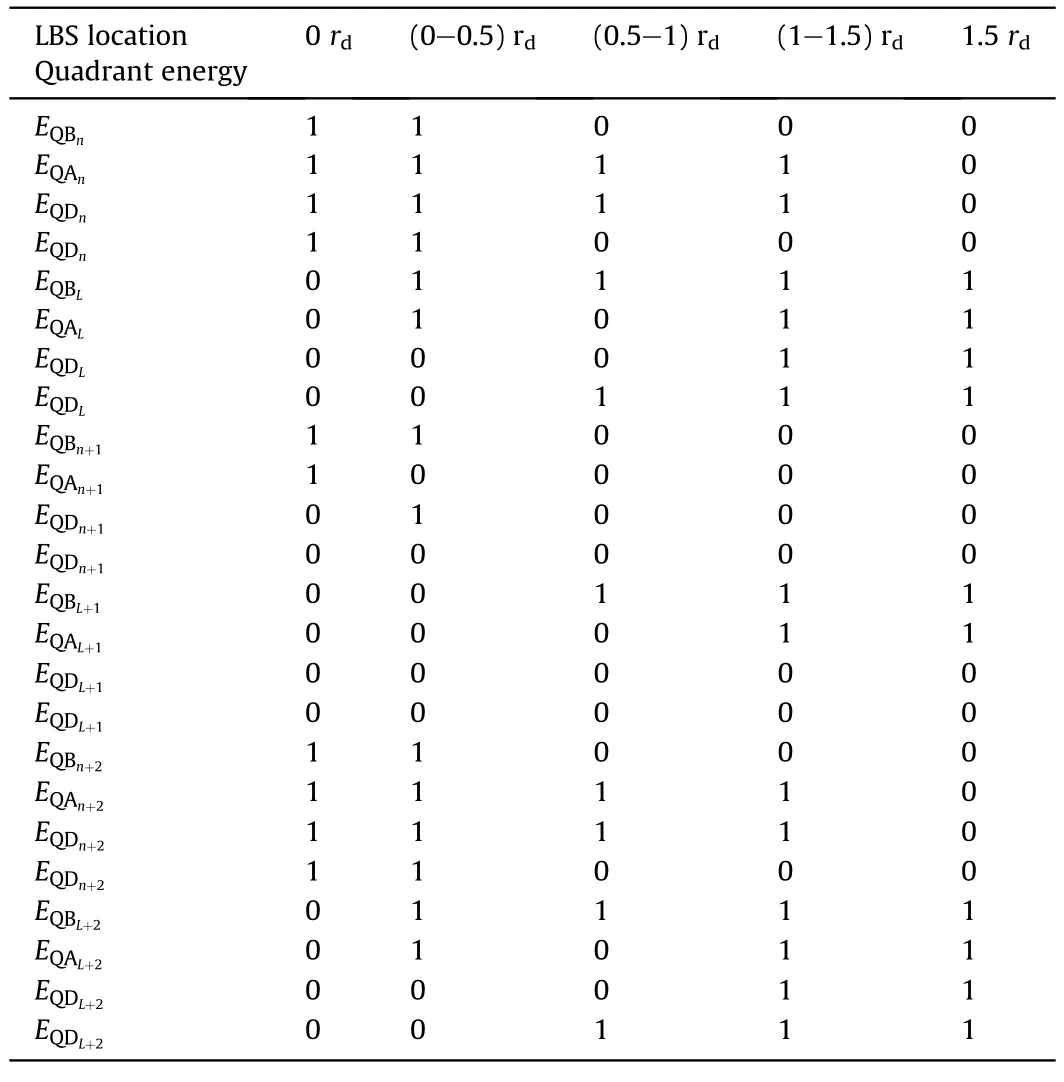
Table 5 The Four quadrants energy codes for different incident angles with multiple QSDs overlapped in horizontal direction.
Fig.15 shows the 3D overlapped FOV between the upper and the lower arrays.
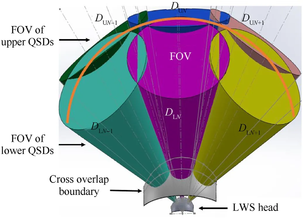
Fig.15.The Upper and The Lower arrays of QSDs overlapping in 3D.
For three detector elements,the LBS on theDN-1,NandDN+1detectors are distributed as in Fig.16 Energy distribution on the three QSDs (DN-1,DNandDN+1) from different incident angles is presented in Table 6,define1 for energy received on a quadrant while (0) for no energy received.
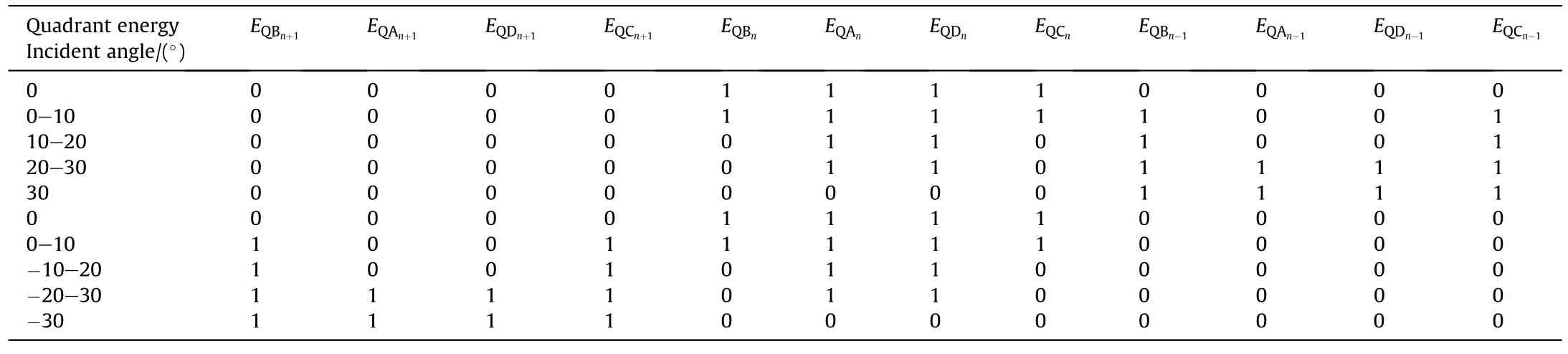
Table 6 Energy codes different quadrants for different incident angles with three QSDs overlapped.

Fig.16. DN and DN+1 DEs FOVs.
6.Conclusions
The optimal localization for 24 DEs,distributed in two arrays(2×12)in a circular shape for LWS based on SPSD Spot-13A-YAG-FL with field of view of 40°,which is commercially available,is to distribute them on circular shape with 360°coverage in azimuth.Showed from this design the maximum dead zone area is about 106.92 m in case of overlap field of view 10°for each detector element.To reduce the dead zone distance added a second raw of detectors to increase the FOV and the coverage area of the LWS.Based on configuration the dead zone will be half of one raw LWS,in addition the laser spot size will occupy the half of the detector's sensitive area,which meet the optimal requirement of the threat detection.Beam divergence of incident laser threat must be greater than of warning detection size in case LTD fired from aircraft or ground platform designators,and the overlapping FOV area between DEs occurs at 1.06 m from warning detection unit,so that there is no dead zone area for purposed design the probability of detection is more than 99.9%.
Declaration of competing interest
The authors declare that they have no known competing financial interests or personal relationships that could have appeared to influence the work reported in this paper.
杂志排行

Defence Technology的其它文章
- Cooperative maneuver decision making for multi-UAV air combat based on incomplete information dynamic game
- Satellite breakup behaviors and model under the hypervelocity impact and explosion: A review
- Recognition model and algorithm of projectiles by combining particle swarm optimization support vector and spatial-temporal constrain
- Time-sequenced damage behavior of reactive projectile impacting double-layer plates
- One-step rapid preparation of CL-20/TNT co-crystal assembly and spheroidized coating based on droplet microfluidic technology
- Mechanical properties and failure behavior of 3D printed thermoplastic composites using continuous basalt fiber under highvolume fraction