Mechanical properties and failure behavior of 3D printed thermoplastic composites using continuous basalt fiber under highvolume fraction
2023-10-09HangZhangWeifuSun
Hang Zhang ,Wei-fu Sun ,*
a State Key Laboratory of Explosion Science and Technology,Beijing Institute of Technology,Beijing,100081,China
b Beijing Institute of Technology Chongqing Innovation Center,Chongqing,401120,China
c Explosion Protection and Emergency Disposal Technology Engineering Research Center of the Ministry of Education,Beijing,10081,China
Keywords:Additive manufacturing Continuous basalt fiber Failure behavior Mechanical properties Thermoplastic composites
ABSTRACT Continuous basalt fiber (CBF) is an outstanding inorganic fiber produced from nature,which has a wide range of applications in the field of armor protection of national defense military.However,the mechanical response and failure mechanism of 3D printed CBF reinforced components are still not well understood.Here,the 3D printing thermoplastic composites with high volume fraction CBF have been successfully prepared by fused deposition modelling (FDM) method.The effects of fiber printing direction and polymer matrix type on the tensile and flexural properties of the 3D printed composites have been explored,and the detailed failure morphology has been characterized using scanning electron microscopy and optical microscopy.It was found that under high fiber volume fraction,3D printed CBF reinforced polyamides (PA) composites have the best ability to maintain material integrity of the composites,followed by acrylonitrile butadiene styrene (ABS) and high impact polystyrene (HIPS).Besides,the results from rule of mixtures can accurately predict the longitudinal Young’s modulus of the 3D printed specimens,but there exists a large discrepancy for the prediction of the tensile strength.The microstructure analysis shows that the failure modes of 3D printed composites mainly include fiber debonding,fiber pull-out,stress whitening and matrix cracking.
1.Introduction
Basalt fiber is made from natural volcanic basalt by smelting at 1500 ℃-1700 ℃ in furnace,then pulled into silk by platinumiridium alloy leaking plate [1].Basalt fiber has the following advantages such as low energy-consuming,non-flammability,high chemical stability,good weather resistance,alkali resistance,acid resistance [2-4],and it is cheaper than the other fibers such as glass and carbon fiber [5].The density of basalt fiber (2.63 g/cm3-2.8 g/cm3)is similar to that of glass fiber(2.54 g/cm3-2.57 g/cm3),but slightly higher than that of carbon fiber(1.78 g/cm3)[3].In addition,basalt fiber has higher tensile strength than glass fiber,larger failure strain than carbon fiber,and good anti-impact performance [4,6].As an alternative to glass,carbon and aramid fibers,basalt fiber has also received extensive attention in industry and academia in recent years [7-9].In particular,compared with other natural fibers(such as animals,plants or minerals)that can be used as reinforcement materials,basalt fiber-reinforced composites based on polymer (thermoplastic and thermosetting),metal and concrete matrix have exhibited good performance [5,8].These advantages make basalt fiber a promising military protective material[3,10-12].However,the effects of basalt fiber weave and lay-up modes on its mechanical properties are not systematically studied [4],especially the research on 3D printing CBF-reinforced composites is seldom touched upon.
Recently,continuous fiber reinforced thermoplastic composites(CFRTPCs)are becoming alternative materials to replace thermoset polymers and metals due to their excellent mechanical properties,reusability and potential lightweight structure[13,14].Much effort has been devoted to the internal and external morphological characteristics and mechanical properties of CFRTPCs fabricated by the FDM method [15-18],such as tensile and flexural properties,impact damage resistance,have been explored.Although basalt fiber holds great promise in engineering applications due to its superior performance [7-9],little attention has been paid to the mechanical properties of 3D printed CBF reinforced thermoplastic composites.Additionally,the service conditions and performance requirements of basalt fiber composites are different in practical applications [19-22].For example,composites used in the field of personal protection should be able to resist impact objects,requiring the back convex height and back damage area of the composite material to be as small as possible to avoid direct or indirect damage to the human body.However,from the perspective of energy absorption,the backside of the composites is allowed to have a larger convexity,so that more energy can be absorbed by forming a convexity on the backside,which is beneficial to improve the anti-impact performance[4].When the 3D printed component is impacted,the component is subjected to a certain degree of compression and bending load.Therefore,clarifying the mechanical properties and damage behavior of 3D printed CBF reinforced thermoplastic composites under bending load is an important basis for exploring the impact damage behavior of 3D printing CBF reinforced thermoplastic composites.Moreover,there is currently a lack of research on the layup sequence and laying angles of CBFs in the 3D printing process.Especially,it is necessary to systematically probe into the mechanical properties of 3D printed CBF reinforced thermoplastic composites under high volume fraction.
So far,additive manufacturing(AM)technology has been found to have potential applications for creating complex lightweight structures in the aerospace,electronics,and construction industries[23-26].This technology can accurately manufacture a wide range of prototypes or functional components with complex geometric shapes [27,28],such as the geometric configuration obtained from the topology optimization process or computer-aided design.Generally,the fabrication of the functional components can also be achieved through the process such as vacuum forming [29,30],filament winding [31,32],pultrusion [33],vesicle-assisted compression molding [34,35],etc.,but they normally require expensive facilities and equipment,which to a certain extent hinders the wide application of thermoplastic composites [13,18,36].Fused deposition modelling (FDM),as one of the commonly used AM technologies [37,38],has the advantage of low-cost and easy manipulation.Using FDM to fabricate CFRTPCs with much better performance has become a cutting-edge and cross-disciplinary research topic in recent years.Compared with prepreg composites,an important issue constraining the use of 3D printed CFRTPCs is the impact of the high fiber volume fraction.Due to the difference in fiber impregnation methods,fiber volume fraction of continuous fiber filaments has a wide span[15],which will inevitably affect the mechanical properties of 3D printed composites.Moreover,limited by the diameter of the fiber extruder of the 3D printer using the FDM method,higher fiber volume fraction of the filaments may lead to lower fiber infiltration degree.
In this work,we have successfully prepared the 3D printing thermoplastic composites by the fused deposition modelling(FDM)method with high volume fraction basalt fiber as the raw material.The commonly used typical thermoplastic polymers include polyamides(PA),acrylonitrile butadiene styrene(ABS)and high impact polystyrene (HIPS) were selected as the matrix during the 3D printing process due to their excellent physical and chemical properties [39-41].The influence of fiber layup sequence,fiber laying angles and matrix type on the final mechanical properties of CFRTPCs under high fiber volume fraction was studied and a comparison has been made with the semi-empirical method,i.e.,rule of mixture.The microstructure characteristics of the 3D printed CFRTPCs were comprehensively characterized by scanning electron microscopy (SEM) and optical microscopy (OM),and the damage behavior of the specimen under different loading methods was analyzed.This work provides an important experimental basis for the application of 3D printed CBF composites in the engineering field.
2.Experimental methods
2.1.Materials and 3D printer setup
All specimens used in this study were fabricated using a desktop 3D printer(Markforged®MarkTwo),which has two extruders and two printing heads to extrude and print plastic filaments and continuous fibers(Fig.1),respectively.In this work,the thickness of the printing layer was set to 0.125 mm,and the printing temperature of the thermoplastic matrix layer and the fiber layer were 273 ℃ and 232 ℃,respectively.The specific printing parameters are given in Table A1 of Appendix 2.PA,HIPS and ABS filaments are all provided by Zortrax® (Zortrax® M200),with a specific density of 1.027 g/cm3,1.136 g/cm3,and 1.195 g/cm3,respectively.And all the diameter of the thermoplastic filaments is 1.75 mm.High volume fraction continuous basalt fiber with an average diameter of 0.3 mm and a linear density of 400 tex is provided by Anisoprint®(Anisoprint®CBF).The geometry of the 3D printed specimens was modelled using SolidWorks software,exported as a stereolithography (STL) file and then imported into the 3D printing software.
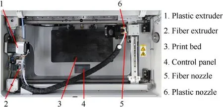
Fig.1.Top view and components of the Mark Two desktop 3D printer.
2.2.Mechanical testing
In this work,the tensile and flexural properties of 3D printed CBF reinforced composites were performed on a universal testing machine(MTS CMT-5105)with a loading cell of 5 kN and analyzed according to the ASTM D638-14 standard[42]and the ASTM D790-15[43]standard,respectively.The morphology and failure behavior of the specimens were characterized using scanning electron microscopy(SEM,Hitachi S-4800)and optical microscopy(OM,Leica-M4).The fiber printing direction of the tensile specimen is shown in Fig.2(a) and the total number of layers of the tensile specimen in the FDM process is 28,including 9 layers of fiber and 19 layers of matrix.An extensometer with a gauge length of 25 mm is used to measure the strain of the tensile specimen at a loading rate of 1 mm/min,and a specialized computer is used to collect the data of the load cell and the extensometer.Fig.2(b) shows fiber printing directions (fiber laying angle) of the bending specimen.The dimension,the span and the span-thickness ratio of specimen are 154×13×4 mm3,128 mm,and 32:1.The total number of layers of the bending specimen is 32,including 11 fiber layers and 21 matrix layers.The fiber printing directions denoted by S0,S45 and S90 represent the laying angle of each fiber layer are 0°,45°,90°,respectively.G represents that the fibers are printed in alternate directions:0/45/90/-45/0/45/0/45/90/-45/0°(symmetrical with the middle layer),and the bending load rate is 1 mm/min.
Fig.2(c) shows the cross-sectional schematic diagram of CBF reinforced 3D printed tensile specimen (3 rows of fiber bundles)and bending specimen (S0),where the cross-section is perpendicular to the longitudinal axis of symmetry of the specimen.It can be seen that there are four obvious areas inside the specimen:the shell layer forms the side structure of the specimen;the solid layer is printed with plastic matrix;the continuous fibers are arranged according to the artificially set printing direction;apart from the above-mentioned layers,the remaining area is called the filling layer.The samples obtained by this printing method have good geometric integrity and high repeatability of mechanical properties.
3.Results and discussion
3.1.Microstructure characterization of basalt fiber under high volume fraction
In order to look into the microstructure of CBF filament using OM and SEM,the cold-curing epoxy resin is cast on the crosssection of the CBF filament at a ratio of 1:1,followed by a curing time of at least 12 h.It can be seen from Fig.3(a)and Fig.3(b)that the cross-section of CBF filament is filled with a large number of elementary basalt fiber,and there is only a slight sizing agent that exists between the monofilaments to maintain the integrity of the CBF filament.This indicates the high volume fraction of the basalt fibers.Fig.3(c)shows the SEM picture of the basalt fiber heated by fiber nozzle.It can be seen that when the high volume fraction CBF is printed using the FDM method,there is little sizing agent between the elementary fibers,which makes it appear loose status after printing.Besides,the professional image processing software ImageJ was used to measure the diameters of the irregular crosssections of the continuous fibers in different directions to obtain the average diameter of 3D printed CBF filaments,which is estimated to be about 299.80±2.28 μm.By measuring the diameters of several monofilament fibers in different directions,the average diameter of monofilament fibers is estimated to be 11.17±0.36 μm,and the number of basalt monofilament fibers in each CBF filament is about 400.The volume fraction of the basalt fibers in the basalt fiber filament was calculated to be 55.2 ± 3.5%,greater than(ranging from 20% to 34.9% [15,44]) the carbon fiber filament supplied by Markforged®,and also greater than that achieved by the in-nozzle impregnation method (ranging from 6.6% to 27%[18,45,46]).
3.2.Tensile properties of CBF reinforced thermoplastic composites
3.2.1.Uniaxial tensile test results
The CBF reinforced thermoplastic composites were subjected to uniaxial tensile tests under three different configurations (Pure matrix,3 rows of fiber bundles/matrix and 2 rows of fiber bundles/matrix)in order to investigate the effect of fiber printing direction and matrix type on the mechanical properties of the composites.Fig.4(a),Fig.4(b)and Fig.4(c)represent the stress-strain curves of CBF reinforced HIPS,ABS,and PA composites,respectively.It can be seen that the CBF reinforced thermoplastic composites are fractured within 3% strain.Due to the excellent plasticity,the stressstrain curves of the pure matrix only show a strain to 3%,therefore the end point of the curves of pure matrix does not represent its breaking point.The Young's modulus,tensile strength and the failure strain of pure matrices and the different composites have been summarized in Table 1.A comparison of the mechanical properties has been made as shown in Fig.4(d).It can be seen that the Young’s moduli of PA/CBF-3 rows and PA/CBF-2 rows have increased by 399.07% and 236.45% from 1.07±0.10 GPa of the pure PA specimens to 5.34 ± 0.15 and 3.60 ± 0.02 GPa,respectively.Likewise,the tensile strength of PA/CBF-3 rows and PA/CBF-2 rows also has increased by 404.67% and 223.38% from 28.48 ± 0.71 for pure PA matrix to 143.73±5.24 and 92.10±2.59 MPa,respectively.For 3D printed ABS/CBF composites,the Young’s moduli of ABS/CBF-3 rows and ABS/CBF-2 rows are 5.83 GPa,and 3.94 GPa,corresponding to an enhancement by 325.55% and 187.59%,respectively,in comparison to that of pure ABS specimens(1.37 ± 0.08 GPa).In addition,the tensile strength of ABS/CBF-3 rows and ABS/CBF-2 rows are 120.52 MPa and 62.53 MPa,corresponding to an increase of 415.26% and 167.34%,respectively,as compared to pure ABS specimens.For 3D printed HIPS/CBF composites,the Young’s moduli of HIPS/CBF-3 rows and HIPS/CBF-2 rows are 5.61 GPa and 4.47 GPa,which is higher than that of pure HIPS specimens (1.57 GPa) by 257.32% and 184.71%,respectively.Moreover,the tensile strength of HIPS/CBF-3 rows and HIPS/CBF-2 rows are 122.23 MPa,and 56.38 MPa,which deliver an increase of 706.27% and 271.90%,respectively,as compared to pure HIPS specimens.In addition,it can be seen that for different matrix types of composites,the failure strains are reduced after adding CBF fibers.This is because the failure mode of the pure matrix is mainly due to the large plastic deformation of the material until the failure occurs.The failure mode of CBF reinforced composites is mainly due to the fracture of the CBF fiber,which causes the fracture of the sample.It can also be seen that for CBF reinforced composites with different types of matrices,the fracture strain of CBF-2rows composite is always smaller than that of CBF-3rows composite.This can be attributed to the different fiber volume fraction between CBF-3rows and CBF-2rows composites.

Table 1 Young’s modulus and tensile strength of the CBF reinforced thermoplastic composites.
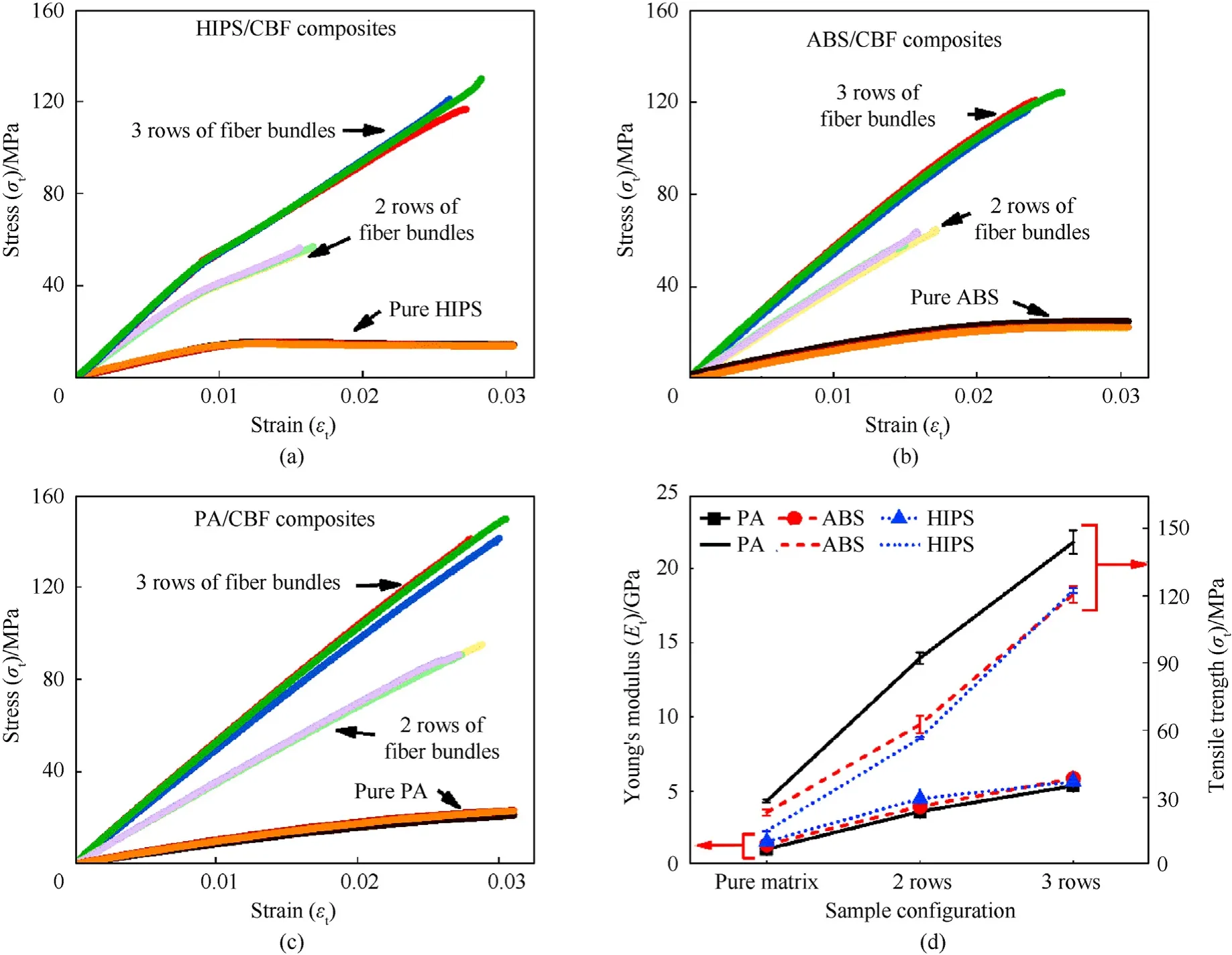
Fig.4.Stress-strain curves of 3D printed (a) HIPS/CBF composites,(b) ABS/CBF composites,(c) PA/CBF composites,and (d) Comparison of mechanical properties of different configurations.The solid line represents Young's modulus and the dashed line represents tensile strength.
Both the Young’s modulus and tensile strength of pure thermoplastic specimens are significantly improved after the addition of CBF.This manifests that high volume fraction CBFs can bring about an obvious mechanical enhancement of the 3D printed specimens even if CBFs only have a low degree of infiltration.Moreover,it should be noted that the Young's modulus of CBFreinforced HIPS composites is higher than that of CBF-reinforced ABS composites and CBF-reinforced PA composites,but its tensile strength is smaller.This is attributed to the better bonding ability of the PA matrix and ABS matrix with CBF fibers,which maintains the integrity of the specimen during tensile process (as shown in Fig.A1 in the Appendix),resulting in a larger failure strain of the specimen.This leads to a higher tensile strength of the sample.In addition,the Young’s modulus and tensile strength of the sample with 3 rows of fiber bundles are higher than those with 2 rows of fiber bundles.This can be ascribed to the difference in fiber content.
3.2.2.Analysis of fracture morphology of tensile specimen
Fig.A1(a)-Fig.A1(c)in Appendix 1 shows the morphology of the 3D printed composites after being subjected to tensile fracture.It is found that the fracture position tends to appear at the neck position.Melenka[16]et al.argued that because of the starting position of fiber lies at the neck position,thus it is prone to break at the neck position.Contrary to this,even the starting position of the basalt fiber is changed to other positions,the specimens still tend to break from the neck.Tensile tests were subsequently performed on straight-arrangement fiber reinforced HIPS composites to investigate the effects of fiber arrangement manner at the neck on the mechanical properties of the samples.The comparation of the stress-strain curves,fracture images and mechanical indicators between straight-arrangement fiber reinforced HIPS composites and non-straight-arrangement fiber reinforced HIPS composites were shown in Appendix 3.As can be seen in Fig.A3,samples still break from the neck when the fibers are organized in a straight manner.However,the integrity of the sample is better maintained.As shown in Table A2,the straight-arrangement fiber reinforced HIPS composites have a comparable Young's modulus to the nonstraight-arrangement fiber reinforced HIPS composites,but larger tensile strength and fracture strain were attained.When the fibers were arranged in straight manner,the tensile strength of the composites with 3-rows of fiber bundles increased by about 45.7% compared with the non-straight-arrangement manner,while the tensile strength of the composites with 2-rows of fiber bundles increased by about 52.96%.In addition,the fracture strain of the composites with 3-rows of fiber bundles increased by about 35.56%,while the fracture strain of the composites with 2-rows of fiber bundles increased by about 42.51% compared with the nonstraight-arrangement manner.This indicates that the straight arrangement manner of CBF fibers at the neck of the specimen has a positive effect on the tensile strength and fracture strain of the specimen.
SEM has been used to characterize the fracture morphology of the 3D printed composite specimens as shown in Fig.5(a)-Fig.5(c).Fig.A1 and Fig.5(a)show that the HIPS/CBF composites undergoes serious matrix cracking and shell layer cracking.The surfaces of pull-out fibers are clean,implying that interfacial bonding between CBFs and the thermoplastic matrix is weak as observed from Fig.5(a)-Fig.5(c).Moreover,the fracture surface of the PA/CBF composites in Fig.5(c)is relatively smoother than those in Fig.5(a)and Fig.5(b).In general,it can be discovered that as compared with 3D printed HIPS/CBF and ABS/CBF composites,PA/CBF composites exhibit the best ductility and thereby preserve the integrity of PA/CBF composites.
3.2.3.Elastic modulus and tensile strength prediction for CBF reinforced thermoplastic composites
The rule of mixtures (ROM) has been implemented in order to predict the elastic modulus and tensile strength of CBF reinforced 3D printed composites.As shown in Fig.2(c),the CBF reinforced 3D printed composites can be classified into several different regions and each layer has its individual elastic modulus.Since the “shell layer”,“solid layer”and “filling layer”are made from the same thermoplastic matrix,and the composites consist of the matrix and the continuous fiber,thus according to the ROM,the predicted Young’s modulus ECand tensile strength XCare given by
whereVfis the volume fraction of the fiber;EfandEmare Young’s moduli of the fiber and the matrix respectively;Xfand Xmare the tensile strength of the fiber and the matrix,respectively.Further,since the failure strain of the polymer matrix is higher than the fiber failure strain,and fiber failure means composite failure.Therefore,Eq.(2) can be rewritten as
where the matrix tensile strength (σ(εf)m) represents the corresponding stress of the matrix at the fracture strain of the composite[47].This method is also known as equal strength analysis model(ESA).Such a model is developed based on three main assumptions:(a)linear elastic behavior until failure;(b)equal longitudinal strain in fiber,matrix,and composite;and (c) the load-carrying capacity of matrix beyond fiber failure is negligible [47].Moreover,the expression of fiber volume fraction can be estimated by
wheredis the diameter of basalt monofilament fiber,His the gauge length,Nfiberis the number of monofilament fibers in the basalt fiber filament,Nconis the number of fiber bundles in the fiber layer during 3D printing,Nlayeris the number of fiber layers,Tis the thickness of the sample,Wis the width of the sample.Table 2 gives the typical mechanical properties of continuous basalt monofilament fibers and the matrix.Table 3 shows the Young’s modulus and tensile strength of 3D printed composites estimated by ROM.It can be seen that the Young’s modulus and tensile strength of the 3D printed samples with 2 rows of fiber bundles are lower than those with 3 rows of fiber bundles.This is consistent with the trend of the results obtained in the experiments(Table 1).A comparison of the modulus and strength has been made between the experimental and theoretical predictions and are plotted together and shown in Fig.6.

Table 2 Mechanical properties of basalt monofilament fiber and matrix.

Table 3 Mechanical properties of the CBF reinforced composites predicted by ROM.
As observed from Fig.6(a)and Fig.6(b),the experimental results of Young’s modulus and tensile strength are always lower than the ROM prediction.This indicates that although CBF filament has high fiber volume fraction,nonetheless its low degree of infiltration has an adverse effect on the mechanical properties.Besides,for the same thermoplastic matrix,both the experimental and the theoretical prediction results show that the increase in fiber content can significantly improve the elastic modulus and tensile strength.Moreover,the prediction of Young’s modulus by ROM is close to the experiments,whereas the prediction of tensile strength has a large deviation from the experiments.The strength can be affected by various factors,such as non-straight arrangement of continuous fibers,insufficient bonding ability between fibers and matrix caused by low degree of infiltration and microcracks inherent in 3D printed parts,etc.[15].
A comparison has also been made between current work and those from the published results of composites fabricated by the FDM process[45,46,50-53].As observed from Fig.7,it can be seen that the composites fabricated with continuous fibers can significantly improve the mechanical properties of the matrix whereas the role of short fibers or 2D nanomaterial in enhancing Young’s modulus and tensile strength is less pronounced.
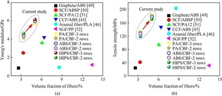
Fig.7.(a) Young’s modulus and (b) tensile strength of CBF reinforced composites in current work as compared with the those fabricated by FDM process [45,46,50-53].
3.3.Flexural properties of CBF reinforced thermoplastic composites
3.3.1.Flexural test results
The flexural properties of CBF reinforced composites in five different configurations (Pure matrix,CBF-S90/matrix,CBF-S45/matrix,CBF-S0/matrix,CBF-G/matrix) have been characterized to investigate the effects of fiber printing direction and the matrix type.Fig.8(a)-Fig.8(c) represent the stress-strain curves of CBF reinforced HIPS,ABS,and PA thermoplastic composites under three-point bending load,respectively.Different from the normally observed direct fracture in fiber-reinforced laminates [54],3D printed CBF reinforced thermoplastic composites exhibit obvious plastic behavior.According to the ASTM D790 standard,the threepoint bending test is terminated when the maximum strain on the outer surface of the specimen reaches 5%,or the test is terminated when a fracture occurs before the maximum strain is reached[43].The flexural strength and modulus are given by

Fig.8.Stress-strain curves of (a) HIPS/BF,(b) ABS/BF and (c) PA/BF composites;and (d) Comparison of mechanical properties under different configurations.
wherePis the load applied by the loading head,Lis the span,bis the width of the sample,dis the thickness of the sample,Dis the deflection at the midpoint of the specimen in the middle of the supporting span.
It can be seen from Fig.8(a)-Fig.8(c)that HIPS/BF-S0 and HIPS/BF-G composites reach the yielding before the termination of the experiment,the rest of the composites do not reach yield or fracture during the whole experiments.For HIPS/BF-S0 and HIPS/BF-G,the flexural strength can be calculated by using the corresponding flexural stress at the yield point.For other samples,their flexural stress and the corresponding flexural moduli at the strain of 5% are taken for comparison(Fig.8(d)).
Fig.8(d) depicts the comparison of the flexural modulus and flexural stress of the 3D printed composites at the strain of 5%.It can be seen that both the modulus and the stress have been enhanced after the addition of CBF.For example,the flexural modulus of HIPS/CBF composites increase from 1.275(pure matrix)to 1.327 (HIPS/CBF-S90),1.604 (HIPS/CBF-S45),2.760 (HIPS/CBFG) and 3.675 GPa (HIPS/CBF-S0),corresponding to an increase by 4.08%,25.80%,116.47% and 188.24%,respectively.Among them,the S0 printing direction gives the largest enhancement of the flexural modulus and this is consistent with the results reported elsewhere[55].The same trends have been observed with 3D printed ABS/CBF and PA/CBF composites.On the other hand,the flexural stress of HIPS/CBF composites at the strain of 5% increases from 22.83(pure matrix) to 24.43 (HIPS/CBF-S90),26.87 (HIPS/CBF-S45),46.68(HIPS/CBF-G) and 42.34 MPa (HIPS/CBF-S0),corresponding to an increase by 7.01%,17.70%,104.47% and 85.46%,respectively.Among them,the G printing direction delivers the highest enhancement of the flexural stress.Similar trends have been also observed with 3D printed ABS/CBF and PA/CBF composites.
3.3.2.Failure morphology analysis offlexural specimens
In order to study the failure behavior,SEM and OM have been used to probe into the inner and outer surfaces of the composites after being subjected to the three-point bending test.The outer surface of the specimen was stretched while the inner surface was compressed.Therefore,“tensile”represents the outer surface of the specimen and “compress”represents the inner surface of the specimen.
(i) Failure behavior of 3D printed HIPS composites
As observed from Fig.9(a)and Fig.9(b),there exist cracks on its outer surface of pure HIPS.In contrast,there exist a large number of stress whitening zones and the breakage of the plastic filament on the inner surface of the HIPS/BF-S0 composites (Fig.9(c) and Fig.9(d)).A large number of crazes have been formed within the polymer plastic along the vertical direction of the stress under the action of external force and the refractive index of the material has changed [56,57].The incident light is even completely reflected within the severely deformed area and thus the stress whitening can be observed macroscopically.In fact,the nature of crazing and stress whitening is identical but exhibits in a different way[57].As observed from Fig.9(e)and Fig.9(f),HIPS/BF-S45 composites have obvious 45°cracks on the outer surface,and there are a large number of stress whitening regions near the cracks and numerous fiber bundles have been exposed from the cracks.For the HIPS/BF-S90,transverse cracks have been generated on the outer surface when the fiber laying angle is 90°and there was stress whitening around the crack (Fig.9(g) and Fig.9(h)).A certain range of stress whitening also appears on the inner surface of the HIPS/BF-G composites and there exist cracks of molten plastic filaments on the inner surface as observed from Fig.9(i) and Fig.9(j).
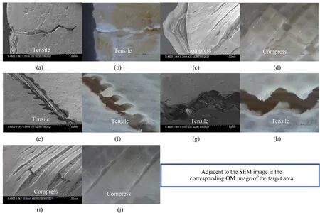
Fig.9.SEM and OM images of the fractured surfaces of the three-point bending samples: (a)-(b) Pure HIPS,(c)-(d) HIPS/BF-S0 composites,(e)-(f) HIPS/BF-S45 composites,(g)-(h) HIPS/BF-S90 composites and (i)-(j) HIPS/BF-G composites.“Tensile”represents the outer surface of the specimen while “compress”represents the inner surface.
(ii) Failure behavior of 3D printed ABS composites
Fig.10(a)-Fig.10(j) show the fracture morphology of the 3D printed ABS/CBF composites after being subjected to three-point bending.Different from the 3D printed pure HIPS specimens,only a small part of stress whitening area appears on the outer surface of pure ABS specimens (Fig.10(a) and Fig.10(b)),and no obvious cracks can be observed.A similar phenomenon happens to ABS/BF-S0 (Fig.10(c) and Fig.10(d)) and ABS/BF-S45 (Fig.10(e) and Fig.10(f)).This is due to the fact that until the strain on the outer surface of the sample reaches 5%,the stress still does not reach the breaking strength and can only produce crazes.It can be seen from Fig.10(g) and Fig.10(h) that the ABS/BF-S90 composites have a transverse corrugated stress whitening area on its outer surface.As observed from Fig.10(i) and Fig.10(j),a network-like stress whitening zone appears on the outer surface of the ABS/BF-G sample,and a certain degree of plastic zone appears on the inner surface.
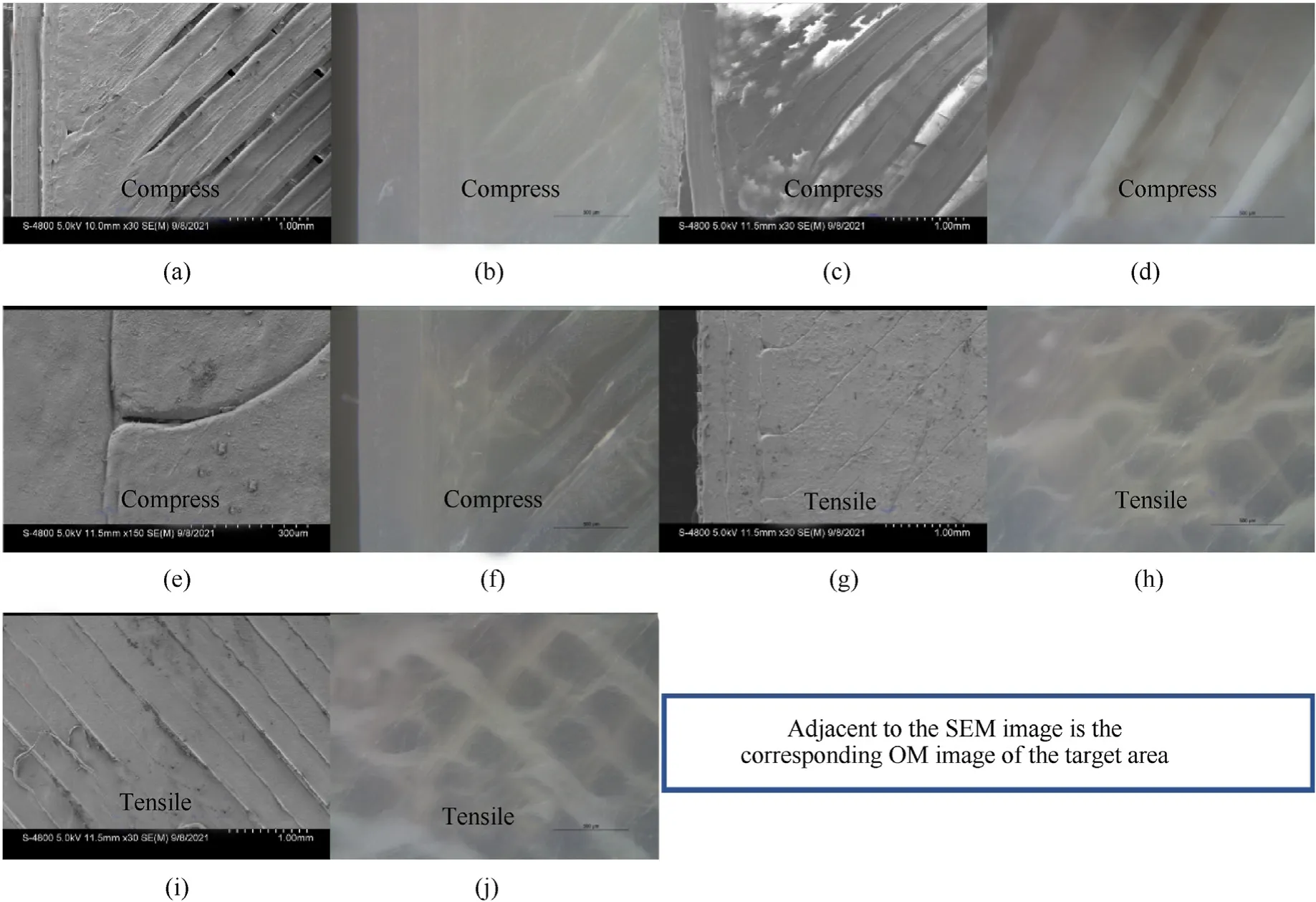
Fig.10.SEM and OM images of the fractured surfaces of the three-point bending samples:(a)-(b)Pure ABS,(c)-(d)ABS/BF-S0 composites,(e)-(f)ABS/BF-S45 composites,(g)-(h)ABS/BF-S90 composites and (i)-(j) ABS/BF-G composites.“Tensile”represents the outer surface of the specimen while “compress”represents the inner surface.
(iii) Failure behavior of 3D printed PA composites:
As shown in Fig.11(a)-Fig.11(e) and Fig.A2(a)-Fig.A2(e) (in Appendix),different from 3D printed HIPS/CBF and ABS/CBF composites,only the inner surface of the PA/CBF composites exists slits between the molten thermoplastic filaments,and there is no obvious damage or even obvious stress whitening on the outer surface.From the tensile stress-strain curves of 3D printed pure HIPS,ABS and PA,it can be seen that under the same tensile loading,yielding happens to pure HIPS first,followed by ABS and finally PA.This indicates that the elastic section of the PA material corresponds to a larger range of strain and that PA has better flexibility and reusability.
4.Conclusions
In this work,the 3D printing thermoplastic composites with high volume fraction basalt fiber have been successfully prepared by the fused deposition modelling(FDM)method.The results show that.
(1) high volume fraction CBFs can bring about an obvious mechanical enhancement of the 3D printed specimens even if CBFs only have a low degree of infiltration.In addition,PA/CBF composites have the best ability to maintain material integrity under high stress,followed by ABS/CBF composites,and finally HIPS/CBF composites.
(2) The ROM's prediction of the longitudinal Young's modulus of the 3D printed specimens reasonably agrees with experimental ones while the prediction of the longitudinal tensile strength exhibits a relatively large discrepancy due to the non-straight arrangement of continuous fibers and insufficient bonding ability between fibers and matrix.
Moreover,the three-point bending tests show that the fiber printing direction has a significant effect on the flexural modulus of the 3D printed composites.Compared with the pure thermoplastic matrix,the S0 (0°) printing direction has the most dramatic enhancement of the flexural modulus of the 3D printed PA/CBF,HIPS/CBF and ABS/CBF composites,increasing by 520.77%,188.24% and 236.08%,respectively.Moreover,compared with the thermoplastic matrix,the G (0/45/90/-45/0/45/0/45/90/-45/0°) printing direction is the most favorable for the enhancement of flexural stress of 3D printed PA/CBF,HIPS/CBF and ABS/CBF composites,increasing by 189.43%,104.47% and 68.53%,respectively.
Through OM and SEM observations,the failure modes of the specimens with high volume fraction basalt fiber mainly include the debonding between the fiber and the matrix,the stress whitening of the matrix and the cracks of the molten thermoplastic filaments.
Author credit statement
Hang Zhang: Investigation,Methodology,Formal analysis,Data Curation,Writing -original draft.Weifu Sun: Conceptualization,Funding acquisition,Methodology,Supervision,Writing-review&editing.All authors have given approval to the final version of the manuscript.
Declaration of competing interest
The authors declare that they have no known competing financial interests or personal relationships that could have appeared to influence the work reported in this paper.
Acknowledgements
The authors acknowledge the financial support from the National Key Research and Development Program of China(grant no.2020YFA0711800),National Natural Science Foundation of China(grant no.11802027),State Key Laboratory of Explosion Science and Technology (grant no.YPJH20-6,QNKT20-01,JCRC18-01),BITBRFFR Joint Research Program (BITBLR2020018) and Beijing Institute of Technology Research Fund.
Appendix 1
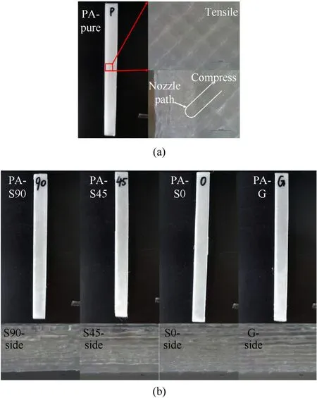
Fig.A2.The OM images of the failure behavior of:(a)the outer surface (tension)and the inner surface (compression)of PA specimens after three-point bending experiment;and side views of: (a) PA/BF-S90;(c) PA/BF-S45;(d) PA/BF-S0;(e) PA/BF-G.
Appendix 2

Table A1 Print parameters in the present work.
Appendix 3
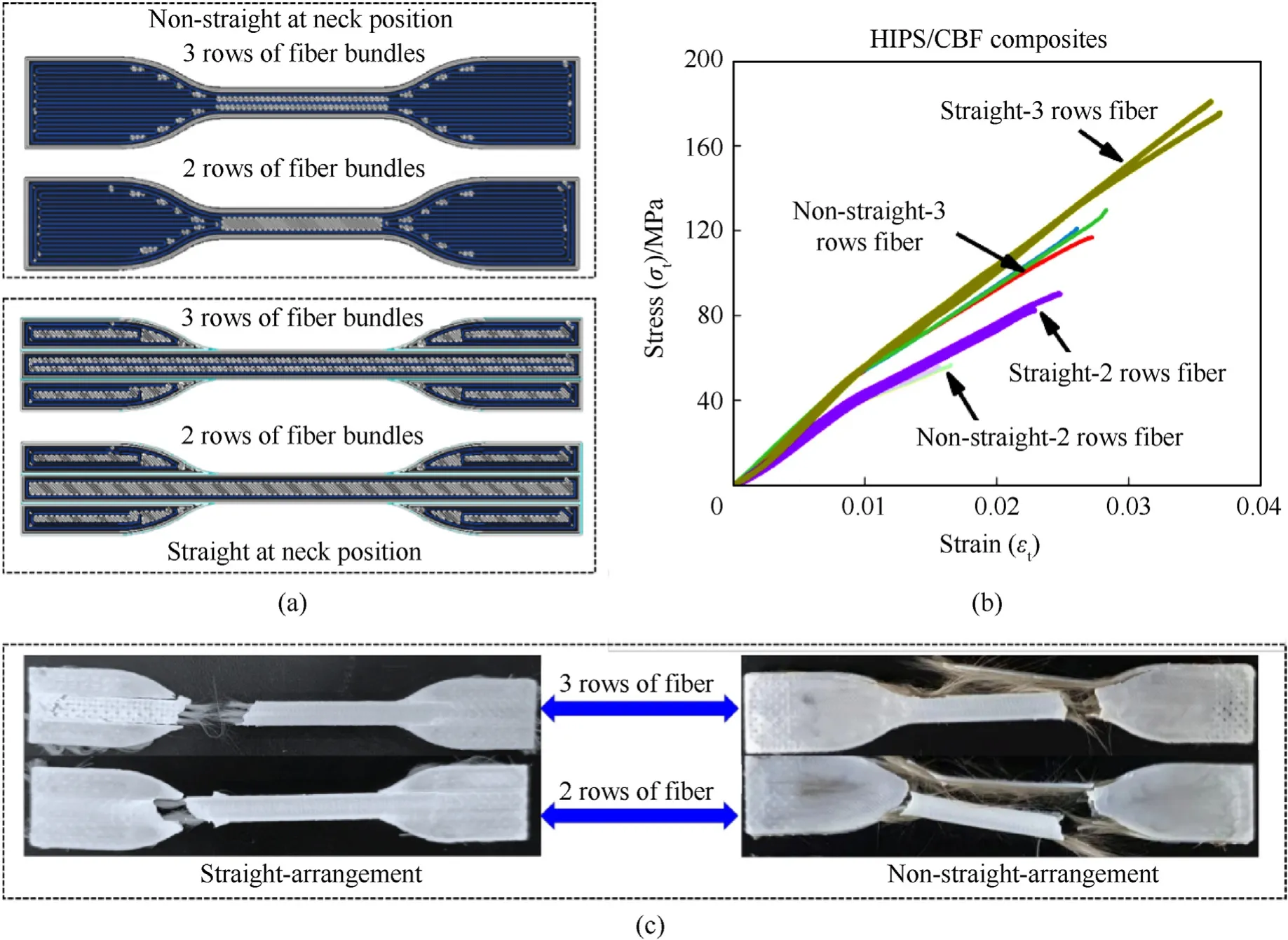
Fig.A3.(a)Schematic diagram of the samples with non-straight arrangement and straight arrangement fibers at the neck.The way to realize the straight arrangement of the fibers is to cut the geometric model of the sample into five parts,and the fibers are printed in the five parts respectively,which not only realizes the straight arrangement of the fibers but also ensures the geometric integrity of the sample.(b) The comparation between stress-strain curves of straight-arrangement fiber reinforced HIPS composites and non-straightarrangement fiber reinforced HIPS composites.(c) The comparation between fracture images of straight-arrangement fiber reinforced HIPS composites and non-straightarrangement fiber reinforced HIPS composites.
杂志排行
Defence Technology的其它文章
- An energetic nano-fiber composite based on polystyrene and 1,3,5-trinitro-1,3,5-triazinane fabricated via electrospinning technique
- Dynamic response of UHMWPE plates under combined shock and fragment loading
- Aerial multi-spectral AI-based detection system for unexploded ordnance
- Model-based deep learning for fiber bundle infrared image restoration
- Robust design and analysis for opto-mechanical two array laser warning system
- Combustion behavior and mechanism of molecular perovskite energetic material DAP-4-based composites with metal fuel Al
