Deep learning-based LPI radar signals analysis and identification using a Nyquist Folding Receiver architecture
2023-01-18TaoWanKailiJiangHaoJiBinTang
Tao Wan,Kai-li Jiang,Hao Ji,Bin Tang
School of Information and Communication Engineering,University of Electronic Science and Technology of China,Chengdu,611731,China
Keywords:Nyquist folding receiver Ultra-wideband Deep learning Time-frequency analysis Identification Classification
ABSTRACT Nyquist Folding Receiver(NYFR)is a perceptron structure that realizes a low probability of intercept(LPI)signal analog to information.Aiming at the problem of LPI radar signal receiving,the time domain,frequency domain,and time-frequency domain problems of signals intercepted by NYFR structure are studied.Combined with the time-frequency analysis(TFA)method,a radar recognition scheme based on deep learning(DL)is introduced,which can reliably classify common LPI radar signals.First,the structure of NYFR and its characteristics in the time domain,frequency domain,and time and frequency domain are analyzed.Then,the received signal is then converted into a time-frequency image(TFI).Finally,four kinds of DL algorithms are used to classify LPI radar signals.Simulation results demonstrate the correctness of the NYFR structure,and the effectiveness of the proposed recognition method is verified by comparison experiments.
1.Introduction
To solve the problem that the current electronic warfare (EW)receivers cannot simultaneously receive and recognize the low probability of intercept(LPI)radar signals,we associate with a new type of receiver,called the Nyquist Folding Receiver (NYFR).This paper intends to start from the perspective of time-frequency analysis,combined with relevant knowledge of image processing,analysis,and processing of LPI radar signals are completed.Moreover,the start-of-the-art deep learning technology is employed to realize the identification of LPI radar signals.
In recent decades,the demand for wireless devices has shown rapid growth [1],including Internet of things applications such as the Internet of vehicles and smart cities in civilian applications[1-3],and the electromagnetic spectrum use for radar,communications,and EW in military applications[4,5].The electromagnetic spectrum is a limited resource,which is essential for communications and radar [6].As far as non-cooperative signal processing is concerned,since future communication equipment and radar equipment tend to be in the same frequency band [7],how to accurately identify signals in the frequency band is a long-term and urgent topic.
The objects of EW are electronic devices and systems in the electromagnetic spectrum,which aim at obtaining,transmitting,and utilizing information,including various electronic warfare monitoring sensors and communication systems,etc.[8].Therefore,the range of the electromagnetic spectrum is often faced with an LPI electromagnetic environment [9,10].However,it is difficult for electronic warfare (EW) receivers to simultaneously intercept ultra-wideband signals from several GHz to tens of GHz,and it is costly to adopt multiple analog-to-digital converter(ADC)modes to achieve [11].Compressed sensing (CS) provides a potentially feasible solution,through sub-Nyquist sampling at the information rate,each time only a part of the monitored spectrum is used[12].Based on this,Fudge et al.proposed an analog-to- information theory and the Nyquist folding receiver (NYFR),which has the characteristics of low power consumption and reconstruction of complete LPI signals[13,14].Unlike CS,signals can still retain their physical meaning after sampling by NYFR compression.
Given this,many scholars have carried out a series of studies on the NYFR structure.As far as EW is concerned,some studies have investigated radar signals detection via NYFR [15,16],parameter estimation of linear frequency modulation (LFM) signals [17-20],parameter estimation of frequency hopping signals [21,22],and time of arrival (TOA) estimation [23].The simulation results show that the performance of detection and parameter estimation are both superior in specific scenarios.Due to the existence of the local oscillator(LO),NYFR has a modulation effect on the original signal after folding.Generally speaking,the LO is sinusoidally modulated[14],the change of LO modulation has a great impact on the identification and parameter estimation accuracy of the original signal [21].However,few scholars have done modulation type recognition research on radar signals for specific LO modulation via NYFR.Therefore,it is particularly critical to study the type of intrapulse modulation via NYFR.
So far,there have been many modulation type identification methods for radar signals,most of which are aimed at LPI radar signals,mainly including frequency modulation and phase modulation signals[24].By converting these LPI radar signals into timefrequency images (TFI) [25-27],spectral correlation [28],and visibility graphs images [29],etc.,and using machine learning methods to identify them,the recognition performance is quite excellent.However,these methods have a common problem,i.e.,how the signal is received.Moreover,NYFR has superior structure and performance to receive LPI radar signals,thereby allowing further research and development.
Deep learning (DL) is the process of learning to obtain internal rules and representation levels in training samples,and use this information to complete the judgment and recognition of text,images,sounds,etc.[30].DL is widely used in various fields,and it is a new development direction in the field of machine learning[31,32].In DL,there are common autoencoders,convolutional neural networks (CNN),recurrent neural networks,etc.[32].Among them,CNN is a type of feedforward neural network that includes convolution calculation and has a deep structure,and it is one of the most considerably used image recognition algorithms.In the application of CNN,LeNet-5[33],AlexNet[34],GoogLeNet[35],ResNet[36] and other networks are the most widely used.
Many scholars investigate the electromagnetic spectrum and DL on the interdisciplinary,some for radio frequency (RF) equipment[37],some for cooperative spectrum [38],and some for wireless communication systems[39].Taking radar signal recognition as an example,the usual approach is to first represent the signal as TFI,and then use DL algorithms such as CNN to identify them[40-42].Based on time-frequency analysis(TFA),this paper proposes an LPI radar signal modulation type recognition technology via NYFR architecture,including nine types of LPI radar modulation type signals,namely modulated pulse (MP),linear frequency modulation(LFM),binary phase shift keying (BPSK),binary frequency shift keying (BFSK),V-shaped frequency modulation,LFM/BPSK combination modulation,Costas frequency modulation,Frank phase encoding,and no signal.This method first uses the short-time Fourier transform (STFT) [43] to convert the signal after NYFR folding into TFI.Then uses a variety of DL algorithms to identify them.Finally,verify the effectiveness of the algorithm through comparative experiments.
In this paper,our main contribution is to take into account the problem of signal receiving.Unlike the channelization receiver,the signal receiving of NYFR is lower speed ADC sampling,more complete,cheaper,and the receiving of LPI signal can be realized.Therefore,based on NYFR architecture,we investigate the relationship between the noise-only signal after NYFR folding and its output power.Based on this,the relationship among the time domain,frequency domain,and time-frequency domain of various LPI radar signals after NYFR folding are studied.Also,STFT technology is used to convert the signals into TFI,and the start-of-theart DL technology is used to complete the recognition of various LPI radar signals.In the whole process,the proposed algorithm,by comparison with other algorithms,is not only improved the signal recognition probability.But more significantly,this paper has completed the EW receiver receiving of LPI signal,thereby some related analysis and processing.The current ADC sampling rate is low,and the difficulty of realizing channelization in the frequency domain is solved.This study provides a theoretical basis for the low sampling rate of ADC and the difficulty of channelization.
The remaining paper is structured as follows.Section II introduces the structure of NYFR,frequency domain,and timefrequency domain of the LPI radar signals.Section III describes the signal recognition algorithm based on the DL.Section IV presents the validation of the proposed algorithm including the simulation experiment setup,results,and discussion.Section V concludes the paper and presents the potential future research directions.
2.Signal model
2.1.NYFR structure
The NYFR structure is a secondary sampling structure[13,14],as shown in Fig.1,which uses the zero-crossing rising (ZCR) edge to control the RF sample clock and generate the LO,p(t).Assume that the received RF signal is r(t),it is filtered by a wideband filter H(ω)to remove components outside the monitored bandwidth.The frequency band signal x(t)is sampled using the unquantized pulse train,p(t),with an average frequency of fs1.Finally,the output signal y(t)is obtained by filtering the signal through a continuoustime interpolation filter F(ω),which is also used as an anti-aliasing filter of the ADC,with a sampling frequency of fs2(fs2≥fs1).Finally,a conventional low-speed ADC is used for sampling.
Assume that the signal x received and processed by the NYFR front-end can be expressed as

where the carrier frequency of the signal is ωc,and the phase is φc(t),n(t)denote a complex additive white Gaussian noise(AWGN).Then,when the non-uniform sampling modulation information of LO remains unchanged,a simplified LO non-uniform sampling pulse train expression can be expressed as [17].
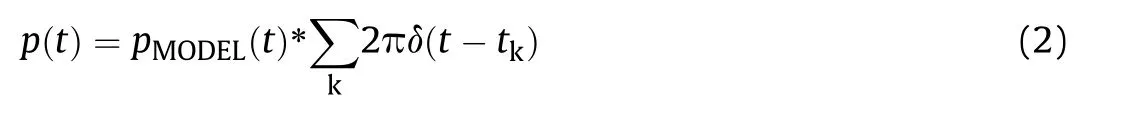
where pMODEL(t) is the template pulse and * denotes the convolution operation.The Fourier transform (FT) PMODEL(ω) of pMODEL(t)can be regarded as a constant in the range of k[ωs1-Since the analog output signal y(t) is filtered by multiplying x(t) and p(t),i.e.,

where f(t) is the impulse response function of the low-pass filter,which is the time domain expression of F(ω),and the frequency spectrum of the output signal y(t) is [17].
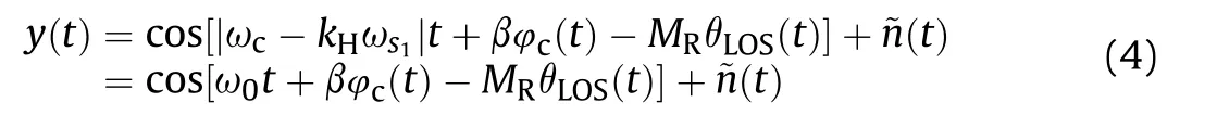
where ω0=|ωc-kHωs1|is the intermediate frequency of the signal after NYFR folding,kHis the Nyquist zone(NZ)where the signal x(t)is located and kH=round(ωc/ωs1),the size of an NZ is ωs1,round(·)represents rounding and rounding,β=Sgn(ωc-ωs1kH),MR=βkHare called modulation scale factor,θLOS(t)=sin(ωθt) is the phase of SFM modulation,~n(t) is AWGN folded from NYFR.
2.2.Signal time domain,frequency domain,time-frequency domain analysis
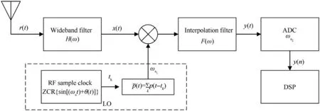
Fig.1.Block diagram of NYFR structure.
Analysis based on [45],since the influence of noise is only the change in the power spectral density,it does not cause the power of the noise to change.Therefore,we ignore the influence of noise in the following analysis.
2.2.1.Modulated pulse (MP) signal
Suppose the expression of an MP signal [24] is

where Ac,ωc,φcare the signal amplitude,carrier frequency,and initial phase respectively.φcis a random variable that obeys a uniform distribution in [0,2π],and Tprepresents the pulse width.Then the FT of xMP(t) can be expressed as

Due to the identity
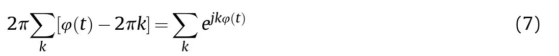
Therefore,transform Eq.(2) into a general expression of LO
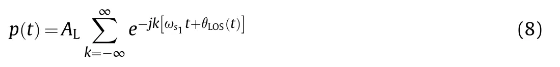
Among them,ALis the magnitude of LO.When ωθ≠0,p(t)can be written as
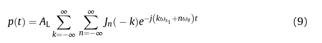
where n is an integer and Jn(·) is the first kind of n -order Bessel function.For the sake of simplicity,the influence of the initial phase of LO is ignored.The initial phase φθis added to LO here and after.Eq.(9) can be rewritten as
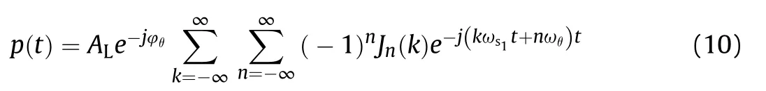
Then the FT of p(t) is
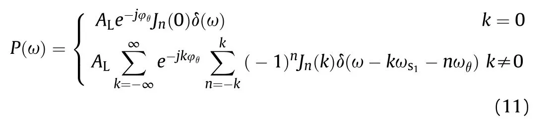
Then after the MP signal passes through the NYFR structure,we can get

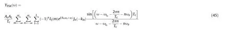
Then the frequency domain expression of yMP(t) is
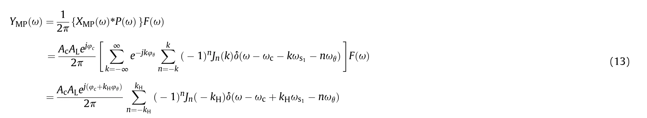
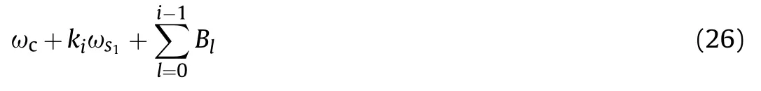
It can be known from the nature of the filter that the signal in the passband is completely preserved,so there is only one NZ spectrum in the end.Observing Eq.(13),we can see that after NYFR folding,the frequency spectrum of the output signal is no longer a single spectral line,but is composed of a series of spectral lines.The frequency spectrum is centered at ωc-kHωs1,and ωθis the interval,with m spectral lines on the left and right.That is,NYFR essentially shifts the frequency spectrum of the input signal,moving the signal from the kH-th NZ to the 0-th NZ,that is,to near the zero frequency.Through Eq.(13),perform inverse Fourier transform(IFT)to obtain the folded time-domain form of MP signal as
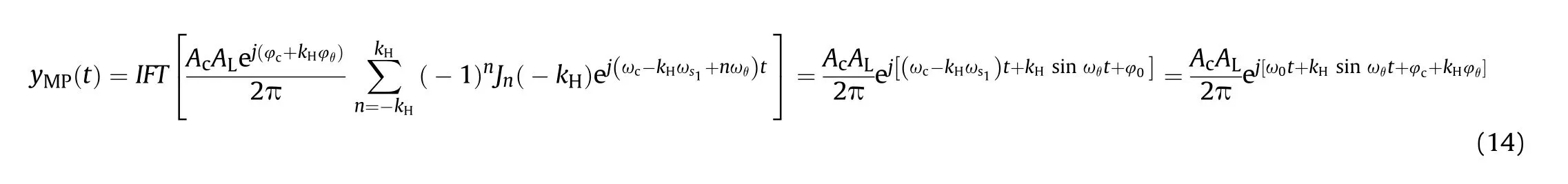
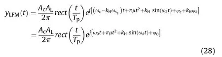
where ω0=ωc- kHωs1,after the MP signal folding by the NYFR structure,the amplitude AcAL/2π of the output signal,the initial phase φ0is the sum φc+kHφθof the signal initial phase and the LO kHtimes initial phase.Therefore,for a single pulse MP signal,the main effect of modulating the LO on its intra-pulse parameters is that the amplitude of the LO amplitude is introduced.The carrier frequency is no longer ωc,but becomes ωc- kHωs1,and introduce kHtimes sin ωθt modulation on the phase.Through Eq.(14),the time-frequency relationship of MP signal can be obtained as

It can be seen that the folding frequency adds a cosine modulation with an amplitude of kHωθto the fixed frequency ω0.Fig.2(a)shows the TFI of the MP signal after NYFR folding,which is implemented by STFT.The STFT [43] is commonly used in TFA technology,and its general expression is
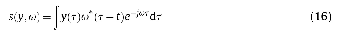
where y(t)is the input signal,ω*(t)is the complex window function,and s(y,ω)is the output result of STFT.Then,substituting Eq.(5)into Eq.(3),and the solved signal output form is shown in Eq.(4).
2.2.2.Linear frequency modulation (LFM) signal
Take the NYFR structure into consideration,the discussion of LFM signals[24]generally consists of two cases.The one is the LFM signal that does not cross NZ,and the other is the LFM signal that crosses NZ.We first discuss the LFM signal that does not cross NZ,it can be expressed as
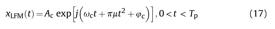
where μ is the slope of LFM.It can be expressed as a rectangle function
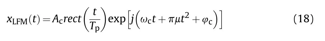
where rect(u) is the rectangular amplitude function
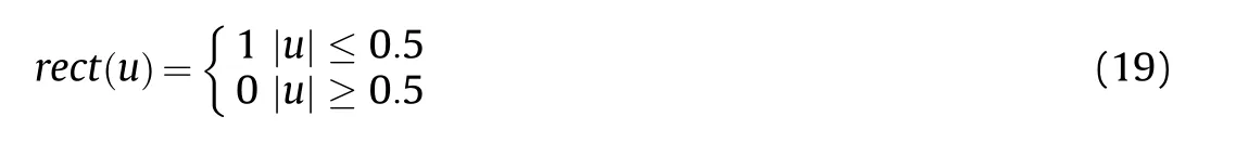
In the case of a large compression ratio,the spectral function of the LFM rectangular pulse signal can be expressed as
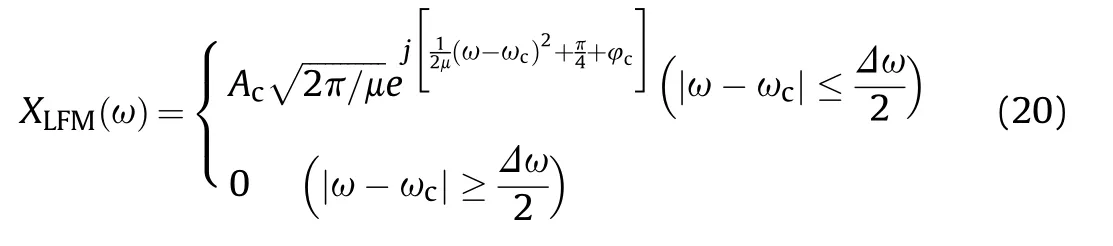
After folding the LFM signal by NYFR,the spectrum of the LFM signal can be obtained as

Similar to the MP signal,the frequency spectrum of the folded LFM signal is moved to 0NZ,the starting frequency becomes ωckHωs1,and the amplitude is compared with the original input LFM signal,plus the influence of the Bessel function value and the amplitude of the LO itself.The FM slope μ is not affected by the NYFR structure.Secondly,for the LFM signal across NZ,the range of the NZ index factor k where the signal is located is determined by F(ω),we can obtain
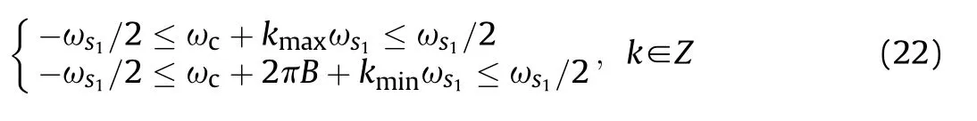
where B=μTpis the bandwidth of LFM.Suppose the index area numbers of different NZ covered by the broadband signal are
Then the corresponding bandwidth in each NZ canbeexpressed as
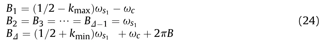
Through the analysis of the LFM signal that does not cross NZ,it can be seen that the slope of the LFM signal remains unchanged,thereby the pulse width in each NZ is

where i=1, 2, …, Δ,the starting frequency in each NZ is
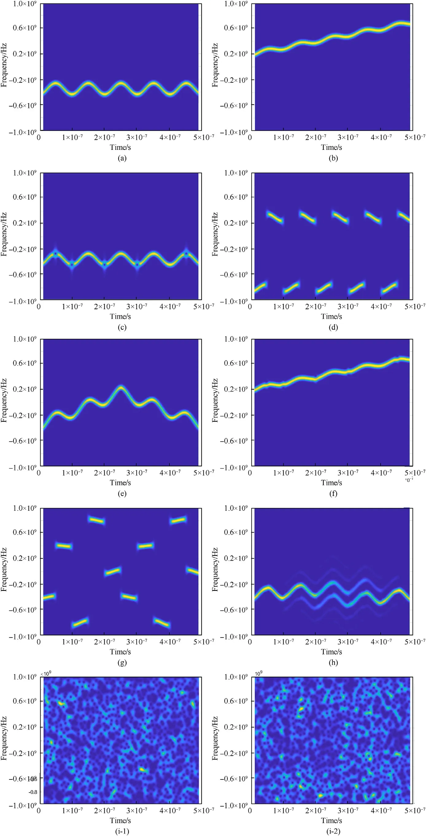
Fig.2.TFIs of nine signals folded by NYFR.(a) MP.(b) LFM.(c) BPSK.(d) BFSK.(e) V.(f) LFM/BPSK.(g) Costas.(h) Frank.(i-1) LPI radar signals at very low SNRs.(i-2) Noise only.
Then it can be known that the frequency domain expression of the folded cross-band LFM signal can be expressed as
According to Eq.(21),the time domain expression of the LFM signal that does not cross the NZ domain can be obtained from IFT as
Among them,ω0=ωc- kHωs1,AcAL/2π and φ0are the initial frequency,amplitude,and initial phase φ0of the folded LFM signal,and the signal slope is still μ.Therefore,the influence of the NYFR structure on the LFM signal is mainly manifested by the addition of SFM modulation to the phase.And move the original signal from high frequency to low frequency.The time-frequency relationship of the LFM signal can be easily obtained by the above formula as

Similar to the MP signal,while increasing the frequency 2πμt modulation,the LFM signal also increases the cosine modulation with the folding frequency amplitude kHωθ.Transform by STFT,and use the TFI to represent the LFM signal received through NYFR,as shown in Fig.2(b).
2.2.3.Phase shift keying (PSK) signal
The complex expression of the PSK signal[24]can be written as

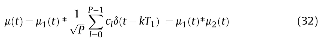
where μ(t) is the complex envelope and φ(t) is the phase modulation function.Take binary phase shift keying (BPSK) as an example,φ(t) only takes two values of 0 and π.Let cl=ejφ(t),the complex envelope of the BPSK signal can be obtained as

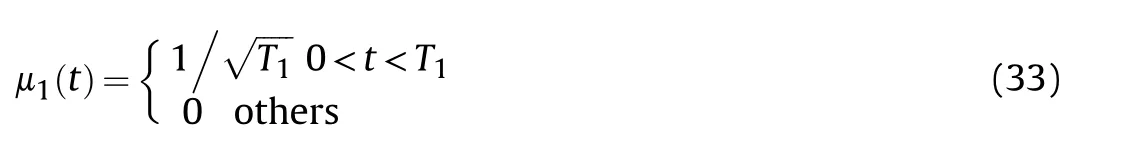
where μ1(t) is the complex envelope of the sub-pulse,T1is the width of the sub-pulse,P is the number of sub-pulses,TP=PT1is the duration of the two-phase coded signal.Using the properties of the Dirc function [44],Eq.(31) can be expressed as
Then the FT of μ1(t) and μ2(t) respectively written as
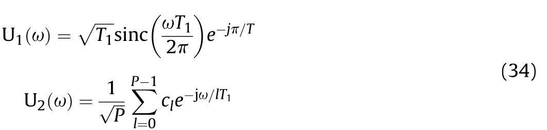
From the convolution theorem,we can obtain
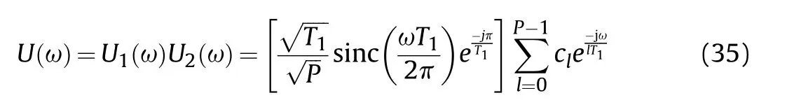
Then
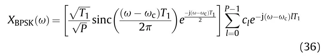
After NYFR folding processing,there are
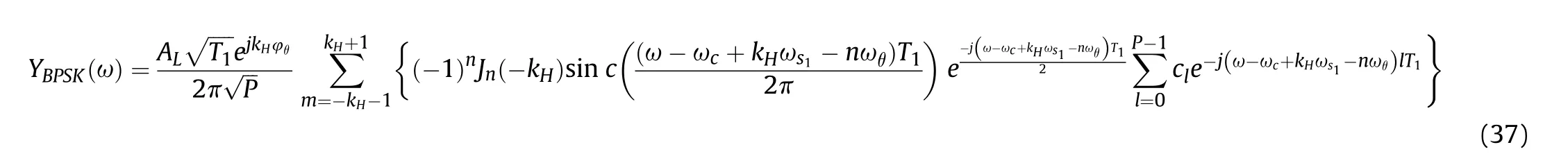
Similarly,the BPSK signal folding to the baseband,and kHoriginal BPSK signal spectra are superimposed with different amplitudes.Performing IFT processing on Eq.(37),the time domain form of the obtained folded BPSK signal can be expressed as
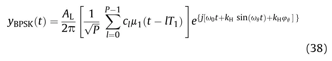
In Eq.(38),the encoded information is the same as the original signal,and the envelope is still μ1(t),the sub-pulse duration is T1,and the amplitude is multiplied by AL/2π.The BPSK signal is moved to the carrier frequency ωc- kHωs1,and the phase becomes kHsin(ωθt)+kHφ.Therefore,in T1time,the BPSK signal timefrequency relationship can be expressed as

Similar to the MP signal,while increasing the frequency 2πμt modulation,the BPSK signal also increases the cosine modulation with the folding frequency amplitude kHωθ.At other times,ωyBPSKis 0.BPSK signal has the characteristic of abrupt change in phase hopping,and the TFI of the signal is obtained by STFT,as shown in Fig.2(c).
2.2.4.Frequency shift keying (FSK) signal
The generation of the FSK signal [24] is to switch the signal between L frequency sources,and its time domain can be expressed as
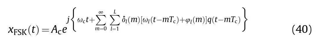
It can be seen from Eq.(40) that the instantaneous relative phase of the FSK signal at a time mTcis φl(m)=ωlmTc+φl,where φlis the initial phase of the l -th frequency source.Therefore,the FSK signal can be simplified as
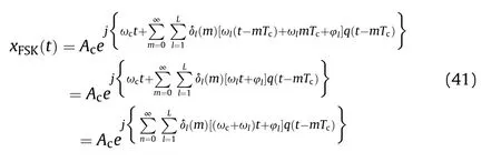
Among them,δl(n)=[δ1(n),δ2(n),…δL(n)] means that only one impulse function in the sequence is 1,and the others are 0.From the nature of the impulse function
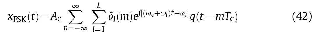
If q(t) is a rectangular wave,satisfy the condition

Then the FT of the FSK signal can be obtained as
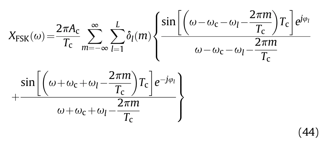
After receiving and processing the NYFR structure,the output frequency domain can be expressed as
where ωl0is the folded center frequency of the l -th folded frequency source.Therefore,when the input signal of NYFR is an FSK signal with a discontinuous phase,the carrier frequency will move to ωc+ωl-kHωs1and each frequency encoding component will increase the LO modulation information.It should be noted that when the binary frequency shift keying (BFSK) signal ωlis an integer multiple of the LO average sampling rate,the folded signal output by NYFR becomes a folded MP signal,and the characteristics of the FSK signal are still maintained in other cases.
The time-domain expression of the folded FSK signal can be obtained by IFT processing from Eq.(45),which can be written as
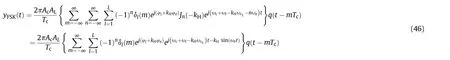
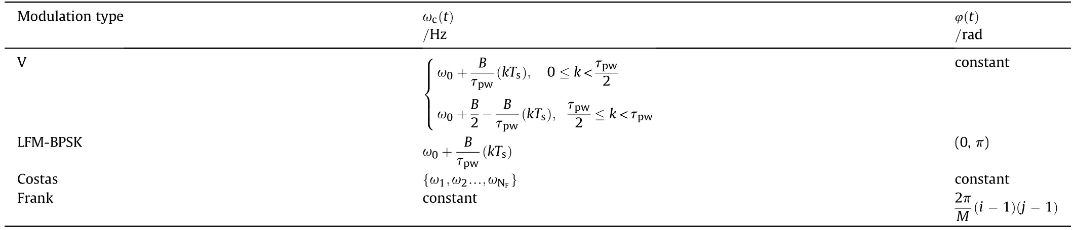
Table 1 Modulation type of radar signal.
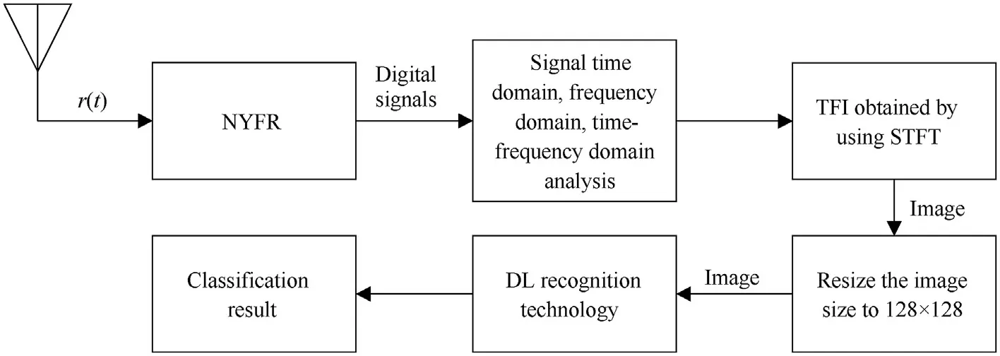
Fig.3.Schematic of LPI radar signal recognition technology.
Considering the BFSK signal,its NYFR output can be obtained as
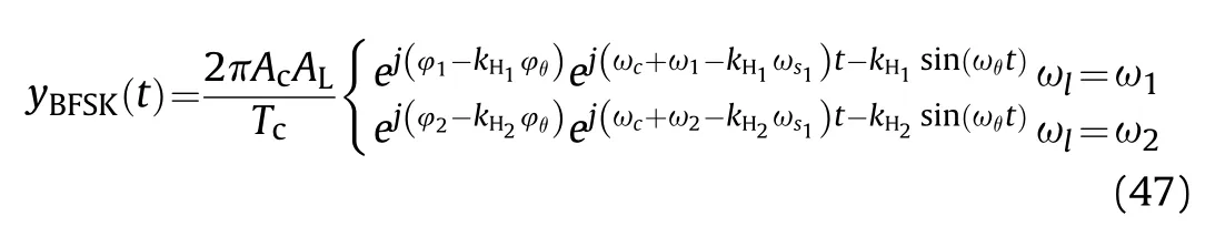
The BFSK signal switches between the two frequency sources,thereby for different frequency hopping intervals Δω=|ω2- ω1|,the NZ index factor has different situations.When Δω is exactly an integer multiple of ωs1,the center frequencies of the BFSK signals after folding will overlap,but they have different bandwidths,which are determined by the size of the NZ index factor.When Δω makes ω1and ω2at the same NZ,the folded signal bandwidth is the same,but the center frequency is not consistent,and spectrum aliasing may exist.Through Eq.(47),the time-frequency relationship of the BFSK signal can be obtained as
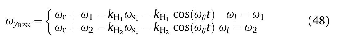
The different frequency points of the BFSK signal simultaneously add cosine modulation with the folding frequency amplitude kHωθ.BFSK signal has the characteristic of mutation in frequency hopping,and the TFI of the signal is obtained by STFT,as shown in Fig.2(d).
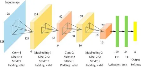
Fig.4.The radar signal modulation type recognition structure based on LeNet-5.
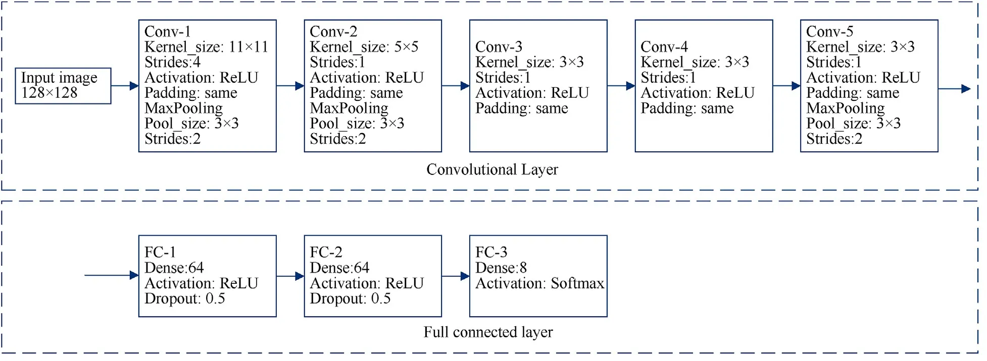
Fig.5.The radar signal modulation type recognition structure based on AlexNet.
The form of V-shaped frequency modulation is almost the same as LFM,except that there is a frequency mutation point in the middle,and then the slope of the signal frequency change with time is opposite to the previous one.LFM-BPSK combination modulation signal increases the phase modulation factor of BPSK based on the LFM signal.Costas is a frequency modulation signal,the analysis is similar to FSK.Frank encoding is a phase-encoded signal,and its signal analysis is similar to PSK.The expressions of these four types of signals can be uniformly written in the form of Eq.(1),where ωc(t) represents the frequency modulation information of the signal,and φ(t) represents the phase modulation information.The corresponding frequency modulation and phase modulation are shown in Table 1.Their time domain and frequency domain analysis is almost similar to LFM,PSK,and FSK.Moreover,there are phase-encoded signals such as polytime codes and polyphase codes [24],which are similarly analyzed with PSK.TFI obtained by using STFT after NYFR folding for V-shaped,LFM/BPSK,Costas,and Frank are shown in Fig.2(e-i).
To experiment with the completeness,considering the LPI characteristic,signals may be low SNRs circumstance,we set when SNR<-15 dB to be not detected,i.e.,no signal.Also,add noise-only signal,the eight modulation types mix with noise-only signal into a new modulation type,that is no signal,TFI obtained by using STFT after NYFR folding for no signal type are shown in Figs.2(i-1)-(i-2).The former is the case when the signal is at very low SNRs,and the latter is the noise-only case.
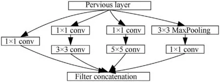
Fig.6.The structure of the Inception module.
3.DL recognition technology
The recognition schematic of the LPI radar signal is shown in Fig.3.First,NYFR intercepts the LPI radar signal and converts it into a digital signal.Then,we perform time domain,frequency domain,and time-frequency domain analysis on various LPI radar signals.Next,the signal is converted to TFI by STFT,and the image is resized to 128 pixel×128 pixel.Finally,DL recognition technology is used to classify various LPI radar signals.In this schematic,DL recognition technology is also a very important link.Then,we introduce the DL recognition framework of this paper.
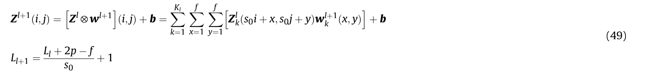
DL is mainly based on the CNN identification framework,which generally includes an input layer,hidden layers,and an output layer,and hidden layers include convolutional layers,pooling layers,and fully connected(FC)layers.The convolutional layer and the pooling layer usually appear alternately [30].The convolution operation is the core in CNN,assume an image I is i× j,then the convolution operation can be expressed as [30].
Among them,(i,j)∈{0,1,…Ll+1},Ll+1is the size of Zl+1,and the sum part is to solve the cross correlation.Zland Zl+1are the feature maps,which are the convolution input and output of the l-th layer,wl+1is the kernel function of the l-th layer,and b is the deviation.The length and width of the feature map are generally assumed to be equal.Z(i,j)is the pixel of the feature map,and K is the number of channels in the feature map,f,s0,and p are respectively expressed as the size of the convolution kernel,the step length,and the number of padding layers,which are the components of the convolution layer parameters.
In the convolutional layer,the activation function is used to assist the expression of features,which can be expressed as [30].
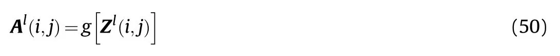
The commonly used activation functions generally include rectified linear unit (ReLU),Leaky ReLU (LReLU),tanh,Sigmoid function,etc.
The function of the pooling layer is generally to select and filter the information transmitted by the feature map.Similar to the description of the feature map of the convolutional layer,the pooling layer is determined by the pooling size,step size,and padding.The most common one is the maximum pooling(MaxPooling) function,which gives the maximum value in the rectangular area.Some use the average value,the weighted average value in adjacent rectangular areas.
The FC layer is the last part of hidden layers,and it is one-way propagation in this layer.The feature map after passing this layer will lose the spatial topological structure and expand into a vector through the activation function [30].For radar signals,the output layer uses the Softmax function to output classification labels.This paper considers four CNN network structures,including LeNet-5[33],AlexNet [34],GoogLeNet [35] and ResNet [36].These networks and structures are introduced below.
3.1.LeNet-5
As a classic CNN structure,LeNet-5 is applied in various fields of recognition processing [33].The signals after NYFR folding are converted into two-dimensional images by STFT,and they are sent to CNN as input images for recognition operation.As shown in Fig.4,we first generate nine modulation signals with a different signal-to-noise ratio (SNR),and the input picture size is 128 pixel×128 pixel.The LeNet-5 network structure can be described as input image- Convolution (Conv)- MaxPooling- Conv- Max-Pooling- FC- FC- output classification results.
3.2.AlexNet
AlexNet [34] was proposed by Alex et al.,in 2012.It is an improved network of LeNet-5.It is composed of 5 convolutional layers,3 pooling layers,and 3 FCs.The activation function uses ReLU,and AlexNet simultaneously uses strategies such as random deactivation and data increase.More importantly,it is the first CNN structure proposed to learn on GPU,so that it can use the parallel computing structure of GPU to perform data training.In this paper,the network structure and parameter settings of AlexNet are shown in Fig.5.
3.3.GoogLeNet
As the number of network layers increases,the complexity and parameters will increase,and the gradient will gradually disappear,leading to the appearance of overfitting.Based on this,GoogLeNet[35]was proposed.The core idea of GoogLeNet is to build multiple inception modules.The inception module mainly uses 1 × 1 convolution to reduce dimensionality and reduce computational complexity.At the same time,multiple convolution and reaggregation on multiple scales can extract features of different scales and accelerate the convergence speed through matrix decomposition.Fig.6 shows the structure of the inception module.It can be found that the structure has four branch structures,and they are all calculated in parallel.Fig.7 shows the radar signal modulation type recognition structure based on GoogLeNet.Through the connection with the inception module,the network operation speed and gradient are constantly updated.Moreover,another advantage of the inception module is that there are two 1×1 convolution side branches in the hidden layer,and the output of the side branches and the trunk are normalized,so that the network gets a regularization effect.
3.4.ResNet
ResNet [36] is proposed because of the continuous increase in the number of network layers,the accuracy of the model will first rise to a saturated state and then decrease.Based on this,a residual network was proposed.This kind of network can use a shortcut connection to make the number of network layers very deep,even reaching more than 1000 layers.The advantage of ResNet is that it provides a shortcut that lead the original network structure with only one propagation path becomes two,which solves the problem of the disappearance of the gradient as the number of connection layers increases.Fig.8 shows the partial structure of ResNet.
Fig.8(a)shows a shortcut connection,and the point is to iterate the information of the first two layers to the current layer at the same time so that the current layer can obtain the gradient of the previous layer or even the previous layers.Fig.8(b)shows the two ways of shortcut connection.The solid line is when the number of layers is the same,the calculation method is y=F(x)+x.If the number of layers is different,as shown by the dotted line in Fig.8(b),the calculation method should be y=F(x)+wx,where w is a convolution operation to adjust the channel dimension of x.Table 2 shows a typical ResNet structure,including 34-layer,50-layer,and 101-layer.This paper uses the 34-layer ResNet structure.
4.Simulation experiment results
4.1.Parameter settings
To evaluate the performance of the classifier,we form simulation data using the following parameters.The sampling frequency ωs=40 GHz,the signal frequency ω0=6.2 GHz,the code rate ωb=2 GHz,the number of symbols N=10,and the duration τpw=N/ωb.For LFM,the signal bandwidth B is τpw,the frequency modulation slope k=1.For BFSK,the{ω1,ω2…,ω10}is{11.2,12.3,11.2,12.3,11.2,12.3,11.2,12.3,11.2,12.3,}GHz,when the radar signal is frequency modulated,the phase information is 0.When the radar signal is phase modulated,the carrier frequency is the signal frequency ω0.For Costas,the{ω1,ω2…,ω10}of Costas is{3,2,6,4,5,1,3,2,6,4} GHz,respectively.In Frank coding,the step number M=10,and the sequence length or compression ratio Nc=M2=100.
For better identifying and extracting different modulation types of radar signals and improve the generalization ability of the network,100 training samples are generated under the signal-tonoise ratio (SNR)=-8 dB:1 dB:7 dB,the sample size is 128 pixel ×128 pixel,A total of 14,400 training samples are generated to complete the training of DL network.To verify the validity of DL for the recognition of intra-pulse modulation type,in the range of SNR from-10 dB to 5 dB,100 test samples are generated for each signal under each SNR,a total of 7200 test samples.
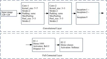
Fig.7.The radar signal modulation type recognition structure based on GoogLeNet.
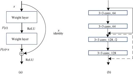
Fig.8.ResNet partial structure.(a) Shortcut connection.(b) Two shortcut connection methods.
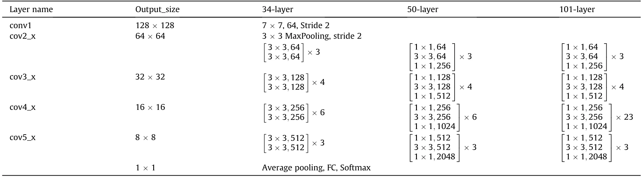
Table 2 The radar signal modulation type recognition structure based on ResNet.
4.2.Four kinds of DL algorithm performance comparison
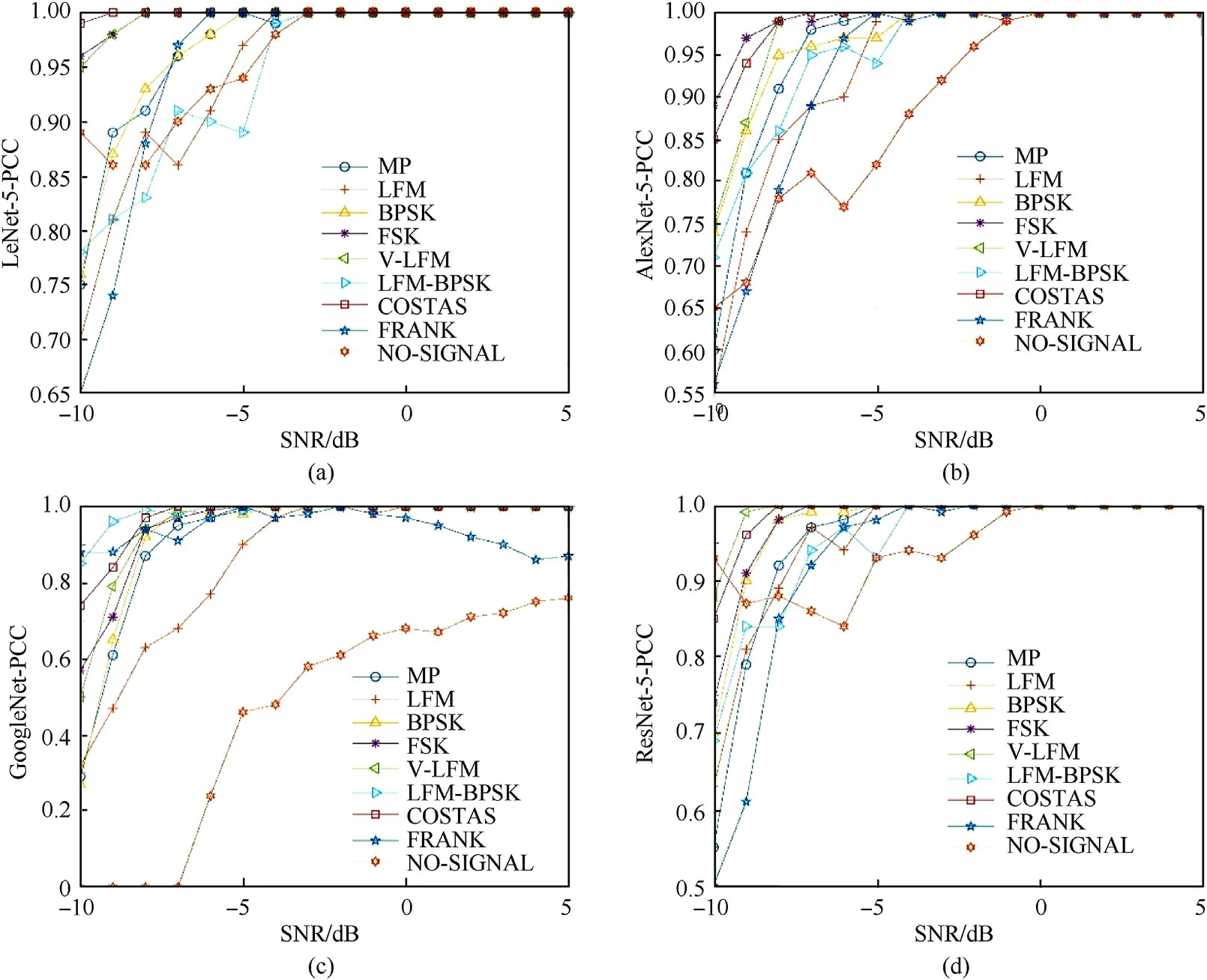
Fig.9.DL-based radar signal PCC.(a) The PCC of LeNet-5.(b) The PCC of AlexNet.(c) The PCC of GoogLeNet.(d) The PCC of ResNet-34.
Fig.9 shows the probability of correct classification(PCC)of the LPI radar signal via NYFR based on DL.Fig.9(a)-(d) respectively show the PCC curves of LPI radar signals based on LeNet-5,AlexNet,GoogLeNet,and ResNet-34.It can be found that as the SNR increases,the PCC of each classifier also increases,they eventually are close to 100%,and the PCC of GoogLeNet is slightly weaker than the other three.From a partial point of view,no signal,LFM,and LFM/BPSK signals perform slightly weaker at low SNRs,while frequencycoded signals such as BFSK and Costas perform better.This is because for low SNRs,the TFI may be ambiguous and the phaseencoded signal is not easily distinguishable.The no signal type has strong randomness,thereby its TFIs are easy to be misjudged as other types with low SNRs.However,the frequency-coded signal is different.As far as the signal itself is concerned,the performance in the TFI changes drastically over time,so the PCC caused will be significantly higher than that of the phase-encoded signal.
Moreover,the performance of the DL-based LPI radar signal intra-pulse modulation type recognition proposed in this paper is excellent at low SNRs.However,in some classifiers such as AlexNet and GoogLeNet at high SNRs,recognition performance Frank decreases,and it is misjudged as a BPSK signal.This is because the convolution calculation is locally converged,thus,similar characteristics have led to misjudgments.Moreover,the reasons for the fluctuations in Fig.9 (b)-(c) also include the adaptability of STFT technology to DL and the insignificant contrast of Frank at high SNRs.As the number of network layers increases in the training sample,the gradient gradually disappears,which makes the overfitting situation appear.Therefore,many factors should be taken into account in the ordinary application process,especially the volatile environment such as a battlefield electromagnetic environment.It is worth considering if the completion is more efficient at less cost.However,in the case of a small number of network layers,due to fewer convolution calculations,the network may not be easy to converge.Therefore,it is necessary to comprehensively consider and select the appropriate network to be suitable for different electromagnetic environments.
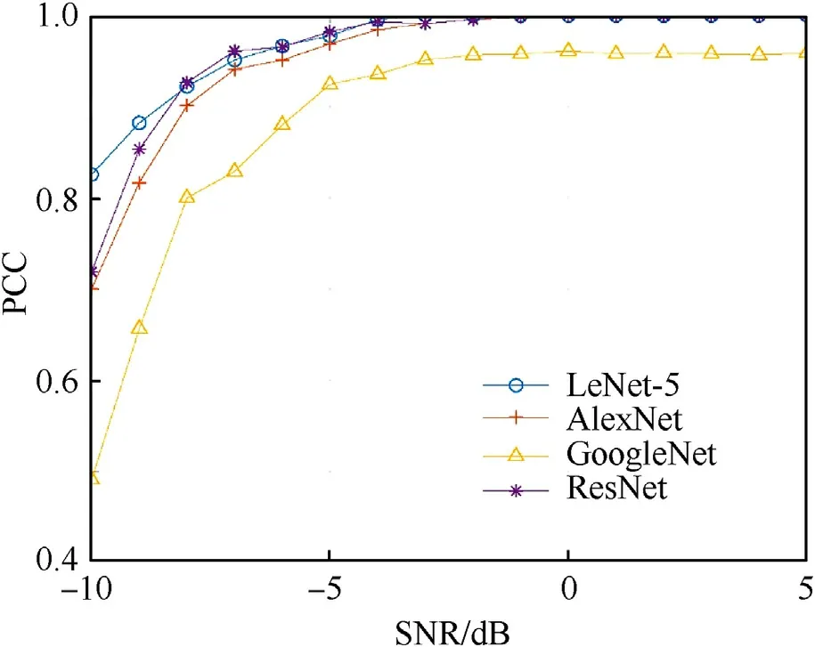
Fig.10.Comparison of average PCC of four DL algorithms.
Fig.10 shows the comparison of the average recognition probabilities of the four classifiers.Horizontally,PCC tends to increase with the increase of SNR.When the SNR is -10 dB,the PCC of LeNet-5 is significantly higher than the three DL algorithms of AlexNet,GoogLeNet,and ResNet-34,and the PCC is bigger than 80%.When SNR is greater than -5 dB,the four DL algorithms PCC all exceed 90%.Therefore,it is reasonable to believe that CNN has certain effectiveness in modulation type identification of nine radar signals,including MP,LFM,BPSK,V,LFM/BPSK,BFSK,Costas,Frank,and no signal.When the SNR is-3 dB,the PCC of LeNet-5,AlexNet ResNet-34 is almost 100%.On the contrary,GoogLeNet tends to gradually stabilize,but it is difficult to reach 100%.Which is consistent with the previous analysis.Due to the existence of overfitting and gradient disappearance,PCC may not necessarily increase with the increase in the number of network layers.It is worth mentioning that ResNet -34 has been performing well because of its shortcut connection,which avoids the situation where the more network layers,the gradient disappears.
Table 3 shows the confusion matrix of the four DL algorithms LeNet-5,AlexNet,GoogLeNet,and ResNet-34 at SNR of-8 dB.It can be found that the four types of modulations,BPSK,V-Shaped,LFM/BPSK,Costas,and Frank,perform well,all above 90.The no signal performance is very poor,especially for GoogLeNet,the recognition rate is 0,which shows that for the aliased no signal type,the DL classifier is not fully trained,and no signal itself uncertainty is also a huge challenge.The performance of LFM and BFSK signals is poor.This is mainly because the TFIs of LFM and FSK signals are very similar at low SNR,the probability of being misjudged as the other party will increase.But as the SNR increases,the differences will become obvious,and PCC will also increase.MP signal performance is moderate.
The calculation time (CT) of the four classifiers is shown in Table 4 in the Python environment built by GPU under NVIDIA GeForce GTX 1650.It can be known that the CT of the four classifiers increases as the number of network layers increases,which is consistent with our cognition.The training period of each classifier is 100 epochs.While LeNet-5 only needs 6 s per epochs,this is because Lenet-5 has only two layers of convolution and two layers of pooling.Also,the size of the convolution kernel is only 5*5,and the size of the pooling layer is only 2*2.This does not mean that LeNet-5 is superior to ResNet-34,but that for different images,the classification performance does not necessarily increase as the number of network layers increases.The simpler the classification situation,often only a simple network is required for training.However,simple network changes are sometimes unstable,especially non-convergence caused by too few convolutional layers.In this case,a deeper network is needed,such as for RGB threechannel images.Therefore,for different images,different networks should be used for training to obtain the best performance.
4.3.Compared with other recognition technologies
Based on considering NYFR,the signal itself adds LO modulation information,SFM is set in this paper.As shown in Eq.(15),the MP signal folding frequency adds cosine modulation with amplitudekHωθto the fixed frequency ω0,and the signal itself after NYFR folding can be regarded as a complex modulation signal.Literature[25-29] did relevant recognition processing for LPI radar signals,but they all considered the signal reception problem.Put them in the same NYFR signal receiving environment,and the PCC comparison is shown in Fig.11.
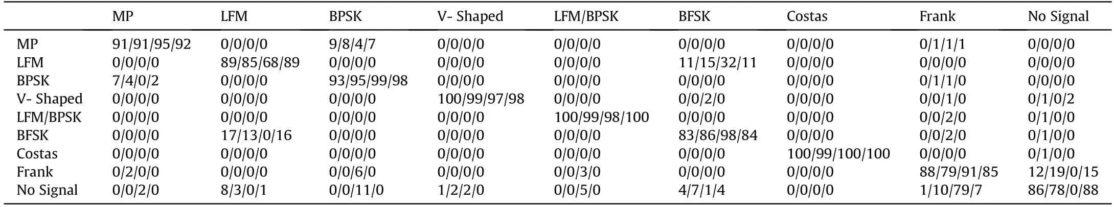
Table 3 Confusion matrix at SNR of -8 dB.
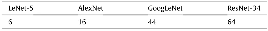
Table 4 CT (s)/Epochs.
Through simulation experiments,the experimental results are shown in Fig.11.It can be found that the DL algorithm[25-27]is far superior to the feature-based recognition algorithm[28]in the field of recognition processing.This is mainly because,in the process of feature extraction,there may be reasons such as less extraction,insufficient representation,and introduction of feature errors.The DL algorithm is directly processed for the image,which contains the process of feature representation and recognition.Moreover,it can be found that the algorithm PCC proposed in this paper is superior to other algorithms.The size of the image PCC often depends on the true restoration of the original image to the LPI radar signal.Therefore,in many cases,the preprocessing of the image may not completely characterize the signal under different SNRs.To identify signals more accurately,factors such as network structure and TFA conversion performance should be considered comprehensively.
LPI radar signals recognition via NYFR based on the DL algorithm,whether from the perspective of signal reception or the perspective of recognition accuracy,the algorithm proposed in this paper is outstanding.However,the NYFR structure still has certain limitations.For example,after the 8.2 GHz MP signal and the 10.2 GHz MP signal simultaneously are folded by NYFR,they represent the same signal,and further processing is required at this time.Moreover,the hardware implementation performance of NYFR is poor,which requires the continuous efforts of follow-up researchers.The DL also has certain limitations,such as the need for a long training period,which is not conducive to the real-time combat environment.
5.Conclusion
This paper proposes a DL-based LPI radar signal analysis and recognition method via NYFR architecture.First,the structure of NYFR radar signal receiving is studied,including signal noise analysis received by NYFR and signal time domain,frequency domain,and time-frequency domain analysis.Secondly,combined with the folding characteristics of NYFR,the folded signal is converted into a TFI through the STFT algorithm.Subsequently,the modulation type recognition method of LPI radar signal based on the DL algorithm is proposed,including LeNet-5,AlexNet,GoogLeNet,and ResNet.Finally,through simulation verification,the PCC can reach more than 90% when SNR is greater than -8 dB.When SNR is greater than -3 dB,nine modulation types of radar signals can be identified simultaneously.Moreover,we also discussed the limitations of NYFR and DL algorithms.In future work,we will study the problem of signal recognition in the case of small samples or multi-component through further research on NYFR and deeper DL structures,such as reinforcement learning.Also,we will start to study NYFR-based NZ domain estimation and NYFRbased high-precision parameter estimation technology.
Declaration of competing interest
The authors declare that they have no known competing financial interests or personal relationships that could have appeared to influence the work reported in this paper.
Acknowledgments
This work was supported by the National Defence Pre-research Foundation of China.
杂志排行

Defence Technology的其它文章
- Experimental and numerical analysis on suitability of S-Glass-Carbon fiber reinforced polymer composites for submarine hull
- Damage response of conventionally reinforced two-way spanning concrete slab under eccentric impacting drop weight loading
- Analysis and design for the comprehensive ballistic and blast resistance of polyurea-coated steel plate
- Positive effects of PVP in MIC: Preparation and characterization of Al-Core heterojunction fibers
- Flight parameter calculation method of multi-projectiles using temporal and spatial information constraint
- Numerical simulation of drop weight impact sensitivity evaluation criteria for pressed PBXs