Flight parameter calculation method of multi-projectiles using temporal and spatial information constraint
2023-01-18HanshanLiXiaoqianZhang
Han-shan Li,Xiao-qian Zhang
School of Electronic and Information Engineering,Xi'an Technological University,Xi'an,710021,China
Keywords:Six detection screen array Multi-projectile Recognition and matching Temporal and spatial information constraint Wavelet transform
ABSTRACT The dynamic parameters of multiple projectiles that are fired using multi-barrel weapons in highfrequency continuous firing modes are important indicators to measure the performance of these weapons.The characteristics of multiple projectiles are high randomness and large numbers launched in a short period of time,making it very difficult to obtain the real dispersion parameters of the projectiles due to the occlusion or coincidence of multiple projectiles.Using six intersecting-screen testing system,in this paper,we propose an association recognition and matching algorithm of multiple projectiles using a temporal and spatial information constraint mechanism.We extract the output signal from each detection screen and then use the wavelet transform to process the output signal.We present a method to identify and extract the time values on which the projectiles pass through the detection screens using the wavelet transform modulus maximum theory.We then use the correlation of the output signals of three parallel detection screens to establish a correlation coefficient recognition constraint function for the multiple projectiles.Based on the premise of linear projectile motion,we establish a temporal and spatial constraint matching model using the projectile's position coordinates in each detection screen and the projectile's time constraints within the multiple intersecting-screen geometry.We then determine the time values of the multiple projectiles in each detection screen using an iterative search cycle registration,and finally obtain the flight parameters for the multiple projectiles in the presence of uncertainty.The proposed method and algorithm were verified experimentally and can solve the problem of uncertainty in projectiles flight parameter under different multiple projectile firing states.
1.Introduction
With the development of high-frequency multi-barrel continuous-firing weapons (HFMBCFWs),the spatial dispersion density,hit probability and target damage efficiency of the multiple projectiles are important indices for measuring the weapon performance.The technical index of space dispersion of multiple projectiles is particularly important,as it determines the target damage efficiency of the weapon and its overall effectiveness [1].Due to the large number of projectiles fired by HFMBCFWs within a very short period,there are some factors from the weapon firing moment,such as jitter,inconsistent charge quantity and inconsistent bore rotation frequency that cause uncertainties in the projectile flight state,leading to the overlapping or mutual occlusion of multiple projectiles in certain positions.It is very difficult to establish measurement mechanisms of multiple-projectile dispersion parameters under random uncertain dispersion states,and this limits the research and development of smart weapons.In the field of weapons development,there are many forms of ammunition damage.To determine the damage efficiency of different ammunition weapons,the main parameters such as flight velocity and coordinate distribution of multiple projectiles important factors.In particular,the determination of multi-projectile space dispersion parameters for HFMBCFWs needs to be accurate,because these parameters are at the core of improving combat efficiency of these weapons.The determination of these parameters is thus one of the research hotspots in the global weapons’ research.
There are many types of HFMBCFWs,such as the metal storm weapons system[2],the type 730 30 mm close-quarters cannon[3],the HPJ-11 11-barrel 30 mm naval gun [4],the AK-630 close-quarters cannon[5],etc.The multiple projectiles fired by these weapons form a multi-layer projectile curtain in space,which continuously damages the attacking targets or the bridge buildings within a very short time span,with the purpose of inflicting high damage to the target.HFMBCFWs have two main characteristics.First,a multibarrel weapon is rotated and fired at high frequency,which makes the firing projectiles form a multi-layer projectiles-curtain with different dispersion states in space.The number of projectiles is large,the time interval between projectile releases is short,and the density of projectiles is large,while the frequency of firing can reach more than 2000 rounds per minute.Second,the stability of the gun barrel during rotation is inconsistent,which introduces uncertainty to the dispersion state of the fired projectiles in space.Because of the above reasons,it is difficult to efficiently capture and recognize the flight parameters of multiple projectiles using existing test methods.For measurement of the spatial position and velocity parameters of flying projectiles,the existing non-contact photoelectric detection methods mainly include multi-light screen intersection test methods,double-linear array CCD intersection test methods,laser detection screen targets,etc.In Ref.[6],a projectile flight parameter measurement model and its test precision analysis based on a parabolic ballistic was studied,and the general measurement model of a six screen array testing system was established.A three-dimensional coordinate measurement method of projectile proximity explosion position was proposed in Ref.[7];and the coordinate precision analysis under the influence of multiple factors was explored.A density test technology for the fired projectiles based on a large-area dual-source laser light screen was studied in Ref.[8].In Ref.[9],two kinds of six-light screen array measurement methods based on a large detection surface were studied.A double-linear array CCD intersection measurement model was put forward in Ref.[10].A measurement error analysis of a linear CCD testing system in full field of view was studied in Ref.[11].
These methods can be used to obtain the position and velocity of multiple projectiles fired by single- or multi-barrel weapons in sequence,and can also recognize the projectile signals effectively using certain sequence rules.However,HFMBCFWs are different from conventional weapons,these are mainly reflected in two aspects.First,the dispersion state of multi-projectile is irregular,so there may be overlaps due to multiple projectiles arriving at the same detection screen plane at the same time.For current sensors,the information obtained from these multiple projectiles arriving at same position at the same time is regarded as a single projectile signal,so it is difficult to distinguish the information corresponding to each of the multiple projectiles [12,13].Second,the inherent characteristics of multi-barrel weapon firing make the flight attitudes of the multiple projectiles different,and it is possible that projectiles fired earlier are overtaken by others fired later in the sequence.Therefore,the continuous characteristics of the collected projectile signals in time may not reflect the real sequence of continuously-fired projectiles;as the space parameters of each projectile are calculated from the time values of the projectile signals collected by the sensors,the results may be wrong.
Some solutions to this problem have been proposed by researchers.Examples include the divided screen array measurement method of projectile-curtain parameters for multi-barrel volleyed weapons,this method is effective only when the firing frequency is fixed and the fired projectile signals can be clearly distinguished in time [14].A static explosion warhead fragment velocity test method based on an active screen array testing system was studied in Ref.[15].The testing system mainly involved establishing a velocity recognition method for the multiple warhead fragments.However,the testing system could not ascertain a specific position calculation method of warhead fragments.In Ref.[16],the density test method for weapons with projectile sequences and projectile curtains was studied based on a linear CCD intersection testing system.This method places strict requirements on the coordinate systems of the two linear CCD intersection screen planes and on firing multiple projectiles.At the same time,the correlated features of multiple-projectile imaging position consistency between the two screen planes are relatively few,and the probability of missing measurements is relatively higher,which does meet the current requirements of HFMBCFWs.
In order to solve the problem of testing the flight parameters of multiple projectiles with uncertainties introduced by HFMBCFWs,in this paper,a photoelectric detection target with high sensitivity and a large field of view is used as the core projectile detection sensor,and a test configuration with multiple photoelectric detection target arrays in an intersected arrangement is established.A temporally- and spatially-constrained correlation recognition and matching method for multiple projectiles with uncertain states is studied using the multiple detection-screen array configuration.
2.Projectile flight parameter measuring mechanism based on the intersection of six photoelectric detection targets
The spatial geometric relationship of the six intersecting-screen testing system is shown in Fig.1,M1- M6are the detection screens of the photoelectric detection target.When a projectile passes through the six detection screens consecutively,each detection screen outputs a projectile sequence signal.
The initial moment at which the projectile passes through the detection screen is determined through processing the instantaneous change signal.The detection screen of the photoelectric detection target is shown in Fig.2.The photoelectric detection target uses an array photoelectric detector with high sensitivity and low noise to capture the high-velocity projectile signal.A slit aperture is designed and used in the optical system of the photoelectric detection target.To detect and capture projectile signals,a fan-shaped detection screen is formed in space from the position of the photoelectric detection receiver through the optical lens [18].The field of view of the photoelectric detection target is determined by the optical lens,the length of the slit aperture,and the length of the photosensitive surface of the array photoelectric detector.In this paper,we study recognition,matching and calculation methods for the uncertain flight state of multiple projectiles passing a target intersection testing system using multiple such photoelectric detection screens.
Fig.1.Schematic diagram of six intersecting-screen testing system.
Fig.2.Schematic diagram of detection screen of photoelectric detection target.
We denote tikas the starting time of each detection screen in response to the projectile detection,i=1,2,…,6 as the number of the detection screen,k=1,2,…,n is the number of the projectile passing through the i-th detection screen,and n is the number of projectiles fired by the HFMBCFW.The flight parameters of a projectile can be calculated using the geometric relationship of the six detection screens and the time values at which the projectiles pass through each detection screen.In the testing system,the photoelectric detection target is mainly used to measure the flight parameters of projectiles passing through the detection screens with the aid of a photoelectric detection sensor[17].Through its optical light path,the detection area formed is a fan-shaped detection screen;when a projectile passes through it,an instantaneous change in the light signal is caused.The photoelectric detector of the target captures the instantaneous change in the light signal,through an amplification and conditioning circuit.
The detection array of the six intersecting-screen testing system is designed as multiple detection screens that are pairwise-parallel.M1and M4are parallel to each other and perpendicular to the oz axis;the distance between M1and M4is S,and is called the target distance of the testing system.M2and M5are perpendicular to the xoz plane and the intersection angles with M1and M4respectively are both α.M3and M6are perpendicular to the yoz plane and the angles with M1and M4respectively are both β.We denote the moments at which the projectile passes through the detection screens M1~M6as (t11~t1n),…,(ti1~tin),…,(t61~t6n),where i=1,2,…,6 refers to the corresponding detection screen Mi,n as the number of fired projectiles,and tikis the moment at which the k-th projectile passes through the detection screen Mi.o1o2is the actual flight direction of the projectile,γkand θkare the pitch and azimuth angles of the k-th projectile,respectively.
The calculation function of the flight parameters of the k-th projectile is derived according to the spatial geometry structure of Fig.1 and the time values at which the k-th projectile passes through six detection screens,where
According to Eq.(1),in order to obtain the flight parameters of the continuously fired projectiles,it is necessary to determine the moments at which the n projectiles pass through each detection screen.Since the projectiles are in an uncertain state during flight,there may be multiple projectiles arriving at the same detection screen simultaneously.When this occurs,there is only one peak signal in the photoelectric conversion circuit of the photoelectric detection target.Taking the detection screens M1and M2as an example,as shown in Fig.3.
Fig.3.Schematic diagram of projectiles al and aj arriving at detection screen M1 simultaneously.
In Fig.3,projectiles aland ajarrive at the detection screen M1at the same time.The time values of the projectiles aland ajare t1l=t2j,where t11is the time at which the first projectile arrives at detection screen M1.As shown that in Fig.3(a),when t=t1l=t2j,multiple projectiles arrive at the same detection screen at the same time,resulting in a signal peak superposition for multiple projectiles,so the peak signal at this moment is greater than the peak signal of a single projectile.Similarly,multiple projectiles are arriving at the same time at detection screens M2or M3.For the detection screens M4,M5and M6,because their arrangement is similar to that of M1,M2and M3respectively,and are correspondingly parallel,the corresponding output signals are basically similar to those of M1,M2and M3.Continuously fired multiple projectiles arriving the same detection screen at the same time are in random and uncertain states,so a new recognition and matching model must be established.From the geometric configurations of Figs.1 and 3,although multiple projectiles may arrive at the same detection screen at the same time,due to the intersection angles of the screens,before or after this moment the multiple projectiles must follow a certain sequence through other detection screens.The corresponding output waveform is shown in Fig.3(b).Based on the multiple projectile signals collected by the six photoelectric detection targets,in this paper we propose the method of wavelet filtering and wavelet transform modulus maximum to determine the moment at which the projectile signals of the detection screen are output.
3.Filtering processing and starting time extraction of multiple-projectile signals
We assume that the n projectile signals collected by any photoelectric detection target unit are y(t),where
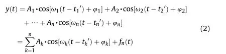
In Eq.(2),Akis the maximum peak value of the k-th projectile signal output by any detection screen,ωkand φkare the frequency and phase of the signal,and tkis the time difference between the peak time of the projectile signal and the acquisition start time in any detection screen.fn(t) is the output signal of the detection screen containing noise.
According to (2),the signal with noise y(t) can be transformed using the wavelet transform [19],where
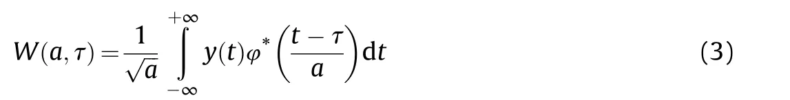
In Eq.(3),a is the scale factor,τ is the time shift factor,andis the conjugate function of the wavelet mother function φ(t).The discretization of signal y(t)is expressed as y(n'),where n'is selected as the discrete point of signal sampling.After orthogonal wavelet decomposition,the wavelet scale coefficient bi',j'and wavelet coefficient ci',j'are obtained.The wavelet reconstruction function is then expressed as:

In (4),h(j'-2n') is the low-pass filter coefficient,which acts on the signal and yields the low frequency smooth signal Ki';g(j'-2n')is the high-pass filter coefficient,which acts on the signal and yields the high frequency details signal Gi'and i' is the number of wavelet decomposition layers (i'=1,2,3,…).Depending on the characteristics of the signals collected from the multiple projectiles,in the algorithm,the output signal of the detection screen is decomposed into 6 layers using the Daubechies wavelet [20,21].Through different scale signal adjustments,the 6th layer low frequency smooth signal K6is observed.We denote K6as 0,the reconstructed signals G1-G6are divided from the 1-6 layer details signal,and the high frequency components of the output signal of detection screen are obtained.
In order to eliminate the high-frequency components of the detection screen's output signal,we denote wi',j'as the signal's wavelet coefficients,and is divide them into two parts,where one is formed by the wavelet coefficients yi',j'representing the projectile signal and the other part is formed by the wavelet coefficients fi',j',representing the noise signal,where wi',j'=yi',j'+fi',j'.The wavelet threshold method is used to remove the noise signal.The Daubechies wavelet basis is used to decompose into one layer,and the noise signal is transformed into the wavelet domain using an orthogonal discrete wavelet,resulting in a set of wavelet coefficientsw(i',j').To apply the fixed threshold,assuming the threshold value is ε,if |w|>ε,the signal characteristics are retained,while if|w|≤ε,the signal characteristics are discarded and w=0.To be able to extract the projectile information,the basic requirement of the fixed threshold function is that the signal-to-noise needs to be greater than 1.5,so the value of ε is 1.5 times the average value of the noise signal,that is:ε=1.5Eψ,where Eψis the average value of the noise signal.
The fixed threshold function is used to obtain an estimation w'(i',j')of the original signal wavelet coefficient from w(i',j'),so we try to make|w'(i',j')-w(i',j')|as small as possible.Then,w'(i',j')is used for wavelet reconstruction,the denoised estimation signal y'(t) is obtained,and y'(t) is the filtered signal containing the projectile information.
Based on the obtained estimated projectile signal y'(t) of the detection screen,it is assumed that y'(t)∈L2(R).The smoothing function is [22]:

If the singularity of y'(t) at the point t0can be described using the Lipschitz exponent[23],we denote k'as a non-negative integer,where k' ≤σ ≤k'+1.If there are two constants M andu0>0,and k'-order Taylor polynomials,make any u ≤u0,where

If(6)is satisfied,if σ is the Lipschitz index and the output signal y'(t)has a singular point at moment t0,then we call σ the Lipschitz index of the output signal y'(t) at t0.The higher the order of the derivative of y'(t) at t0,the larger the corresponding σ,and the smoother the projectile signal is.If the Lipschitz index of y'(t)at t0is less than 1,namely,σ<1,then y'(t) exist singular at t0.
Assuming δ(t) is a Gaussian function,the wavelet φ(t) has k'-order vanishing moments,and the k'-order is differentiable,where k'is a positive integer and σ ≤k',there is a constant M in the neighborhood of t0,so that the wavelet transform of the projectile signal satisfies:

It can be seen from(7)that the singular points of the projectile signal are distributed on the modulus extreme value line of the signal wavelet transform,so the Lipschitz index is less than 1,i.e.σ<1,and the projectile mutation signal is a singularity,so the Lipschitz index is more than 0,i.e.σ>0.Therefore,the wavelet transform is used to find the singularities of the projectile signal.The discrete dyadic wavelet transform is used in (7),which is changed into:

In(8),m' is a binary scale parameter,while t is a discrete value.When the projectile passes through the detection screen,the Lipschitz index of the output signal has σ>0,so the wavelet transform modulus maximum value becomes larger as m'increases.Therefore,the singular point of the collected output signals of the detection screen is located.The wavelet transform can be used for multi-scale analysis,where the singularity point is determined by searching for the maximum value point of the projectile signals [24,25].At the same time,when the discrete wavelet is used to transform the signal,the minimum scale a is selected depending on the characteristics of the projectile signal.
4.Correlation constraint recognition of multiple projectile signals from multiple detection screens
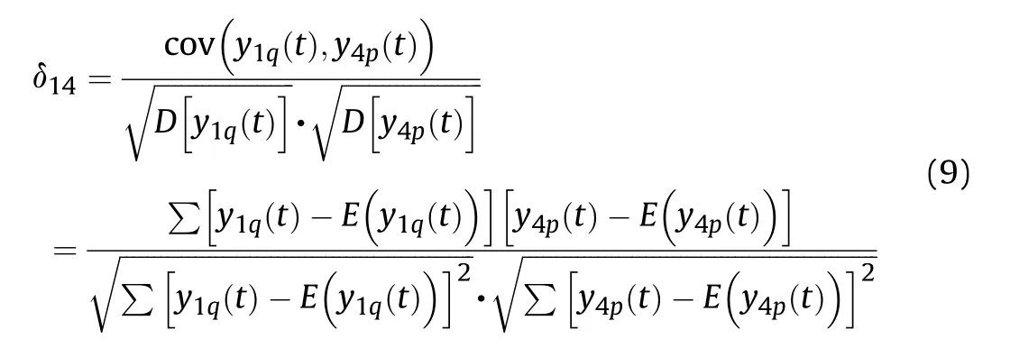
According to the principles of wavelet transform filtering and the time values extracted,because the detection screen is relatively thin,the signal waveforms of the projectiles’passing through each detection screen are similar.From the spatial geometry structure of the detection screen array arrangement in Fig.1,it can be seen that the signal waveforms output by the three parallel detection screens have a strong correlation.The parallel detection screens M1and M4,M2and M5,M3and M6all result in signals correlated each other.The output signal waveform correlations of the three groups of parallel detection screens are used to automatically recognize the attribution relationship of the output signal waveform of the same projectile passing through the parallel detection screens.We denote y1q(t)and y4p(t)as the signal of the q-th projectile passing through the detection screen M1and the signal of the p-th projectile passing through the detection screen M4respectively.Then,their correlation coefficients are:
The correlation coefficient δ25between the detection screens M2and M5,and the correlation coefficient δ36between M3and M6can be obtained in a similar manner.Taking the example of detection screens M1and M4,the specific recognition algorithm is:
1) The multi-channel acquisition module is used to collect the original projectile signal output of the detection screens,and the discrete wavelet transform is used to filter this signal.
2) According to the correlation coefficient function of (9),the corresponding relationship of the output signal of each projectile passing through detection screens M1and M4is analyzed.If the value of δ14is the largest in the correlation coefficient of detection screens M1and M4,then y1q(t) and y4p(t) are related waveforms,and can be regarded as the output signals of the same projectile in screens M1and M4.
3) The wavelet transform modulus maximum time extraction method is used to obtain the time values of the projectile waveforms of y1q(t)and y4p(t).We denote these moments as t1qand t4p,so t1k=t1qand t4k=t4p.
4) The corresponding maximum correlation coefficients δ25and δ36of detection screens M2and M5,M3and M6are found according to the processing methods of steps 1,2 and 3.The corresponding waveforms of the same projectile passing through M2and M5,M3and M6are determined,and the corresponding time values t2kand t5k,t3kand t6kare obtained.Considering the uniform motion rule of the same projectile passing through the detection screen array,we set the constraint v14=v25=v36.
For (1),if we want to obtain each projectile's flight parameters(xk,yk,vk,θk,γk),it is necessary to match each projectile's corresponding time values in the six-screen intersection testing system.Namely,we need to find the time points of the same projectile at the intersection of the detection screens,i.e.the k projectile's time values(t1k,t2k,t3k,t4k,t5k,t6k).From(1),there are eleven unknowns parameters,namely (xk,yk,vk,θk,γk,t1k,t2k,t3k,t4k,t5k,t6k),so we must establish the corresponding constraint equations,and obtain the real information corresponding to each projectile through cyclic iteration matching.
5.Temporal and spatial constraint matching method and algorithm for multiple projectiles
Assuming that there are n projectiles passing through the six detection screens,we denote the corresponding time values as ti1,ti2,…,tin,and yi(t)as the output signal of the i-th detection screen,where i=1,2,…,6.tikis the time value of the k-th projectile passing through the detection screen,where k=1,2,…,n.The temporal and spatial constraint matching method and algorithm for multiple projectiles is as follows:
1) If multiple projectiles do not arrive at the same detection screen simultaneously,and there no projectile signal overlaps or occlusion as the projectiles pass through six detection screens,this means that the firing frequency of the HFMBCFW is relatively low,and the interval between the firing of consecutive projectiles is long.Assuming we collects the signal with information on the k-th projectile,we can then obtain the time value corresponding to the projectile passing through each detection screen.The time values of the k-th projectile extraction are recorded as t1k~t6k,and the corresponding flight parameters(xk,yk,αk,βk,vk) can be calculated directly using (1).The flight parameters of the other projectiles can also be directly calculated in a similar manner.
2) If multiple projectiles arrived at the same detection screen simultaneously or there are more than two projectiles signals when a projectile passes through the detection screens M1and M6,this shows that the firing frequency of the HFMBCFW is high,and the time interval between the firing of consecutive projectiles is very short.As shown in Fig.3,if projectiles aland ajarrive at the detection screen M1at the same time in the ox direction,alwill reach the detection screen M2before aj.If the velocity of ajis greater than that of al,ajwill reach M3before al.Although aland ajarrive at M1at the same time,the order in which the two projectiles reach M2and M3is opposite,so we cannot use the first time value of each detection screen as the first projectile's calculation time.In such cases,it is necessary to establish matching constraints.
Because the distance between the six screens arrays is relatively short,the motion of each projectile passing through the detection screen arrays is regarded as uniform linear motion.According to the extracted time values of the projectile signal,when the time value t11of the first projectile passing through detection screen M1is determined,the coordinates corresponding to M1at t11are A11(x11,y11,z11).For the other projectile signals of M1,the time values are recorded as t12~t1n.The time values of the projectiles passing through the other detection screens in sequence are recorded as t21~t2nt31~t3nt41~t4nt51~t5nt61~t6n,respectively.We denote the coordinate position of the k-thprojectile passing through M1as A1k(x1k, y1k, z1k),and the coordinates of the k-thprojectile passing through the other detection screen are deduced.There are n linear equations for n projectiles passing through the multiple intersecting-screen testing system,and the line of the k-thprojectile passing through the detection screen array is recorded as Ok1Ok2,as shown in Fig.4.
In Fig.4,the k-th projectile passes through the six detection screen intersection points A1kA2kA3kA4kA5k,A6kand the six intersection coordinates form a fixed straight line.This straight line is Ok1Ok2,and the angle between this straight line and the xoz,or the yoz planes is constant for the k-th projectile.From Fig.8,it can be seen that the plane A1kA6k2A6k3is parallel to theyoz plane and A1kA6k2A6k3is parallel to thexoz plane.A2k1~A6k1and A2k3~A6k3are the intersection points of the vertical decomposition of A2k~A6kin planes A1kA6k2A6k3and A1kA6k2A6k3,respectively.A1kA6k2and the oz axis are consistent with the direction,while A1kA6k2is perpendicular to the xoy plane.Assuming A1kis the relative origin,the velocity of thek-th projectile isvk,and the velocity component of the projectile in the ox,oy and oz are vkx,vkyand vkz,respectively.The coordinate positions A2k~A6kof thek-thprojectile passing through the other detection screens can be calculated and recorded as (x2k,y2k,z2k)~(x6k,y6k,z6k).Then
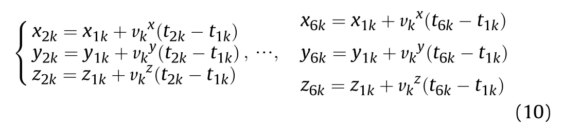
In (10),t1k~t6kare the time values that can be accurately recognized.These values must satisfy the plane geometric equation of the six detection screens.
3) Establish the function of temporal and spatial correlation constraints of the output projectile signals based on the geometric configuration of six the detection screens.
We denote the coefficient related items of the six detection screen plane equations as E,the related items of the site layout testing system as F,the flight parameters of projectile in detection screen M1as Q,where Q=[x1k,y1k,z1k,v1kx,v1ky,v1kz]-1.Equation(11) gives the relation between these elements.In (11),

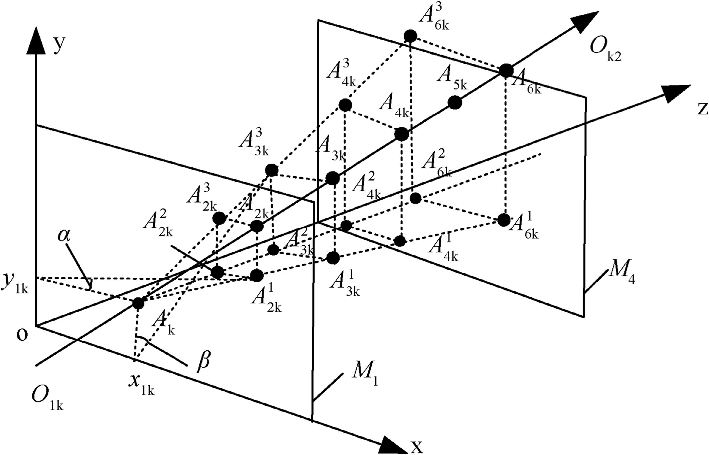
Fig.4.Decomposition diagram of the n-th projectile in thexoy and yoz planes relative to the P1k(x1k,y1k,z1k) position.
If the intersection coordinates of any projectile passing through the six detection screens are A1k~A6k,these coordinates must satisfy (11).According to (1),[x1k,y1k,z1k,v1kx,v1ky,v1kz]-1=[xk,yk,zk,vkx,vky,vkz]-1.In (11),the other parameters can be directly calculated from the design configuration and the layout parameters.
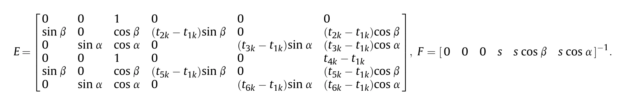
From the constraint functions of (11),combined with the calculation function of (1),we obtain a total of 14 expressions.For the k-th projectile,(xk,yk,vk,θk,γk) and(t1k,t2k,t3k,t4k,t5k,t6k)are the unknown quantities,while the other parameters are all known.Taking t11as the new time value sequence of M1,we set t11'=t11,where t11' is the time value of the first projectile of the new sequence passing through M1.Through the iterative optimization approach and the elimination method,it is judged that the constraint terms are satisfied,and other time values are determined to form a new time value for each projectile passing through the detection screen,marked as tik'.Then,a new sequence of time values t11'~t1n',t21'~t2n',t31'~t3n',t41'~t4n',t51'~t5n',t61'~t6n' is formed.The flight parameters of the n projectiles can be calculated through (1) using the new time value sequence.If there is overlapping or mutual occlusion of multiple projectiles passing through same detection screen,the time value sequences of multiple projectiles passing through the corresponding detection screen are ti1'~ti(n-m)',where m is the number of overlaps or mutual occlusions between the projectiles passing through the same detection screen.These projectiles will have the same time values and also satisfies the constraints of (11).The time values of the multiple projectiles passing through the six detection screens are then determined according to the constraint conditions,and then the flight parameters of the nprojectiles are obtained.
6.Experiment and analysis
6.1.Inherent parameters and output waveform acquisition of the six intersecting-screen testing system
The geometric configuration parameters of the designed six intersecting-screen testing system were set as follows:
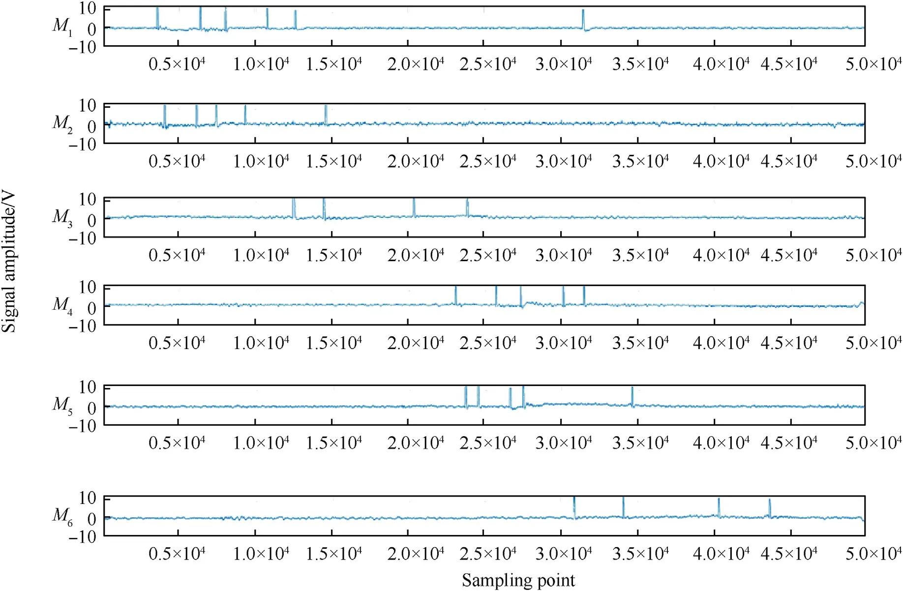
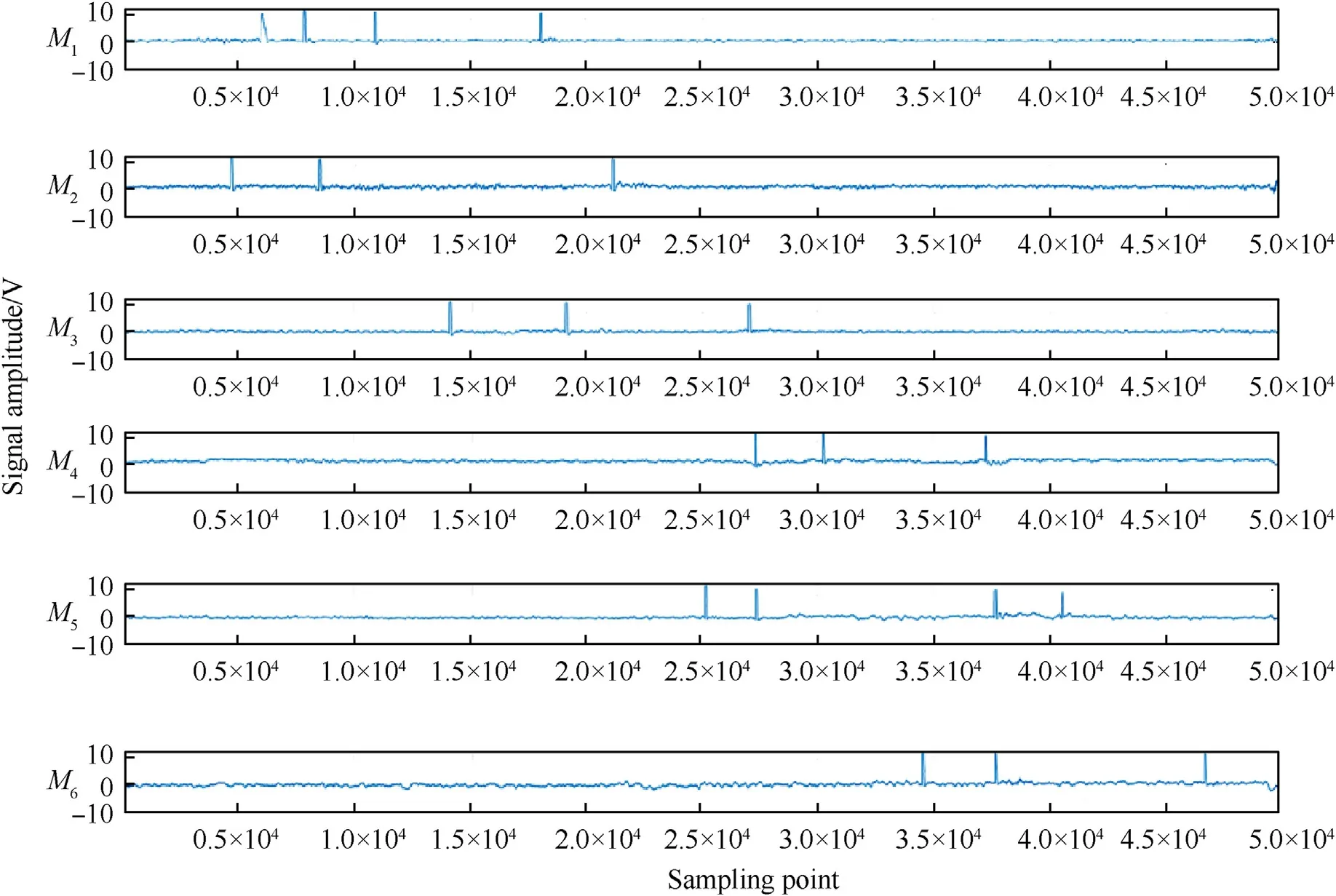
α=.28.5o,β=.23.8o,the optical field of view of the photoelectric detection target was set to 42°,the detection screens M1,M2and M3were integrated into a combined structure,as were M4,M5and M6,and the distance of M1and M4was set to 3.6 m in the test site.The photoelectric detection target was based on visible light bands.The distance between the weapon and detection screen M1was about 10 m,and the range of theoretical flight velocity of the projectile was 680-850 m/s;the output signals of the six detection screens were collected using six synchronous acquisition methods,with a sampling frequency of 4 MHz.The test site is shown in Fig.5.Fig.6 gives the acquisition signals of six continuously fired projectiles based on the test site conditions.
From the waveform of Fig.6,it can be seen that the six output signals collected by each detection screen have a certain regularity,and the first projectile waveform between detection screens M1and M6contains other projectile waveforms,so the time value sequence of the projectiles fired by the weapon at each detection screen cannot be directly determined using the waveform sequences.
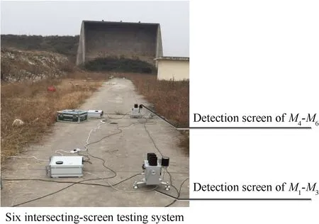
Fig.5.Test site of six intersecting-screen testing system.
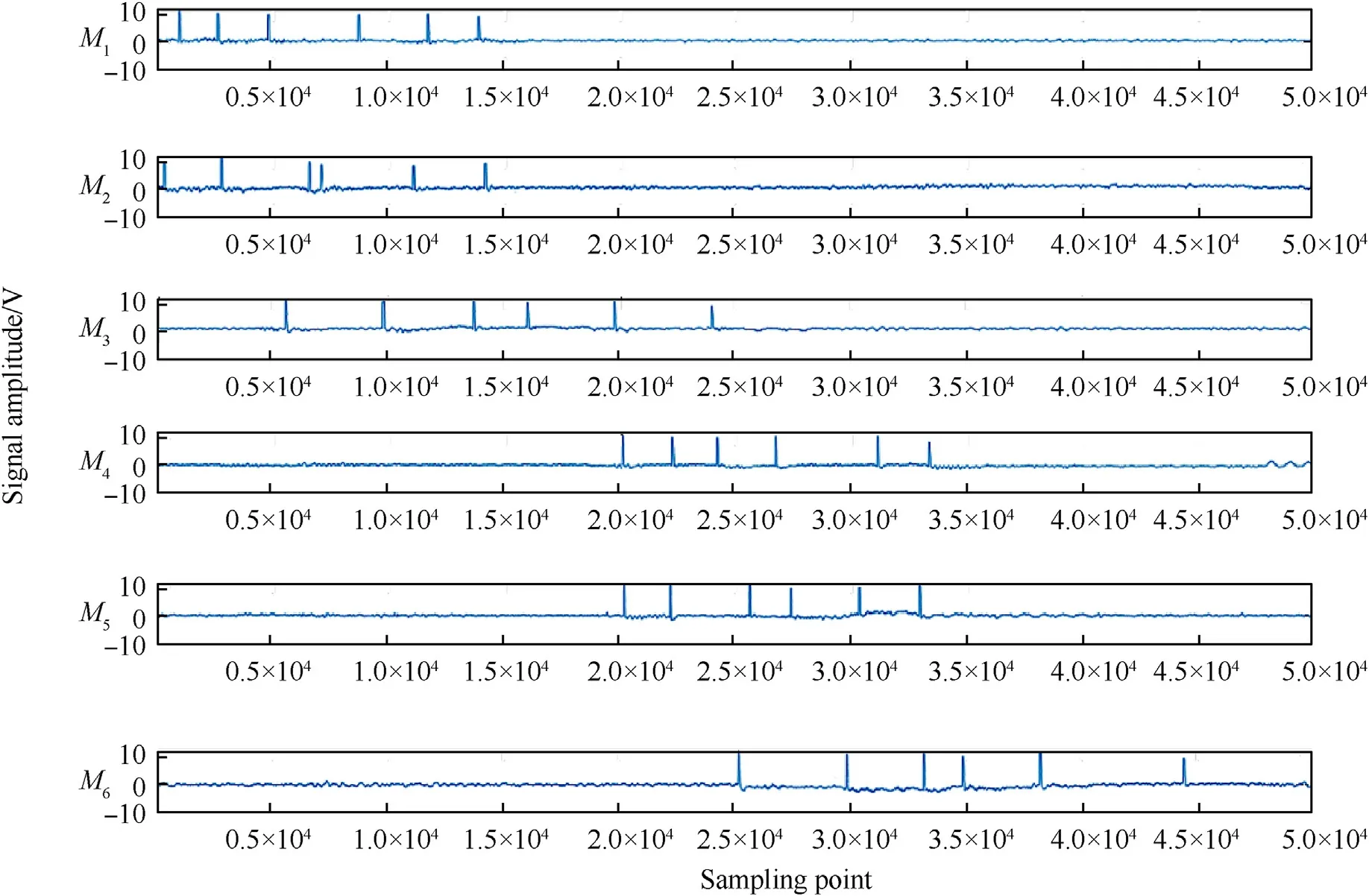
Fig.6.Signals acquired on six continuously fired projectiles.
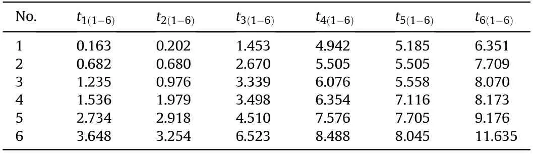
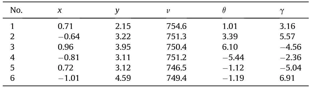
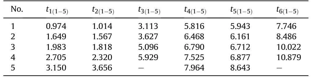
Table 1 Initial time value sequence of six projectiles.
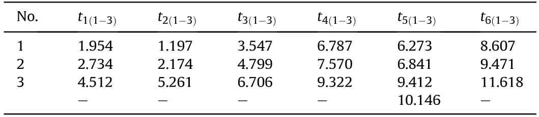
According to the wavelet filtering algorithm and the modulus maxima extraction of initial time values of the projectile signals,we gain the initial time value sequence of each detection screen containing projectile waveforms,as shown in Table 1,among,the unit of time value is ms.
6.2.Recognition of multiple projectile signals’ time sequence
1) The signal waveforms of the same projectile were determined,and the velocity constraint function was established.Taking the example of the parallel detection screens,Fig.7 shows the signal of a projectile passing through the detection screens M1and M4.It was evident that the waveforms of parallel detection screens are similar.Table 2 shows the correlation coefficients for M1and M4.
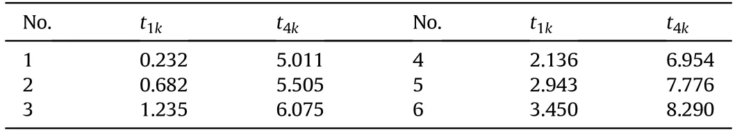
The initial time value sequences of the two detection screens were extracted according to the modulus maximum of the wavelet transform by looking for the maximum value of the correlation coefficient corresponding to the detection screens M1and M4,as shown in Table 3.
The correlation coefficients and flight velocities of projectiles passing through M2and M5,and M3and M6were calculated in a similar manner.
2) The time values of the same projectile passing through six detection screens were determined using the temporal and spatial constraint functions of the projectile signals.The specific constraint function can be obtained using the configuration parameters of six intersecting-screen testing system.
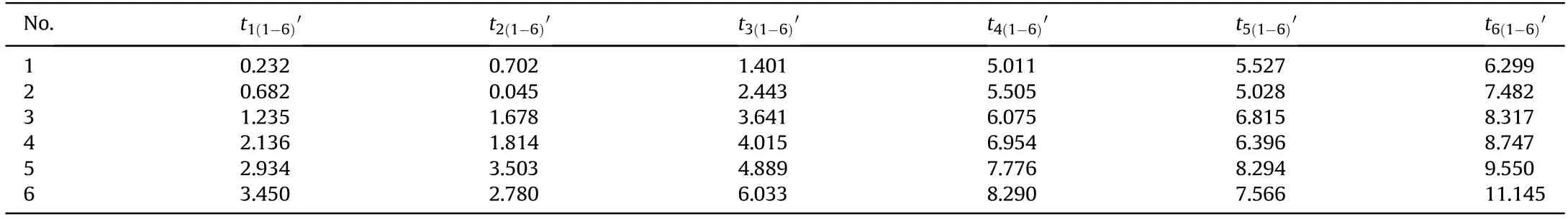
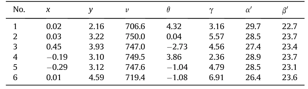
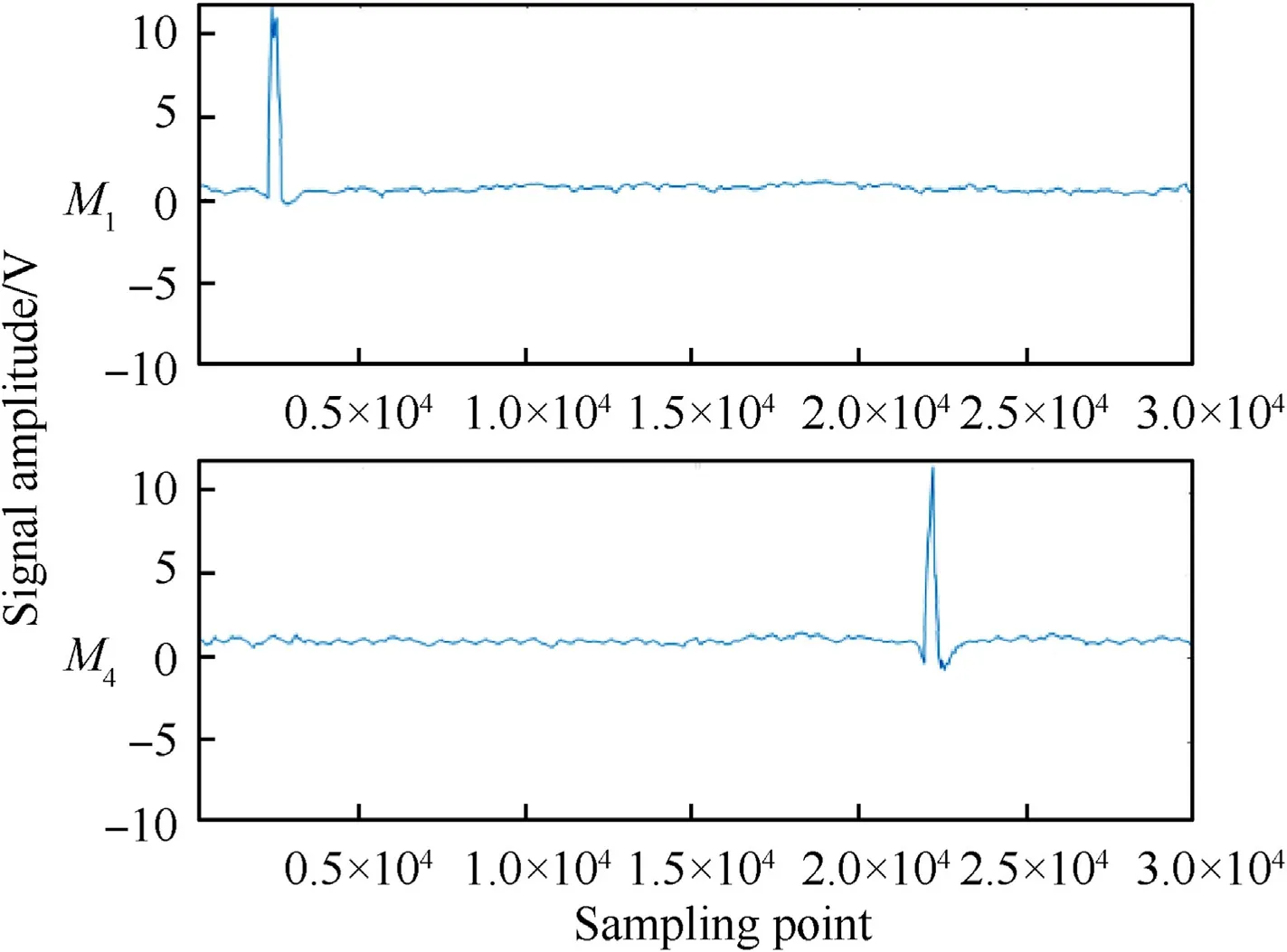
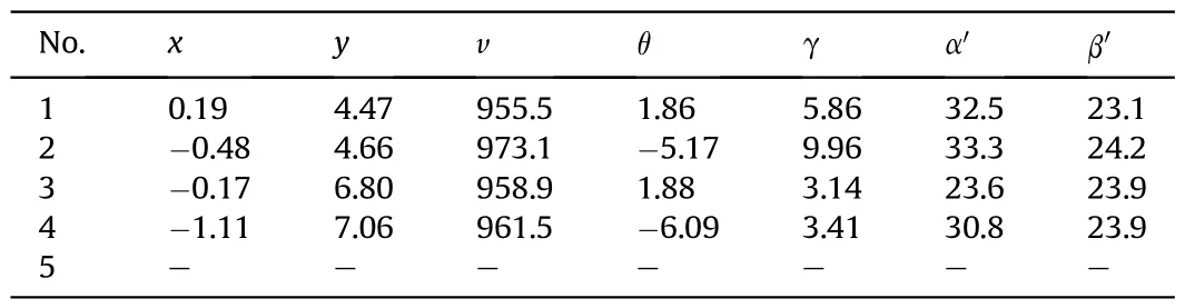
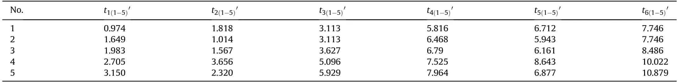
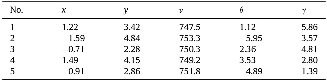
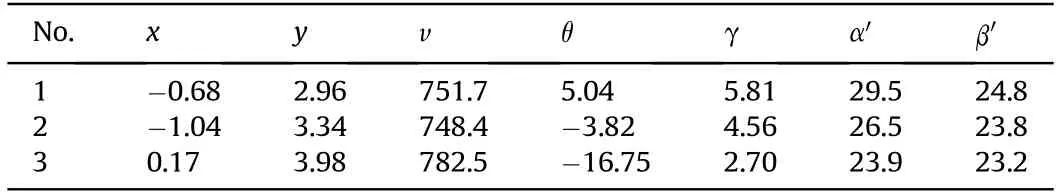
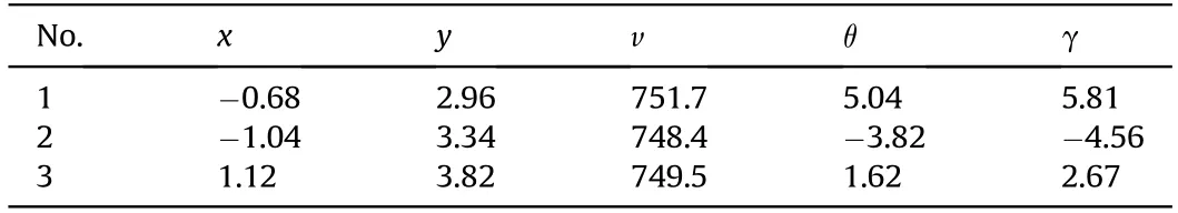
3) The time values of the first projectile passing through the six detection screens are determined.For a group of multiple projectiles arriving at the same time,the first time value (t11) of a projectile passing through M1or the first waveform time(t21)of the projectile signal of M2can be obtained directly from the waveforms of the first or the second channel.If t11 Table 2 Correlation coefficient δ14. Table 3 Initial time value sequences of detection screens M1 and M4. 4) Based on the step(3),the time t21of the second projectile of the group passing through the corresponding detection screen M1or M2is found.The time values corresponding to the constraint functions (10) and (11) are determined using iterative calculation of cyclic search,and are denoted as t21',t32',t42',t52'and t62'.In this manner,the time values of the next projectile passing through the corresponding detection screens M1or M2are found,and the time values of the remaining projectiles passing through each detection screen are obtained using the constraint functions.Table 4 shows the new time value sequence obtained for projectiles passing through each detection screen using the temporal and spatial constraint matching method and processing algorithm of multiple projectile signals.Based on the data of Table 4,the flight parameters of the six projectiles were calculated.Table 5 shows the corresponding results,among,the units of position coordinate and velocity and direction angle of the projectiles are m,m/s and°respectively. From Table 5,it can be seen that the velocity and direction angle of the projectiles are relatively consistent and have astringency well by matching and recognizing the sequence time values,and the calculation results fully reflect the real dispersion state of the continuously fired projectiles.For example,the time values of the first projectile in Table 4 were used to calculate the geometric angle between the detection screens M4and M5,and M4and M6,the corresponding results were α=28.5°,β=23.8°.The calculation result is basically consistent with the design configuration parameters,which verifies the rationality of the matching algorithm. If the time values of the projectiles passing through each detection screen are not matched,the values in Table 1 are used to calculate the projectile flight parameters.The calculation results are shown in Table 6,the intersection angles of M4and M5,as calculated from the time values of the first and sixth projectile are 29.7°and 26.4°respectively,and are different from the fixed intersection angles α of the test system,which does not conform to the six screen plane equations,the measured values of other parameters also vary widely.The results indicate that the initial time sequence are not the real time signal of same projectile passing through the detection screens,so the calculated projectile parameters are wrong. In order to further verify the temporal and spatial information constraint and matching method proposed in this paper,Fig.8 shows the acquisition of five continuously fired projectile signals of another group. It can be seen that there is a false projectile signal at the sampling point 31,602 in the output signal of M1.For the same detection screen,the signal time value at this sampling point is farther than the actual projectile signal time values with a certain frequency continued firing projectile,and the time interval of them is 19 ms,which is far greater than the time value of the actual projectile continued firing frequency.The false signal can be eliminated using the time difference between successively fired projectiles.In addition,the number of output signals of detection screens M3and M6are four,i.e.lower than the actual number of projectiles,while the width of the projectile signal of detection screens M3and M6at sampling point 12,452 and 30,984 respectively,and are slightly larger than the width of the other projectile signals.The results indicate that the probability of multiple projectiles passing through M3and M6at sampling point 12,452 and 30,984 respectively,and are relatively high,i.e.that this time value is the same for two projectiles,which we need to distinguish.The initial time value sequence of the effective projectile signals were determined using wavelet filtering and modulus maximum extraction of the initial time of the output signal.The results are shown in Table 7. Table 4 New time value sequence of the six projectiles. Table 5 Calculation results for six projectiles. Table 6 Calculation results for six projectiles without time value matching. If the flight parameters of the projectile are calculated directly in the order of the time values of Table 7,and corresponding six time values are required to calculate the flight parameters of the projectile according to(1).The flight parameters of the four projectiles were calculated,and the results are shown in Table 8.From Table 8,there is a large difference between the flying velocities of the four projectiles and the theoretical flight velocity of the projectiles.While the intersection angles of M4and M5calculated from the time values of the second projectile is 33.3°,and is also different from the fixed intersection angles α of the test system.The calculated results are not consistent with the dispersion characteristics of the multiple projectiles fired by the same weapon,nor with the six screen plane equations.The results indicate that the data in Table 8 do not truly reflect the real dispersion state of the continuously fired projectile.The time values of the multiple projectiles passing through the detection screens were distinguished and matched using the multiple-projectile signal correlation constraint-based recognition function and the temporal and spatial constraint functions of the multiple detection screen projectile position.The new time value sequences of the projectiles passing through the detection screens were obtained as shown in Table 9,and Table 10 shows the recalculated flight parameters of the projectiles. Fig.7.Single projectile signal in screen M1 and.M4 Fig.8.Acquisition of five continuously-fired projectile. Table 7 Initial time value sequence of five projectile signals. Table 8 Calculation data of five projectiles without time value matching. Table 9 New time value sequence of the five projectiles calculated through matching. Due to the uncertain factors affecting HFMBCFW projectiles,there is a certain probability that multiple projectiles will pass through the same detection screen at the same time.Conventional time value sequences of the detection screen output signals cannot be used to calculate the projectile flight parameters,as this would result in incorrect projectile parameter calculations.It can be seen from Table 10 that the difference between the calculated flight velocity and the ideal flight velocity of the projectile is small.The calculated results reflect the real dispersion state of thecontinuously fired projectile accurately. Table 10 Flight parameters of the five projectiles. Fig.9.Acquisition of three continuously fired projectile signals in the presence of interference. Because of the complex test environment,the testing system using multiple photoelectric detection targets operated in a natural light background.The detection performance of the testing system is greatly influenced by the external environment,so it is inevitable that one or more detection screens of the six intersecting-screen testing system output false projectile signals.Fig.9 shows three projectile signals,among which there is a false signal at sampling point 6253 of detection screen M1.This false signal is close to the real signals of some continuously fired projectiles,but the width of this signal is about three times that of the projectile signal.Based on the characteristic of the projectile signal width,the false signal can be eliminated.However,there are four signals in detection screen M5with basically the same width and amplitude,and there is no large time interval between the signals,so the false signal of M5cannot be eliminated.Similarly,using the projectile signal filtering and start time extraction method based on the wavelet transform,the initial sequence time values of the effective projectile signals were recognized and calculated as shown in Table 11 and in Fig.9.The corresponding flight parameters of the projectiles are shown in Table 12. As there are four signals in detection screen M5but only three projectiles,one signal is a false signal.If the flight parameters of the projectiles are calculated directly according to the time valuesequence of Table 11,the calculation results will be incorrect.According to the calculation results of Table 12,the attitude angle of the projectile were relatively scattered,and the calculated maximum attitude angle of the projectile was 29.5°,which is not consistent with the convergence expected in the flight velocities of a group of projectiles.Meantime,the intersection angles of M4and M5calculated from the time values of the third projectile is also different from the fixed intersection angles α of the test system.The calculated results are not consistent with the six screen plane equations.Therefore,the calculation result was inaccurate.In the same manner,the time values of the multiple projectiles passing through the detection screens were distinguished and matched using the proposed methods.The new time value sequence of the projectiles passing through the detection screens were obtained under conditions of interference as shown in Table 13,and Table 14 are the recalculated projectile flight parameters. Table 11 Initial time value sequence of three projectile signals. Table 12 The three projectile signals without time value matching. The flight parameters of the projectile calculated by matching the new time value sequence of the projectiles in Table 14 were close to the ideal flying velocity of the projectile.Therefore,the results were accurate,reflecting the dispersion state of the real continuously-fired projectiles.In this paper,through three tests of different continuously-fired projectile states,it was effectively verified that the output signal filtering method,the starting time extraction algorithm of the projectile signal,the multiple-projectile signal correlation constraint recognition function and the temporal and spatial constraint function of multiple detection-screen projectile positions proposed in this paper are correct. Table 13 New time value sequence of the three projectiles calculated through matching. Table 14 Flight parameters of the three projectiles. To solve the problem of determining the dispersion parameters of multiple projectiles fired by HFMBCFWs in exterior ballistics,in this paper,we investigated a recognition and matching method and an algorithm for temporal and spatial correlation constraint of multiple-projectile signals in the presence of uncertainties and a method for projectile flight parameter calculation using a multiple intersecting-screen testing system.Through experiments,it is verified that the filtering method of output projectile signal of detection screen,the projectile signal starting time extraction algorithm,the multiple projectile signals’ correlation constraint function,and the temporal and spatial information constraint and matching algorithm are correct and accurate.Factors such as jitter,inconsistent charge quantity and inconsistent bore rotation frequency of the HFMBCFW during firing,lead to the overlapping or mutual occlusion of projectiles.The method proposed this paper successfully solves the problem that in such cases,the flight parameters of each projectile cannot be distinguished.The theoretical method and practical solutions of this paper provide scientific means for obtaining the parameters of HFMBCFWs;they constitute a novel approach for obtaining information about the spatial distribution of explosive warhead fragments of smart ammunition. Funding This work has been supported by Project of the National Natural Science Foundation of China(No.62073256),the Shaanxi Provincial Science and Technology Department (No.2020GY-125) and Xi'an Science and Technology Innovation talent service enterprise project(No.2020KJRC0041). Disclosures The authors declare no conflicts of interest. Declaration of competing interest The authors declare that they have no known competing financial interests or personal relationships that could have appeared to influence the work reported in this paper.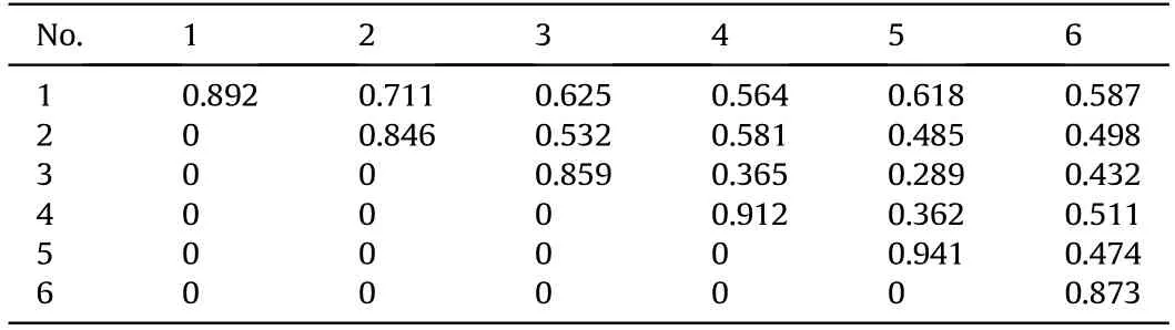

7.Conclusion
杂志排行

Defence Technology的其它文章
- Experimental and numerical analysis on suitability of S-Glass-Carbon fiber reinforced polymer composites for submarine hull
- Damage response of conventionally reinforced two-way spanning concrete slab under eccentric impacting drop weight loading
- Analysis and design for the comprehensive ballistic and blast resistance of polyurea-coated steel plate
- Positive effects of PVP in MIC: Preparation and characterization of Al-Core heterojunction fibers
- Numerical simulation of drop weight impact sensitivity evaluation criteria for pressed PBXs
- Relationships between distribution characteristics of ceramic fragments and anti-penetration performance of ceramic composite bulletproof insert plates