Damage response of conventionally reinforced two-way spanning concrete slab under eccentric impacting drop weight loading
2023-01-18AnsTechErthqukeEngineeringPhScholrMehtAlmPhMohdShriqTechErthqukeEngineeringPhScholr
S.M.Ans,M.Tech (Erthquke Engineering),Ph.D.Scholr ,Meht Alm,Ph.D.,Mohd Shriq,M.Tech (Erthquke Engineering),Ph.D.Scholr
a Department of Civil Engineering,Faculty of Engineering and Technology,Jamia Millia Islamia(A Central University)Accredited with grade A++by NAAC,New Delhi,110 025,Delhi,India
b Department of Civil Engineering,Netaji Subhas University of Technology,(West Campus),New Delhi,110 073,Delhi,India
Keywords:RC slabs Impact loading Eccentric impacts Concrete models Finite element analysis Damage profiles Stresses Peak acceleration Failure modes Damage dissipation energy Cracking Drop-weight locations
ABSTRACT Reinforced concrete (RC) structures are generally designed to carry quasi-static gravity loads through almost indispensable components namely slab,however,it may be subjected to high intense loads induced from the impact of projectiles generated by the tornado,falling construction equipment,and also from accidental explosions during their construction and service lifespan.Impacts due to rock/boulder falls do occur on the structures located especially in hilly areas.Such loadings are not predictable but may cause severe damage to the slab/structure.It stimulates structural engineers and researchers to investigate and understand the dynamic response of RC structures under such impulsive loading.This research work first investigates the performance of 1000 × 1000 × 75 mm3 conventionally reinforced two-way spanning normal strength concrete slab with only tension reinforcement (0.88%) under the concentric impact load (1035 N) using the finite element method based computer code,ABAQUS/Explicit-v.6.15.The impact load is delivered to the centroid of the slab using a solid-steel cylindroconical impactor (drop weight) with a flat nose of diameter 40 mm,having a total mass of 105 kg released from a fixed height of 2500 mm.Two popular concrete constitutive models in ABAQUS namely;Holmquist-Johnson-Cook (HJC) and Concrete Damage Plasticity (CDP),with strain rate effects as per fib MODEL CODE 2010,are used to model the concrete material behavior to impact loading and to simulate the damage to the slab.The slab response using these two models is analyzed and compared with the impact test results.The strain rate effect on the reinforcing steel bars has been incorporated in the analysis using the Malvar and Crawford(1998)approach.A classical elastoplastic kinematic idealization is considered to model the steel impactor and support system.Results reveal that the HJC model gives a little overestimation of peak displacement,maximum acceleration,and damage of the slab while the predictions given by the CDP model are in reasonable agreement with the experimental test results/observations available in the open literature.Following the validation of the numerical model,analyses have been extended to further investigate the damage response of the slab under eccentric impact loadings.In addition to the concentric location(P1)of the impacting device,five locations on a quarter of the slab i.e.,two along the diagonal (P2 &P3),the other two along the mid-span (P4 &P5),and the last one (P6) between P3 and P5,covering the entire slab,are considered.Computational results have been discussed and compared,and the evaluation of the most damaging location(s) of the impact is investigated.It has been found that the most critical location of the impact is not the centroid of the slab but the eccentric one with the eccentricity of 1/6th of the span from the centroid along the mid-span section.
1.Introduction
More often than not,reinforced concrete buildings experience extreme loading caused by direct impact[1,2].Accidental vehicular impact with structures,ice impact on offshore and maritime structures,projectile impact on protective shelters and bridges,impact during the landing of aircraft on the runway,wave impact to the sea wall,and impact-induced by the explosions on structures are some of the examples of impact loading [1,2].The behavior of materials under such loading is usually non-linear with a higher strain rate (≈101to 104) than quasi-static and seismic dynamic loadings [2].Under extreme and impulsive loading events with short durations such as blast and impact,the level of damage could be reparable to collapse.Typically,an elastic analysis is carried out where load factors are applied to the materials to portray dynamic enhancement[2].However,this kind of analysis does not consider the dynamic effects such as strain rate,inertia,and local failure,and therefore is not substantially apt for critical loading conditions,like the aforementioned situations [1,2].
RC slabs are thin plates and their thickness is governed by the limit state of serviceability-deflection criterion [2-7].More often they are singly reinforced with much less reinforcement than their limiting percentage of steel irrespective of their use in interior or exterior portions of the building structures [2,6,7].
Concrete floors of a building quite often suffer from damage caused by the impact of falling rigid objects,explosion-induced flying debris,and vehicle accidents [2].Collapsing load of a floor under gravity may develop a large transient dynamic load on the lower slab.Also,the failure of a slab due to an explosion on it may cause a high-velocity impact on the lower slab.Slabs damaged under impact loading lose their in-plane strength (diaphragm resistance) which alters the lateral load path leading to major damage to the structure under seismic loadings [2].Under such conditions of loading,there are two possibilities of failure of the structure: (1) local failure of the slab,and (2) major failure of the structure [2].
Depending upon the designed specifications of the slab,its local failure generally occurs in the form of concrete scabbing/spalling,cratering,punching,and fracture of the reinforcement along with in-elastic deformation of the slab [2].The formation of the cracks under impact loading reveals the damage mode of the slab.Bending of the slab under such loading triggers the spalling/scabbing of the concrete without penetration of the impacting load [2].
In general,the mode of failure of the slab under impact loading depends upon the applied force,boundary conditions,and other design parameters of the slab[2].Under quasi-static or static loading conditions,it undergoes global bending failure [2].However,under mild impact loading,the supports of the slab experience high stresses,and a flexure-shear failure might replace the bending failure at the supports [1,2].If the same load is applied during a hard impact,the period for stress wave prorogation becomes too short,and the response of the slab under the load is influenced by its local failure[2].The probability of the punching or flexure-shear increases and there may be a combination of different damage modes[2].
2.Objectives
Impact loading analysis has wide applications in civil engineering including crash barrier design,impact resistance structural design against military and terrorist attacks,ship impact resistance design for marine structures and blonder fence design.After the 9/11 aircraft impact incident,there is increased concern about structural response under impact loading also.A high number of slab collapse accidents owing to impact loads have been documented around the world,reported in the open literature[1,2,8-14].More recently Russian invasion of Ukraine raise the concern of researchers and engineers regarding the safety of such structural elements.The objectives of this research work are,primarily:
(1) To investigate the effect of eccentric impact loading on the damage response of the conventionally reinforced two-way spanning square concrete slab with tension reinforcement only.
(2) To establish the severity order of the eccentricity of drop weight impact loading from damage point of view.
3.Review of the latest literature
Response of reinforced concrete beams and slabs under static and less intense dynamic loading conditions have been investigated in recent years through experiments and numerical simulations[7,15-22].Most of the earlier studies conducted under impact loading were having their focus on military and nuclear sectors[1,2,23-25].Recently,a few studies on the dynamic behavior of RC slabs under drop weight impact loading have been performed[24,8,9,26-30].This field of research still seems to be in the developing stage [2,25,31].
Striking of the rolling boulders from the top of the hills due to high-velocity wind,heavy rainfall,shelling from across the border,and seismic movement of the ground,on to the slabs of the nearby structures is quite common[32].Such incidents are more frequent in hilly terrain regions in close proximity to the rivers or water bodies having poor geological conditions/media [32].
The study of the impact resistance of conventionally designed structures has become significantly important in recent years in light of the increase in subversive blasts and projectile impact events [7,33-40].Zineddin and Krauthammer [2] conducted a series of tests to investigate the effect of (1) reinforcements details involving (a) conventional US No.3 steel re-bar mesh on both compression and tension sides,(b)steel mesh at the middle of the slab,(c) welded steel wire fabric mesh on both sides,and (2)drop height,on the damage response of 3353×1524×90 mm3two-way RC slab subjected to constant impact mass load of 2608 kg from heights of 152 mm,305 mm,and 610 mm at the center of the slab.The slab with the steel re-bar mesh on both faces experienced higher peak acceleration and underwent punching shear failure while the slab with steel bar mesh at the middle showed brittle failure mode of concrete.The predominance of the local failure of the slab was observed with increased drop height.In an experimental work by Othman and Marzouk [10],the effect of reinforcement ratio(1,2,and 3%)and reinforcement details(single and double mesh) on the behavior of simply supported 1950 × 1950 × 100 mm3square high strength concrete slabs of strength 80 MPa were investigated under free-fall impact loading.The load was delivered to the slab by dropping an impact mass of 475 kg from a height of 4150 mm at the center.Interesting observations with regards to reinforcement ratio and arrangement were made such as(1)impulse and absorbing the energy of the slab were not significantly influenced with variation in reinforcement arrangement and its ratio,and (2) mode of failure and damage pattern were influenced mainly by the arrangement of the reinforcement(s).Berthet-Rambaud et al.[41] experimentally and numerically studied the concentric impact loading effect on 12,000 × 44,000 × 280 mm3simply supported RC road sheds of concrete compressive strength 32.50 MPa and steel yield strength 500 MPa.The impact load of 450 kg was delivered at the mid-point of the shed from two different heights of 15 and 30 m.Experimental results were compared in terms of maximum deflection and found matching closely with the computed ones.Another experimental and numerical investigation by Xiao et al.[42] revealed that increasing the concrete strength and thickness of conventional RC slab improved its performance against drop mass impact loading,however,the effect of reinforcement ratio was found less significant on the performance of the slab.Jahami et al.[32]performed smallscale drop weight impact tests on 1000 × 500 × 100 mm3simply supported RC slab,and evaluated the maximum deflection and damage pattern.The impact masses of 5 kg,10 kg,and 18 kg were dropped from heights of 600 mm and 1000 mm at the center of the slab.Obvious observations with regard to maximum deflection,acceleration,and cracking were reported i.e.,these values increased with the increase of drop mass and height.Tahmasebinia et al.[43]conducted a series of impact tests to investigate the effect of vertical and lacing shear reinforcements on the performance of 1355×1090×90 mm3RC slabs subjected to drop mass of 635 kg from a height of 5500 mm at the slab center.Results revealed that the slab with shear reinforcement gave better performance than with flexural reinforcement under the similar impact load.Moreover,the influence of vertical shear reinforcement was found more effective than the effect of lacing reinforcement.Recently,Sadraie et al.[1],based on testing and numerical simulation,investigated the performance of 1000 × 1000 × 75 mm3slabs of normal and high strength concrete: (1) without reinforcement,and (2) with single/double reinforcement in the form of (i) steel bar mesh,and(ii) glass fiber-reinforced polymer (GFRP) bar mesh,under drop mass impact loading generated by dropping a conical frustum headed projectile of weight 105 kg from a height of 2500 mm at the slab center.Results showed the slabs with steel bars performed better than with GFRP bars in terms of maximum displacement and damage.Higher reinforcement ratio and use of double reinforcement reduced the maximum displacement.General understanding with regards to compression and tension reinforcements in the slab under quasi-static loading was also found complying under lowvelocity impact loading that higher percentage of tension reinforcement made a better influence on the performance of the slab than with higher compression reinforcement.
In addition to the above researches,a few studies were also done to investigate the performance of RC slabs with (1) glass fiberreinforced polymer (GFRP) re-bar mesh,and (2) carbon fiberreinforced polymer (CFRP) sheets,under concentric impact loading by validating the numerical model with the available testing results in the open literature [25].Dynamic commercial computer codes such as ABAQUS/Explicit,LS-DYNA,and ANSYS AUTODYN were mostly utilized for this purpose [2,7,11,12,44-60].Slabs with the GFRP bars were not found effective to control the damage,attributed to lower stiffness of the GFRP than the conventional steel[1,17,22].On the other hand,the CFRP strengthened slabs gave an outstanding performance in comparison to the conventional steel reinforced concrete slabs under similar impact loading conditions [25,61].
4.Motivation for this research work
Conventional structural design does not include loading from explosion or projectile impact events.Thus few buildings are designed with the requisite resistance against impulsive loadings(blast and impact).Exceptions to this are buildings in petrochemical facilities where explosion/projectile impact hazards exist and high profile buildings such as embassies [7,33-40].Existing literature reveals that impact loading at the centroid of the slab causes the maximum damage and accordingly the loading had been considered irrespective of the boundary conditions,dimensions,andotherdesignparametersoftheslab[1,2,27,31,32,41-43,13,14,62,63].Against this common perception,the damage response of slab under the eccentric impact loading conditions had not been studied and therefore is of considerable interest.Recently a steel bridge collapsed under the impact of a rolling boulder down the slope of a hill without any live load on the bridge located in Himachal Pradesh,a state in the northern part of India(Fig.1),reported in Ref.[64].Interestingly,the hit was not on the mid-span region but eccentric i.e.,around one-third span of the bridge.The collapse of the bridge under the eccentric impact of the boulder is the motivation to consider the eccentric impact loading effect on the RC slab.To cover this research gap,the authors first numerically validated the displacement,peak acceleration,and damage response of 1000 × 1000 × 75 mm3two-way spanning conventionally reinforced concrete slab of normal strength concrete (29.70 MPa) under the concentric (P1) impact loading with the available experimental data and subsequently extended the work by investigating its performance under eccentric loading conditions.Five eccentric drop weight impact points(or locations)to cover the entire slab have been considered: two along the diagonal (P2 and P3),the next two along the mid-span section (P4 and P5),and the last one(P6)between P3 and P5,as shown in Fig.2.It is to be noted that,to study the response of the slab under eccentric impact loadings,the slab has been modelled with the boundary conditions and other design parameters considered in the experimental study by Sadraie et al.[1].
A general-purpose high-fidelity physics-based dynamic computer hydrocode,ABAQUS/Explicit,is employed to simulate the effect of impact loading on the slab.As per the current literature[49,7,59],the most widely used commercial computer code for simulating extreme dynamic loading effects on structures involving high strain rates is ABAQUS.An impact loading problem can be modelled in several ways in this computer code,reported in Ref.[59].In this study,the impact loading effect on the slab is modelled and simulated using the explicit solver technique which solves the equation of motion with increments and modifies the stiffness matrix after each increment of load,and considers the corresponding displacement for geometric non-linearity.The two representative mathematical concrete models in ABAQUS [65]namely;Holmquist-Johnson-Cook (HJC) and Concrete Damage Plasticity (CDP) with strain rate effects are in vogue to predicting the damage of the RC structural elements under impact loading[59,7,66].Therefore,the authors have considered the two models for simulating the concrete plasticity and damage of the slab.Accuracy of these two material models in predicting the damage response of the slab under concentric impact loading is discussed and compared with the available experimental results/observations,and subsequently,the material model giving results close to the experimental ones is adopted for further investigation of the slab under eccentric impact loadings.
5.Research significance
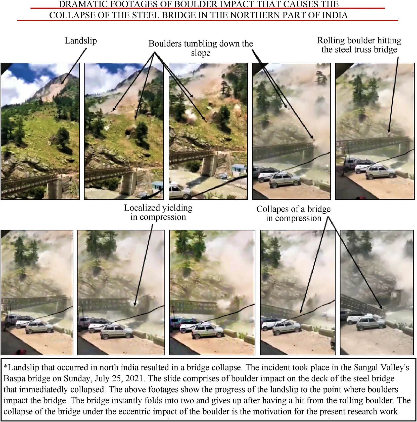
Fig.1.The landslip sent boulders rolling down hills,destroying cars and collapsing a steel truss bridge in the mountainous northern Indian state of Himachal Pradesh [64].
Resilience is the latent requirement of the structure against possible extreme loadings for safety and longevity against damage[1,2,11,52-54].Therefore,it necessitates to assess the response of the structure under such loadings to improve structure design philosophy [11,12,56,57].Understanding of the structure behavior subjected to impact loading is still in its infancy,nonetheless,development in this area is spurred by a wide range of engineering applications such as vehicular collisions with structures,aircraft crash loading on structures,the impact of projectiles,and impact of falling boulder/rock,etc.
This study presents the damage insight of the slab caused by the eccentric impact of a rigid object(drop weight).The findings of this research work are useful to structural engineers as well as the sectional committee for drafting the standard of impact-resistant design of structures.
6.Numerical study (FEM-based)
Highly transient dynamic loadings such as impact and blast,and their equally transient effect on structure or components preclude the investigators to comprehend the instant failure of the building structure in experimental studies and therefore provides motivation to go for numerical simulations under such loadings[59,7,67].Thus,the use of computer dynamic programs is indispensable for problems involving impulsive or impact loadings.In the present work,numerical models have been developed in ABAQUS/Explicit version 6.15 (release 2020) [65] computer code which is based on explicit numerical methods that are suitable for solving problems associated with large deformation subjected to impact,and the computed results are compared with the available experimental ones reported in Ref.[1].
6.1.Finite element (FE) modeling of RC slab under impact load
A total of ten FE models are developed in ABAQUS/Explicit computer code.Four out of ten models are control models i.e.,subjected to concentric(P1)impact loading,and are made with the CDP material model using the maximum seed size of 10 mm,15 mm,20 mm,and 25 mm throughout the models.In addition,one control model is made with the HJC material model using a 10 mm element size.The remaining five models are subjected to eccentric(P2-P6) impact loadings and are explicitly meshed with a 10 mm seed size which is selected based on the results of the mesh convergence test(sensitivity analysis)discussed in section 6.3.Each model consists of a concrete slab with conventional steel re-bars of 8 mm diameter at 100 mm c/c in both directions on tension face only,supporting I-beams on the eight rectangular steel columns,and a cylindroconical impactor made of carbon steel of grade CK45,as shown in Fig.3.The clear cover to the reinforcement is 10 mm,Fig.4.The steel reinforcement ratio is 0.88% [1].The width and depth of the columns are 200 mm and 100 mm,respectively,the same as reported in Ref.[1].400 mm is the height of the columns,Fig.3.The flange width,web thickness,and flange thickness of Ibeams of overall depth 100 mm,respectively,are 100 mm,10 mm,and 10 mm [1].The impactor is flat-nosed of diameter 40 mm [1],Fig.3.The length and mass of the impactor are 300 mm and 105 kg,respectively.The impactor has a flat base of diameter 300 mm and is dropped (or released) from a constant height of 2500 mm and guided onto the slab at the considered impact locations (P1-P6),Fig.2.
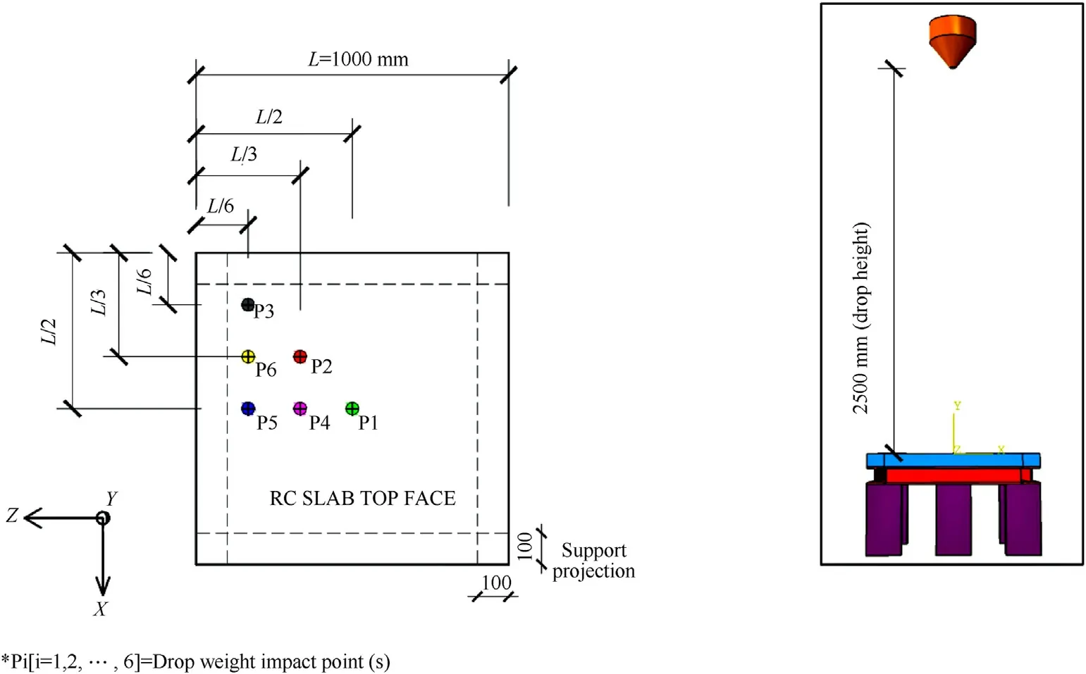
Fig.2.Considered eccentric locations of the drop weight impact (*Note: “L” is the span of the slab).
The numerical simulation of the slab under concentric impact P1 of the drop weight replicates the experiments by Sadraie et al.[1] conducted to investigate the performance of normal strength and high strength singly/doubly reinforced concrete slabs under concentric impact loading.The authors of the present study are sceptical about the dropping arrangement of the impactor made by Ref.[1] with regards to its concentric and flat impact onto the RC slab.
Non-linear dynamic analyses are performed only for the first free drop of the weight (steel impactor).Hence,the accumulated damage due to repeated impact loading is not simulated in this study.Mass and drop height of the impactor and support conditions of the RC slabs are taken in the same way as reported in Ref.[1].The explicit module of the employed software is utilized to perform non-linear incremental dynamic analysis.As the analysis requires a long period of time,a high-performance computer surface machine is used for solutions.In this way,numerical results have been obtained in a faster way.
ABAQUS/Explicit element library offers a variety of element formulations based on different integration approaches.To prevent negative volume effect and error termination [50,51,59,66,7,67],continuum 3-D stress 8-node solid element (C3D8R in [65]) with reduced integration and hourglass control is used to discretize concrete part,cylindroconical impactor,and steel beam/column supports,Fig.3(b).This element is widely used in the impact simulationsofthestructuralmembers[1,2,10,11,13,14,23,33,34,41,67].A 20 mm long 2-node beam element with 2 × 2 Gauss quadrature integration is selected to discretize the reinforcing steel bars.EMBEDDED_REGION (ER)constraint keycard in ABAQUS[65]is used to embed the reinforcing bars into the concrete part and to model the interface between the concrete part and embedded re-bars.The concrete part is chosen as the host region while the steel reinforcing bars are chosen as the embedded region [65].This constraint provides coupling and a perfect bond mechanism (i.e.,no sliding) for re-bar elements with elements of the concrete part.
Referring to Fig.3,the bottom end of the column supports is assumed fixed (i.e.,fully constrained to the ground) while all the bolt nodes on the bottom surface of the slab are made in contact with the supporting beams through hinged boundary conditions.The default “TIE CONSTRAINT” feature in ABAQUS is considered to provide interaction between the bolt nodes and flange top surface of the supporting I-beams.The contact interaction CONTACT SURFACE TO SURFACE is used to define the interaction between the steel beam and column supports.The default feature“AUTOMATIC GENERAL CONTACT”with friction and hard models is used to avoid the penetration between the slab surface and impactor (drop weight),and between the concrete and support meshes.While the surface of the impactor which applies impact loading is defined as master,the surface of the specimen (i.e.,RC slab) is defined as a slave in the software.Since friction losses occur during the experimental program,the coefficient of friction is taken as 0.02 for the contact surfaces.The interaction between the impactor and the steel re-bars is defined using the default feature “CONTACT AUTOMATIC NODES TO SURFACE” available in the ABAQUS code[65].In the numerical model,the slab has been restrained to satisfy the experimental boundary conditions of Sadraie et al.[1]providing an 800 mm clear span in each direction with 100 mm support width all-round.Material properties of solid-steel impactor have been taken from Ref.[1].
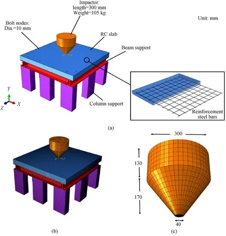
Fig.3.Schematic view of the developed 3-D numerical model: (a) 3D numerical model;(b) FE model;(c) Details of the impactor.
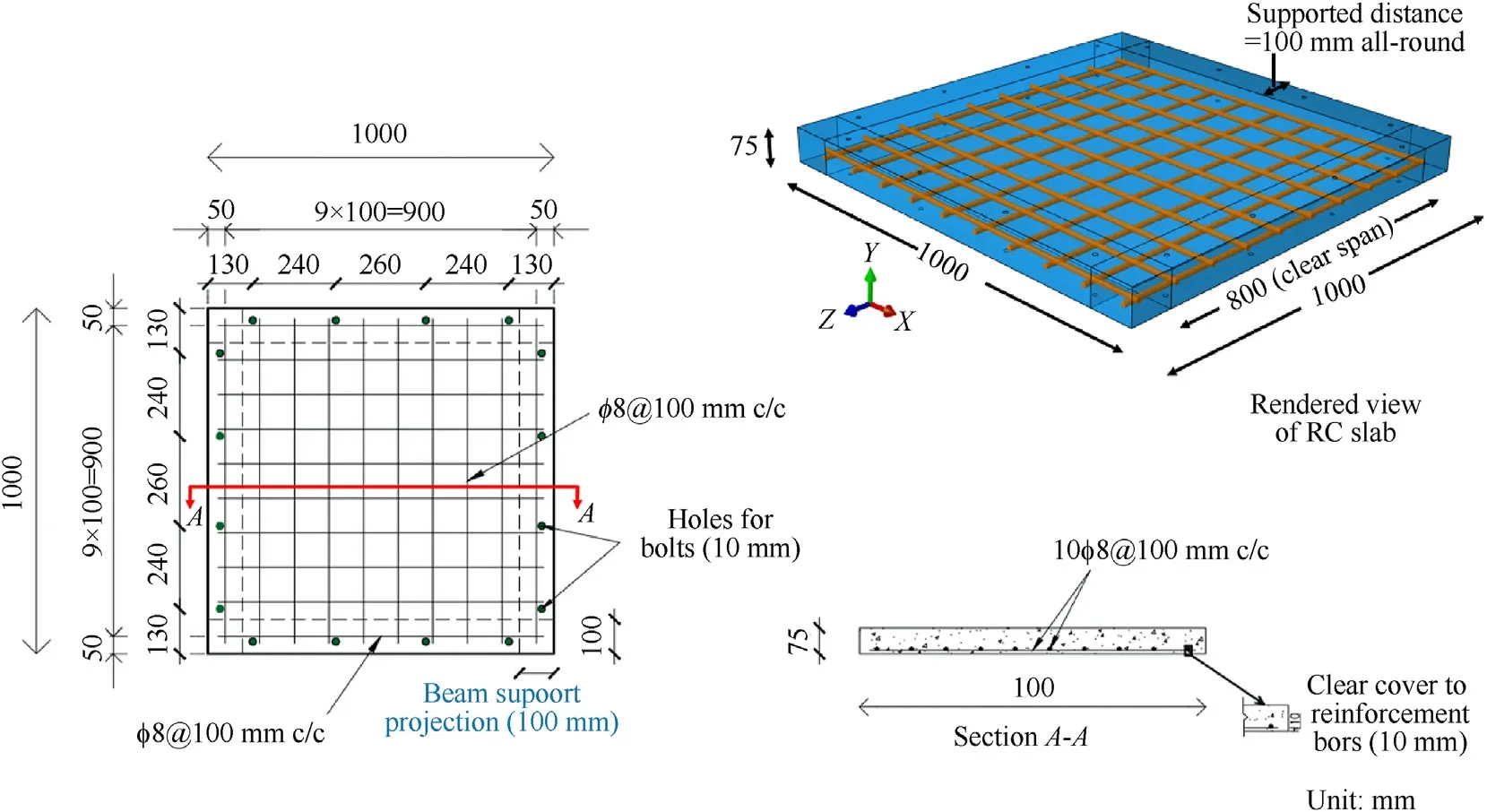
Fig.4.Reinforcement details of two-way conventional RC slab with tension reinforcement (0.88%) only.
The velocity at the impact of drop weight(free-fall)is calculated by Eq.(1):
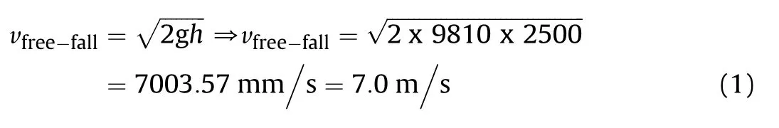
where vfree-fallis the velocity at the impact of drop weight,g is the acceleration due to gravity and its value is~9810 mm/s2(9.81 m/s2),and h is the height of the free fall or drop height(=2500 mm in this study).Following the law of conservation of energy,the drop weight has an impact energy of 2.57 kJ,calculated as EI=EPE(before the impact)=m*g*h=105*9.81*2.50=2575.12 J=2.57 kJ.From Newton’s second law of motion,the impact force is given as F=m*a=m*[(v-u)/t]=105*[(0-7.0)/0.71]=-1035.21 N=-1.03 kN(-ve sign indicates that the impact force opposes the original direction of motion).v=velocity after impact,u=velocity before impact,m=mass of the impactor,h=drop height,EPE=potential energy,t=time of impact,and a=acceleration (but in this case it is deceleration).The velocity calculated from Eq.(1)is applied to the impactor(drop weight)using the INITIAL_VELOCITY_GENERATION keycard in ABAQUS/Explicit [65].In addition to the initial velocity assignment,a constant mass acceleration of 9810 mm/s2is applied(or specified)to all nodes of the impactor using the LOAD_BODY_Y keycard [65] to simulate the gravitational effects.The steel impactor applies impact loading to the slab in a vertical direction.In other words,the impactor is allowed to translate vertically in the global Y-direction and restrained against the remaining degrees of freedom,same as considered by Ref.[1].A time period(step time)of 1.0 s (>tfree-fall) is assumed for the dynamic explicit analysis in this study to take into account the self-weight of the impactor.Also,it is assumed that this time duration is sufficient to evaluate the post-impact response of the slab (i.e.,peak displacement,acceleration,stresses,and damage).The time duration of a free-fall (tfree-fall) of the drop weight can be calculated by Eq.(2)

6.2.Constitutive material models used in modeling RC slab
The structural mechanics of concrete structures is paramount important,and concrete identification parameters including the non-linear stress-strain relation under imposing stress conditions and strain hardening/softening make the concrete response more complicated [55,68,7,69,70].The simulation of the concrete response using elastic damage models or elastic-plastic laws is insufficient for the purpose.Irreversible or plastic strain cannot be realized using the elastic damage model [7].
With often occurring blast explosions that have increased the demand of ensuring the safety of civilian and military structures,understanding the response of concrete under fast loadings like impact or blast holds great importance [68].The dependence of strain rate of the material behavior in dynamic loading conditions gives rise to material behavior that substantially varies from the response encountered under quasi-static conditions [71].This variation increases with the rise in the strain rate[68].Additionally,as compared to the reinforcing steel,larger deformation is developed by the concrete due to the wide distribution of micro-cracks prior to cracking and crushing in the instances of tensile and compressive failure [68,71].This puts forward the extra sensitive material response to the strain rate-dependent deformation.Therefore,the nonlinearity of concrete concerning the outcome of high strain rate deformation that takes place in a short duration should be taken into consideration for precisely outlining the response of concrete structures exposed to impact or blast loading[68,71].Impact loading generates high strain rates,often in the range of 102- 104s-1.RC structures,for example,are greatly influenced by this phenomenon.Its resistance can rise dramatically,with dynamic increase factors of up to 4 in compression and 6 in tension[25,68,7,72].
The response of concrete in short duration and high amplitude impulse loading and the behavior under static loading varies from each other[68,72].The concrete becomes a discontinuous structure when it is moderately loaded to failure and experiences extreme internal cracking,which results in dilation[68].Although,a swiftly loaded concrete specimen is not able to develop sufficient internal cracking in the lateral direction,which results in the formation of productive confining stress on its central core[68].This makes the concrete to be initially in a state of uniaxial strain with correlated lateral stresses that function as confinement.The lateral inertia confinement thus formed can end up causing not just a consequential rise in the dynamic strength but also an escalation in the critical strain [68].The entire episode/process is known as the inertia resistance effect.
6.2.1.Concrete damage plasticity(CDP) used for modeling concrete behavior to impact load
The Concrete Damage Plasticity (CDP) model in ABAQUS is a modification of the Drucker-Prager model proposed by Refs.[72,73].In this model,the shape of the failure surface in the deviatoric plane should not be particularly a circular figure,and it is controlled by the Kcparameter[58,7,67].This parameter is derived from the ratio of the gap between the hydrostatic axis,the compression meridian,and the tension meridian,respectively,in the deviatoric plane[58,67].This ratio is more than 0.50 invariably,and when the value becomes equal to 1.0,the deviatoric shape of the failure surface becomes a circle [58,67].In general,three key assumptions underpin the formulation of constitutive relationships in the plastic strain hardening-based material models: (1) the shape of the failure surface i.e.,initial yield surface behavior;(2)the development of the loading surface (hardening rule);and (3) the flow rule formulation [68].In addition to parameter Kc,the CDP model is elucidated by four additional parameters: a) the angle of dilation;(b) the flow potential eccentricity: (c) the ratio of initial equibiaxial compressive yield stress to initial uniaxial compressive yield stress;and(d)the viscosity coefficient.The default values for these five parameters are given in Table 1.Additional information concerning the model can be found in Refs.[58,65,7,67].
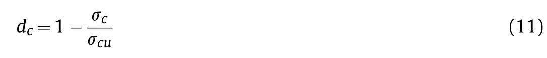
Cracking under tension and crushing under compression of the concrete are considered the two common failure mechanisms of the CDP model [58,7,65].The model works on the theory of isotropic damage evolution in integration with isotropic tensile and compressive plasticity to reflect the inelastic and fracture response of the material [65].The model also recognizes the visibility/preciseness of strain hardening in compression and strain softening in tension.The stress-strain curves endorsed for the model have exponential softening in tension and parabolic hardening followed by exponential softening in compression [7,65].Generally,the model uses the yield function,which shows the yield surface related to the effective stress to obtain the position of damage[7,65].The yield surface is connected to equivalent plastic strains in tension and compression [65].As shown in Fig.5,the behavior of concrete while unloading is enervated by the degradation of the elastic stiffness of the concrete [65].This degradation is represented by two scalar damage variables: tension damage (dt) and compression damage(dc)falling in the range of 0(undamaged)and 1 (totally damaged) [65].
The total strain(ε)has its elastic and plastic components,εeland εpl.

The stress tensor (σ) is defined as
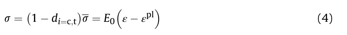
Here,d=scalar degradation variable,=effective stress,E0=initial concrete elastic modulus.The elastic stiffness of the concrete is progressively degraded using a single scalar degradation variable,d,calculated based upon a relationship between the damage dissipation energy(DDE)and the total absorbed energy(Q)imparted[49,7,65],given as
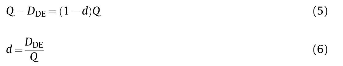
DDEis a mechanical strain-based dissipated energy by the damage[65].During an analysis,once the new strain increment is estimated from the current strain state,and the resultant damage factor,d,found.If DDEis zero,then d will be zero and the material will remain undamaged [58,65].Once the DDEincreases,the new stress state is calculated for the degraded concrete stiffness and passed back to ABAQUS/Explicit along with the internal energy for the next increment [58,65].In general,the calculation of DDEis dependent upon the strain field,characterization constants,and material volume [65].
(1) Concrete compressive behavior
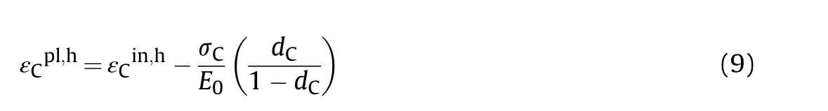
In CDP model,the equivalent compressive plastic strain εpl,hcplayed a paramount role in describing the relation between the concrete compressive strength and damage parameters (Fig.5(a))as follows:
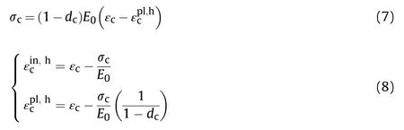
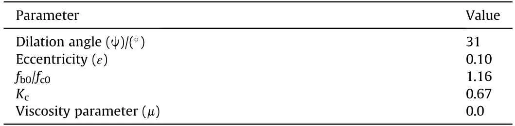
Table 1 Default parameters for the CDP concrete model,taken from Refs.[58,65].
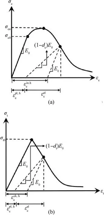
Fig.5.Concrete response in CDP model to uniaxial loading conditions [58,65]: (a)Compression,and (b) tension.
In ABAQUS,the user provide the (dc-εpl,hc) data.In return,ABAQUS will internally compute the plastic strain as follows:
Ideally,the damage parameter is deduced from a material test with ramped loading/unloading cycles as follows:
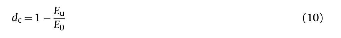
In the absence of such data,the damage parameter can be approximated as
(2) Concrete tensile behavior
In CDP model,the equivalent tensile plastic hardening strainis derived (Fig.5(b)) as follows:
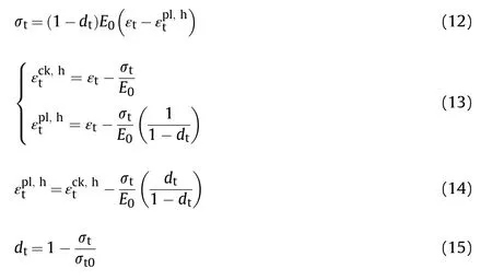
where,(1-di=c,t)E0=Euis the reduced elastic modulus of the concrete (or unloading stiffness).Experimental data of the study conducted by Hafezolghorani et al.[58]are used to incorporate the concrete plasticity for the CDP model.Normal strength concrete has 28-day average static compressive strength 29.70 MPa,mass density 2340 kg/m3,elastic modulus 30.91 GPa,and Poisson's ratio 0.20,reported in Ref.[1].The static tensile strength (f't) of the concrete is calculated by Eq.(16),given by the CEB-FIB Model Code[1,73,70].
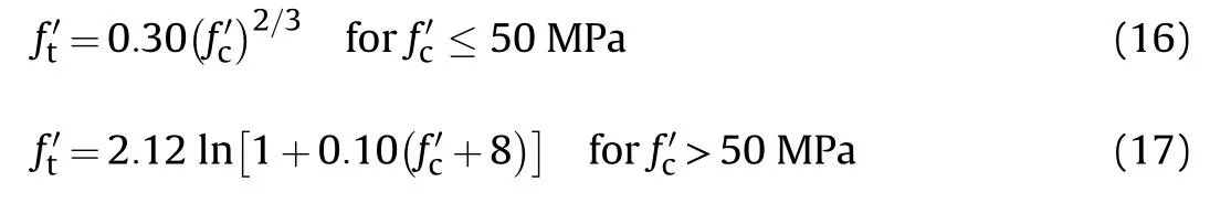
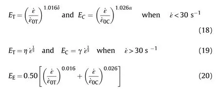
where f'cis the cylinder compressive strength of the concrete(MPa).The tensile strength calculated using Eq.(16) is 2.88 MPa [1].The strain rate effect on the concrete is incorporated in the study using the CEB Code[74]formulation.DIF for young's modulus(EE),tensile modulus (ET),and compressive modulus (EC) are calculated using the following equations:
6.2.2.Holmquist-Johnson-Cook (HJC) used for modeling concrete behavior to impact load
In the HJC model,before reaching a stipulated failure criterion,the material is considered linear elastic[66,68,75].The damage will cumulate when further loading is applied until complete failure takes place,surpassing which the material continues to stay at a residual state [68,71,75].The strength surface after it has experienced failure is computed by decreasing the cohesion strength value of the initial failure surface [68].In the finite element software-ABAQUS-the accumulation of damage is identified using the scalar damage factor -d (level of damage) or plastic strain[66,68,75].This value ranges between 0 and 1,for no damage and complete damage respectively,as per each model failure surface[75].
For tracking the nonlinear response of RC structures during dynamic loading,stress-strain relation has to be described [68].Many mathematical models are presently being exerted in the numerical investigations of RC structures,out of which,this study endorses the monotonic uniaxial stress-strain relation prior to the peak stress suggested by Scott et al.[76] owing to its simple and computationally efficient behavior.As presented in Fig.6(a),in this model the stress-strain relation of concrete in compression is devised of a parabola until it reaches the compressive strength fc.Beyond this compressive strength,the compressive stress falls in line with the rise in the compressive strain until it becomes compressive ultimate strain ∊cu[68,75].At a point where the strain reaches a value higher than the ultimate strain value of ∊cu,the concrete in compression has no more resistance capacity due to crushing [68].Looking at the other way,the concrete in tension is presumed to be linearly elastic until it reaches a point of tensile strength ft,and afterward portrays linear strain-softening behavior,as shown in Fig.6(b).The ultimate strain for the cracking corresponding to the case is taken as ∊tu=0:1∊cu.When a structure is exposed to impact loading,the unloading and reloading of stresses will occur in a relatively small local region that does not affect the overall structural response [68].However,a linear unloadingreloading stress-strain relation (Fig.6) parallel to the secant modulus in both compression and tension is assumed in the present study for computational convenience [68].
In this study,the Johnson Holmquist Cook approach is used to model concrete constitutive relationships,which is developed for defining the concrete behavior under extreme loading conditions involving high strain rates such as impact and blast [59,68,7,75].The concrete strength is affected by pressure,strain rate,and accumulated damage,where the damage is an outcome of pressure and plastic strains that are encountered over time.The equation given below represents the relation between applied pressure and effective material stress

where σ*is the equivalent stress normalized to compressive strength of concrete,given as σ*=where fcdynand fcare dynamic and static compressive strength of the concrete(MPa);˙εdyncis the corresponding compressive strain rate;A,B,C,and N are the material constants and their values can be obtained through the Splits-Hopkin-Pressure-Bar (SHPB) test;P*is the applied pressure(MPa),given as P*=and D represents the damage coefficient.The uniaxial tensile strength of the concrete is given as
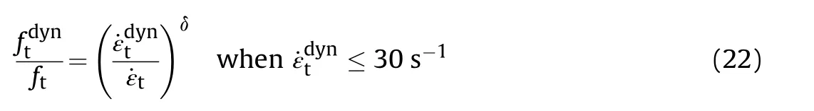
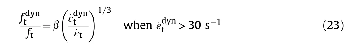
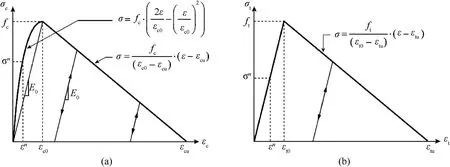
Fig.6.Concrete response in HJC model to uniaxial loading conditions [68]: (a) Compression region and (b) tensile region.

Here,Pcrush=pressure corresponding to initial crushing of the concrete;Plock=the pressure at which all voids are collapsed;K1,K2,and K3=material constants;and=a measure of volumetric strain,reported in Ref.[68].The material parameters used for the HJC model taken from Holmquist et al.[75] and Williamson et al.[77,78] are given in Table 2,also reported in Ref.[79].Additional information regarding the HJC model can be found in the CEB-FIB model code [74].
6.2.3.Malvar and Crawford model used for modeling steel bars
Although reinforcement steel,unlike concrete,typically exhibits a similar response under compression and tension loadings,even though,the stress-strain relationship of steel displays the same stress-strain curve in compression and tension [66,68].However,its dynamic properties are comparable to those of concrete [68].The yield strength and ultimate tensile strength both rise as the strain rate increases [74].Fig.7 shows the strain rate associated with different structural loads and various mechanical methods to characterize these loadings under such rates [49].Although steel bars are more susceptible to temperature effects,the changes in mechanical properties with temperature are neglected in this study on account of the use of the reinforcing steel as steel wire mesh typically surrounded by the concrete matrix having very low thermal conductivity,and the concrete crushing/perforation due to impact load occurs in a very short duration of time [66,68].This makes it difficult to transfer the generated temperature effects to the reinforcing steel [68].The stress-strain relationship can be simplified when the reinforcing steel is used as supplemental material in the construction (or modeling) of the RC slab [68].
In this study,the reinforcing steel has quasi-static yield strength 2131με,average static yield strength 422 MPa,ultimate tensile strength 651 MPa,ultimate elongation 21.30%,mass density 7800 kg/m3,elastic modulus 198 GPa,and Poisson's ratio 0.30,reported in Ref.[1].The strain rate effect is incorporated using the Malvar and Crawford [80] material model,same as was used by Ref.[1].A dynamic increase factor(DIF)of 1.24 is considered in the numerical analysis,calculated using the following equation:
Table 2 Concrete parameters for the HJC model,adapted from Refs.[68,70,77-79].
Fig.7.Methods of mechanical characterization and corresponding strain,adapted from Ref.[59].
Here,fy=yield strength(MPa);and ˙ε=reference strain rate(s-1).This formulation is valid for steel yield strength ranging from 290 to 710 MPa [80].The calculated dynamic yield strain and yield strength of the steel bars are 2642με and 524 MPa,respectively[1].It is noted that the reinforcement is taken as completely bonded to the concrete until the surrounding concrete elements are disintegrated [65].
A kinematic,elastic-plastic idealization [65,7,67] is considered for modeling the impactor and the supporting steel beams/columns,same as was used by Sadraie et al.[1].This idealization consists of the elastic section,a yield plateau,and a work hardening region.The mass density,elastic modulus,yield strength,and Poisson's ratio of the supporting steel beams/columns taken from Ref.[1] are 7850 kg/m3,198 GPa,400 MPa,and 0.30,respectively.The solid-steel impactor has yield strength 550 MPa,Young's modulus 198 GPa,mass density 7850 kg/m3,and Poisson's ratio 0.30,also reported in Ref.[1].
6.3.Validation of the numerical model
Even though the computer code ABAQUS/Explicit has been extensively used by the researchers to validate their numerical models against the experimental data on reinforced concrete structural components under quasi-static and impact loading conditions [2,24,25,59],validation of the results with the experimental observations seems necessary for the authenticity of extended analyses.In this paper,the key studied parameter is the impact location of the drop weight on the dynamic behavior of the conventional RC slab subjected to impact load.
The developed FE numerical model is validated with the results from an experimental study conducted by Sadraie et al.[1].Impact load of 105 kg from a height of 2500 mm is delivered to the slab center using the ABAQUS/Explicit-solver.
6.3.1.Peak vertical displacement
The mesh convergence test is conducted with RC slab under concentric (P1) impact loading,as per Fig.2,and seed sizes range from 10 to 25 mm.Table 3 shows the results from the convergence tests and lists the peak displacement of the slab,peak vertical acceleration,damaged area,computational time,the total number of elements generated,and computer disk space used for the different seeds.It is worth mentioning here that the Microsoft computer surface machine having 11th Generation intel core i5 processor mated with 16 GB of RAM has been used for the present numerical study.The time history of the slab displacement computed using the CDP model for different seed sizes is given in Fig.8.The peak vertical displacement increases with an increase in the element mesh size.The slab with 10 mm seed has a peak displacement of 32.82 mm (17% higher than experimental) while the 25 mm seed shows a much higher peak displacement of 43.28 mm(54%higher than experimental).The 15 mm and 20 mm seeds result in peak displacement of 35.13 mm (25% higher than experimental) and 38.65 mm (37% higher than experimental),respectively.Using the HJC model,the slab with a 10 mm mesh size results in a peak vertical displacement of 35.34 mm which is 26% higher than the measured one and 8% higher than that obtained through the CDP model with the same size of the element,Table 3 and Fig.9.Therefore,with the CDP model,the 10 mm element size,with a difference of 16% in peak displacement,is deemed reasonable to predict the response of the slab in terms of peak displacement under the considered impact load.Further decrease in element size increases the running time without making a significant influence on the computational results.It is noted that the variation in the results of computational analyses and experimental work is on account of the (1) idealization considered in the modeling of supports and materials,(2) use of default interactions between bolt nodes and flange surfaces,and (3) finite element size.
6.3.2.Peak vertical acceleration
Acceleration-time plots of the slab modelled with different element sizes are shown in Fig.10.These plots are obtained by taking the average of the vertical acceleration at four considered adjacent nodes of the concentric impact P1.The peak maximum acceleration of the slab increases with an increase in the size of the element.From the comparison of values in Table 3,it is observed that the slab modelled with CDP with 10 mm mesh size exhibits a peak maximum acceleration of 294.73 g which is quite close to the measured one(288.95 g)as compared to other sizes of the element.Also,the increase in the element size of the slab 10-25 mm increases the peak acceleration by 32% from 294.73 to 390.14 g.Comparing the peak acceleration of the slab modelled with CDP and with the HJC model,the HJC model predicts maximum acceleration much greater than the measured one under the similar impact load and mesh size (10 mm),Table 3.
Referring to Fig.8,the slab starts deflecting the moment the impactor comes in contact with the top face of the slab i.e.,after 0.71 s which is the time of free fall.It attains a peak vertical displacement at t=0.735 s i.e.,0.025 s after the contact followed by a decrease in the displacement of the slab on account of the elastic response of the slab and restitution characteristics of the slab and the impactor to a value of 2.40 mm at almost t=0.79 s.From 0.79 to 0.798 s i.e.,for a small duration of 0.008 s,the slab momentarily remains at rest i.e.,under gravity (1 g ≪100 g ≈0.0),and subsequently undergoes a random variation of the acceleration fluctuating with as high as+300 g and as low as -100 g,Fig.10.
Table 3 Mesh sensitivity analysis of RC slab under concentric impact P1.
Fig.8.Comparison of displacement-time history plots for various seed sizes of RC slab subjected to concentric impact P1.
6.3.3.Damage profile
Fig.11 shows the observed damage pattern on the bottom surface of the RC slab from the drop weight test and finite element simulation under impact loading.The impactor perforates the concrete slab through punching and concrete scabbing occurs along with a few flexural and predominating diagonal cracks.The fringe levels shown in Fig.11 are associated with the extent of damage to the slab: fringe level of 0.00 indicates no damage;0.49 represents the initiation of softening process in the concrete,and 0.99 shows severe damage i.e.,total loss of stiffness and strength of concrete.In addition to the concrete CDP model that incorporates both strength and stiffness softening,once an element achieves a failure (principal) strain of 0.003729,it is assumed to be so extensively damaged that it is eliminated from the model in order to avoid extremely distorted elements and to mimic fracture debris.Exposed surfaces of the elements as a result of deletion are bound by new contact surfaces,which prevent them from undergoing substantial plastic deformation from entering others and allow shattered fragments to clash.Here,the steel reinforcement is considered to be entirely bound to the concrete part until the surrounding concrete elements crumble.Referring to Table 3,the concrete perforation area increases with an increase in the size of the element mesh.It can be noticed from Fig.12,the pattern of damage on the bottom surface of the slab in the case of the HJC model results in a very conservative prediction with regards to greater surface damage and concrete scabbing zone than the values reported in the experimental impact tests by Ref.[1].However,the CDP model with strain rate effect reproduces well the overall damage pattern on the bottom surface of the slab under a similar impact load and mesh size (10 mm).It is noted that the overestimation of the results or slab response with the HJC model is linked to the rapid descending of the material model behavior towards an effectively zero stress state following a tension/shear controlled damage process,and the consequent diminish of the interaction capacity between the steel re-bar and the surrounding concrete.Thus,taking into account the field conditions of the experiments by Sadraie et al.[1],the agreement of the numerical(with CDP) and experimental values with 10 mm element size is quite reasonable.Although the compatibility is strong between computed numerical (with CDP) and available experimental results,there are still some error rates.It is thought that friction effects,inner cracks in concrete,difficulties in providing perfect support conditions during the numerical study,and dynamic characteristics of the materials used in the numerical analysis are the main reasons for the differences between results.

Fig.9.Comparison of displacement-time history plots for two considered concrete models of RC slab with 10 mm element size under concentric impact P1.
6.4.Results and discussion
Table 4 lists the computed values of peak displacement,maximum acceleration,maximum damage dissipation energy,and damage mode of the slab corresponding to the concentric and eccentric impacts at step time t=1.0 s.Displacement profiles of the slab for the six considered locations are presented in Fig.13 while the displacement distributions of the slab and the reinforcement are shown in Fig.14 and Fig.15,respectively.The maximum principal stress distribution of the tension steel is presented in Fig.16.The positive value of the principal stress indicates tension.Fig.17 shows the time history of the principal tensile stress of the reinforcing steel bars obtained by taking the average of 4-5 adjacent considered beam elements at the considered locations of the impact.The variation of damage dissipation energy (DDE) with time is shown in Fig.18.The computed damage patterns on the top and bottom surfaces of the slab are shown in Fig.19 and Fig.20,respectively,where a fringe level of 0.99 indicates that the concrete is severely damaged.The initiation of softening behaviour in the concrete corresponds to a fringe level value of approximately 0.50.Erosion can be described as the deletion of an element from the numerical calculation when a predefined limit is reached.When the element undergoes extreme deformations in the case of erosion algorithm’s absence,this may cause “lock-up” which leads to numerical instabilities.To avoid highly distorted elements and to simulate fracture debris,in addition to the concrete CDP that includes both strength and stiffness softening,once an element reaches a principal strain of 0.003573,the element is taken to be so badly damaged that it is deleted from the model.Exposed element surfaces caused by deletion are bound by new contact surfaces,which prevent elements undergoing large plastic displacements from penetrating others and allow fragmented pieces to collide.
6.4.1.General observations
From the finite element analyses conducted,the following observations are worth mentioning:
• The slab under the considered locations of the impact exhibits local response including concrete spalling on the impacting face of the slab,scabbing on the rear face,perforation,and yielding of the tension reinforcement,Fig.19 and Fig.20.
• The impacted portion and its surrounded concrete of the slab get pushed by the impactor through punching and the slab undergoes a combination of different modes of failure having a predominance of modes with the different eccentricity of the impact load,Table 4.
• In general,the concrete of the slab experiences greater deformation than the reinforcing steel because of punching and extreme localized bending/shearing in the concrete,Fig.14 and Fig.15.
• Change in the location of the drop weight significantly influences the damage dissipation energy,peak acceleration,maximum displacement,and damage pattern,Table 4.
• The crack density on the bottom tension surface is much greater than on the impact face of the slab for the considered impact loadings.This increase in crack density and crack depth on the tension face is because of the poor tensile strength of the concrete.
• Location of the drop weight and boundary conditions of the slab significantly influence not only the crack pattern but also the concrete scabbing/spalling area and size of the perforation.
• Referring to Table 4,the location of the impactor also influences the peak vertical acceleration of the slab showing the variation of its stiffness and rigidity.
• Localized two-way shear under the impactor colludes with beam shear for eccentric impacts P3,P5,and P6 (Fig.20).
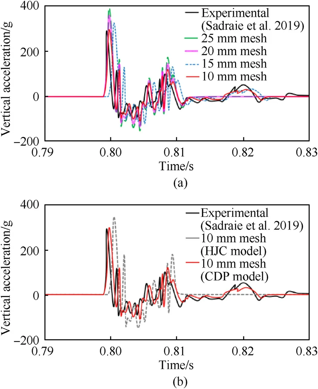
Fig.10.Comparison of acceleration-time history plots of RC slab under concentric impact P1: (a) Comparison of spatial acceleration time-history plots for various mesh sizes of RC slab modelled with CDP under concentric (P1) impact loading;(b) Comparison of acceleration time-history plots for two considered constitute models of RC slab CDP under concentric (P1) impact loading.
6.4.2.Slab response to impact loading
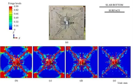
Fig.11.Comparison of damage profiles of experimental and numerical RC slabs for various seeds under concentric impact loading:(a)Experimental slab(Sadraie et al.,2019[1]);(b)25-mm mesh;(c) 20-mm mesh;(d) 15-mm mesh;(e) 10-mm mesh.
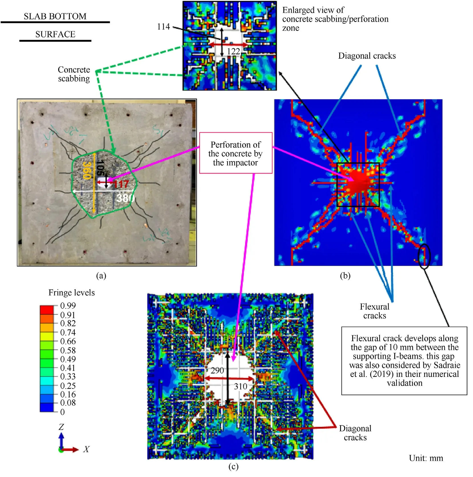
Fig.12.Comparison of damage profiles of experimental and numerical RC slabs for two concrete models under concentric impact P1:(a)Experimental slab(Sadraie et al.,2019[1]);(b) CDP model damage prediction with 10 mm mesh size;(c) HJC model damage prediction with 10 mm mesh size.
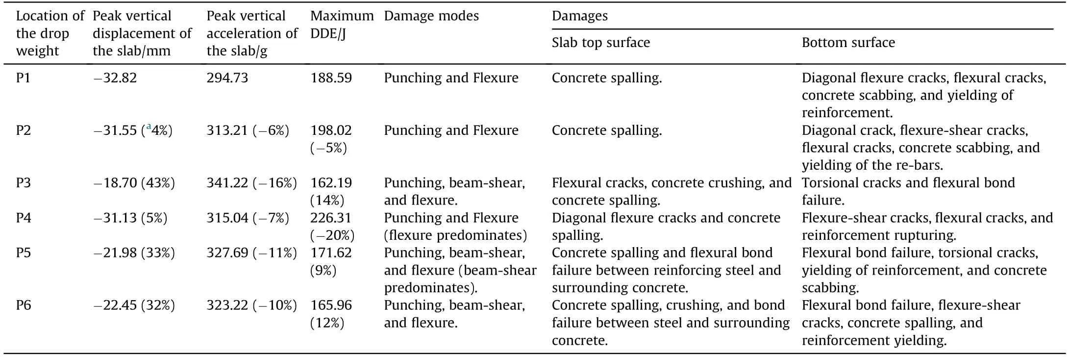
Table 4 Summary of the responses obtained from the numerical analyses.
Dynamic response of RC slab in the event of impact loading may be explained as follows: (a) Prior to the event,the slab has little displacement due to its own weight;(b) Duration of dynamic response during an impact is location-stiffness specific of the slab,and development of localized tension membrane takes place for concentric P1 and eccentric impacts P2 and P4 only,while for eccentric impacts P3,P5,and P6,the beam-shearing effect predominates,Fig.13;(c) Initiation of the damage,damage duration,and total damage (DDE) are impactor location-specific,Fig.18;(d)For the eccentric locations P3,P5,and P6-lower yield stresses are observed on account of predominating shearing of concrete at the support(s) than concentric (P1) as well as less eccentric locations(P2 &P4),Fig.17 and Fig.20;and (e) the slab behaves as a membrane in the outer region around the perforation area of the concrete developing radial cracks in tension zone accompanied with high shear stress make to cause spalling and scabbing of the concrete in the vicinity of impacting area of the slab,Fig.21 and Fig.22.
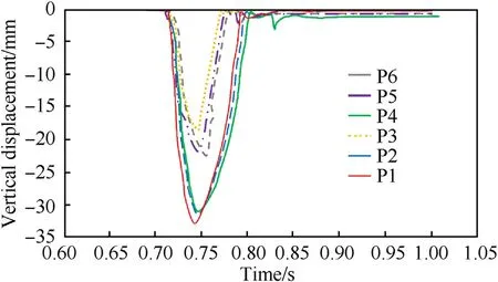
Fig.13.Y-displacement-time history plots for the considered locations of the impact.
6.4.3.Diagonally eccentric impacts,P2 and P3
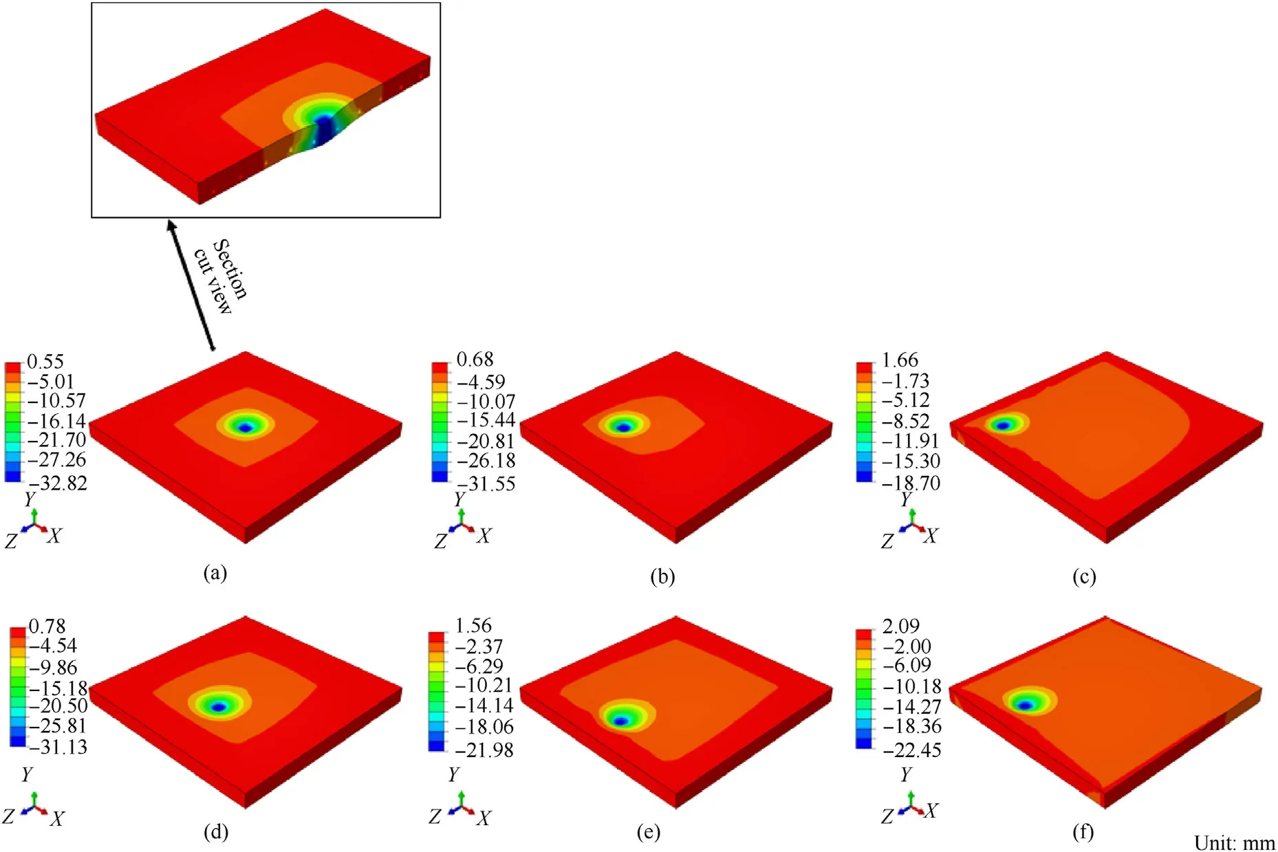
Fig.14.Y-displacement (mm) distribution of the slab under the concentric (P1) and eccentric impact loadings: (a) P1;(b) P2;(c) P3;(d) P4;(e) P5;(f) P6.
The diagonally eccentric impact(P2)causes more localized and severe damage in the form of flexural bond failure between the reinforcing steel bars and the surrounding concrete as compared to concentric impact(P1),Fig.20.Long flexure cracks develop on the bottom surface of the slab.The damaged area is more than that of the concentric impact P1.Diagonally impact P2 increases the DDE(damage) by 5% from 188.59 (P1) to 198.02 J which is because of higher stresses in concrete.However,the maximum vertical displacement decreases by 4%from 32.82 to 31.55 mm,Table 4.For eccentric impact P3 i.e.,near the corner of the slab,the slab experiences much less peak vertical displacement (18.70 mm) as compared to eccentric impact P2 or concentric impact P1 on account of the restraint provided by the supporting beams,and therefore the damage of the slab reduces by 14%from 188.59(P1)to 162.19 J.From Fig.20,the observed failure modes for eccentric impact P2 are punching and flexure while the slab under eccentric impact P3 has a combination of punching,shear,and flexure modes.The reinforcing steel bars experience peak vertical displacements of 27.92 mm and 13.42 mm,respectively,under eccentric impacts P2 and P3.The maximum tensile stress in the re-bars exceeds the yield strength of the steel (422 MPa) under eccentric impact P2;however,the stress in case of impact P3 is within the yield stress level,Fig.16.
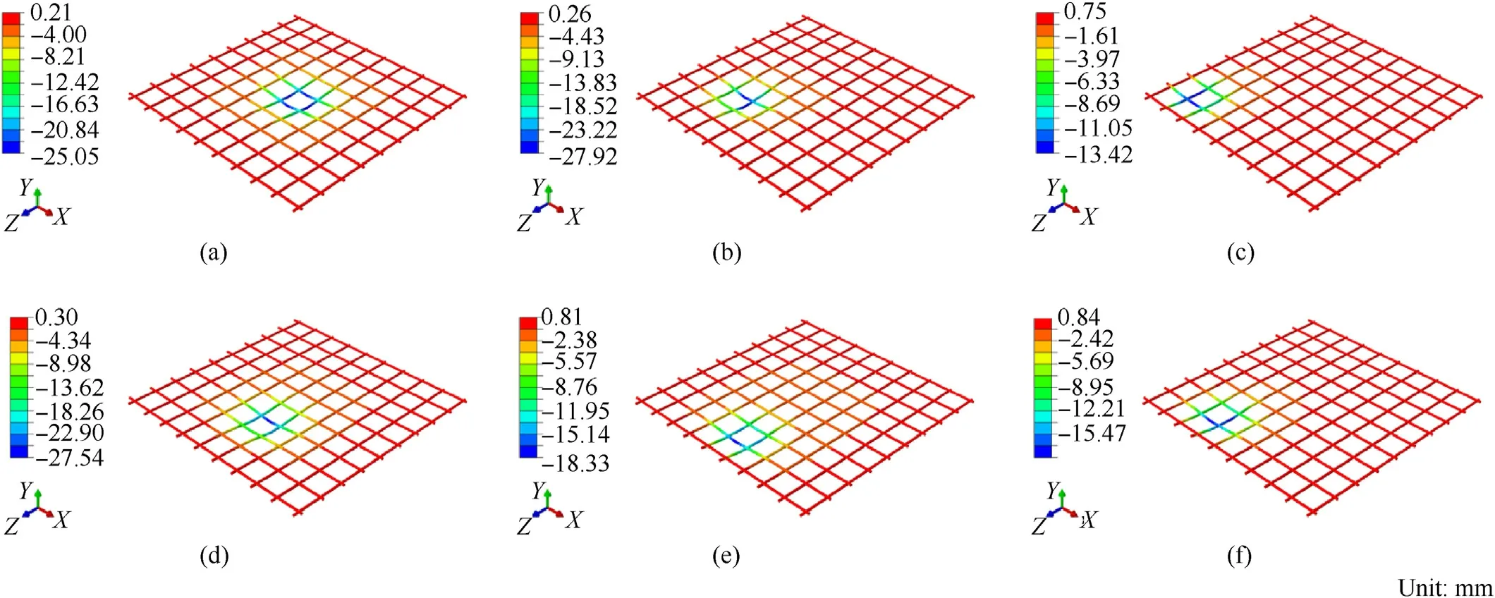
Fig.15.Y-displacement (mm) distribution of the reinforcing steel bars of the slab under the concentric and eccentric impact loadings: (a) P1;(b) P2;(c) P3;(d) P4;(e) P5;(f) P6.
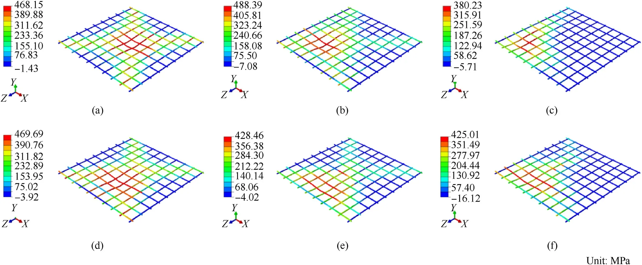
Fig.16.Principal stress (MPa) distribution of the reinforcing bars under the considered impact loadings: (a) P1;(b) P2;(c) P3;(d) P4;(e) P5;(f) P6.
Fig.17.Tensile stress-time history of the steel bars under concentric and eccentric impacts.
Fig.18.Damage dissipation energy (DDE) plots for concentric and eccentric impacts.
Fig.19.Damage profiles on the top face (impact face) of RC slab under the considered locations of the drop weight (t=1.0 s): (a) P1;(b) P2;(c) P3;(d) P4;(e) P5;(f) P6.
It is worth mentioning that the tensile stress in the tension reinforcement steel of the slab under diagonally eccentric impact P2 is larger than under concentric impact P1 as well as other eccentric impacts(P3-P6).This is on account of the combination of bending and torsional moment due to warping developed for this eccentricity of the drop-weight,Fig.16.
6.4.4.Eccentric impacts along the mid-span,P4 and P5
Total damage for the eccentric impact of the drop weight along the mid-span i.e.,P4,is predicted to be 226.31 J (20% greater than concentric impact P1)but the peak vertical displacement of the slab is 31.13 mm which is less than that for the concentric impact P1,Table 4.The damage of the slab by impact P4 is maximum owing to higher stresses develop in the materials of the slab.For eccentric impact P5,the DDE (damage) reduces by 9% from 188.59 (P1) to 171.62 J,and the peak vertical displacement of the slab significantly decreases to 21.98 mm,Table 4.This decrease in the displacement and damage is because of the shear-span effect of the eccentric loading.
6.4.5.Eccentric impact,P6
Fig.20.Damage profiles on the bottom tension face of RC slab under the considered locations of the drop weight (t=1.0 s): (a) P1;(b) P2;(c) P3;(d) P4;(e) P5;(f) P6.
For impact P6,the total DDE(damage)and peak displacement of the slab are computed to be 165.96 J (12% lesser than that of concentric impact P1) and 22.45 mm (32% lesser than impact P1),respectively,Table 4.Observed damage modes for this location are punching,flexure,and beam-shear,Fig.20.
From the above discussion of results,the following eccentric severity of the impact from the degree of damage has been arrived at in this study: P4 >P2 >P1 >P5 >P6 >P3 (see Fig.23).
7.Conclusions
In this research work,the damage response of eccentric impact from the rigid drop weight on a two-way 1000 × 1000 × 75 mm3conventionally reinforced concrete slab with tension reinforcement only (0.88%) has been investigated through FEM-based dynamic computer code,ABAQUS/Explicit.In addition to the concentric location of the impacting device (P1),a total of five eccentric locations(P2-P6)which represent the coverage of the entire slab are considered in the study.The slab is impacted by hard steel cylindroconical impactor(or striker)with a flat nose of diameter 40 mm,having a total mass of 105 kg released from a fixed height of 2500 mm with a velocity of 7.0 m/s.Two well-known mathematical concrete models namely;Concrete Damage Plasticity (CDP) and Holmquist-Johnson-Cook(HJC),are used for predicting the damage to the slab.Dynamic increase factors as per fib MODEL CODE 2010 are used to account for the strain rate effect of the materials.Response of the slab to impact loadings and its load-carrying mechanism are explained.Lastly,the severity order of the eccentricity of impact loading from damage point of view is ascertained.
From the numerical results,it is found that the predictions made by the HJC concrete model are very conservative with regards to excessive perforation and concrete scabbing on the bottom surface of the slab while the CDP model well reproduces the damage pattern as well as other responses such as peak displacement and acceleration under the concentric impact P1.Both experimental and numerical results (with 10mm mesh) are found to be compatible with each other and a good relationship is obtained between the results.Besides,the average value of the ratio of experimental values to numerical results is 0.98 for peak acceleration and 0.86 for peak vertical displacement,respectively.Concrete scabbing zone,perforation area,peak vertical displacement,maximum acceleration,crack pattern,damage/failure mode,and damage dissipation energy are the parameters greatly influenced by the impact drop weight loading with varying eccentricity.Punching failure mode predominates in each of the considered locations of the impact accompanied by bending and shear.The slab response is primarily governed by local failure modes.The damaged area under the eccentric impact P4 i.e.,at an eccentricity of 1/6th of the span along the mid-span from the centroid of the slab,is much greater than concentric impact P1 and each of the other considered eccentric impact loadings.Moreover,the total damage dissipation energy (DDE) of the slab with this eccentric impact is 1.20 times more than that for the concentric impact of the drop weight.Also,the DDE for the impact P4 is found much higher than each of the other considered eccentric impacts.The maximum damage under the impact P4 is on account of the development of additional torsional stresses in the slab associated with this eccentricity of the drop weight.The restraint boundary condition influences the damage response of the slab with the eccentricity of the impactor exceeding 1/6th of the span (shear-span effect) from its centroid and alters the mode of failure to beam-shear because of which the damage (DDE) and displacement decrease.
The present study clarifies the fallacy of maximum damage to the slab due to centroid drop weight impact on it.The most critical location of the impact is not the centroid of the slab but the eccentric one with the eccentricity of 1/6th of the span from the slab centroid along the mid-span.
Fig.21.Stress distribution (MPa) of the slab under eccentric impact P4.
Fig.22.Stress distribution (MPa) of the slab under concentric impact P1.
Fig.23.Severity order of the eccentricity of impact loading from damage point of view.
Credit author statement
S M Anas: Formal analysis,Investigation,Methodology,Resources,Validation,Writing - original draft,Software;Mehtab Alam: Conceptualization,Supervision,Visualization,Writing - review&editing.Mohd Shariq: Software,Writing -original draft.
Funding
The authors received no financial support for the research,authorship,and/or publication of this article.
Declaration of competing interest
The authors declare that they have no known competing financial interests or personal relationships that could have appeared to influence the work reported in this paper.
Acknowledgments
The authors express their sincere gratitude to the Civil Engineering Department of Jamia Millia Islamia (A Central University),New Delhi,India for providing the computational facilities for carrying out the present finite element analyses.Sincere appreciation is due to Emeritus Professor T K Datta from the Indian Institute of Technology Delhi(IIT-D),India for their assistance in this research work.Authors would also like to thank Emeritus Professor N K Gupta from IIT-D for providing guidance to understand impact loading.
杂志排行

Defence Technology的其它文章
- A review on the high energy oxidizer ammonium dinitramide:Its synthesis,thermal decomposition,hygroscopicity,and application in energetic materials
- Blast wave characteristics of multi-layer composite charge:Theoretical analysis,numerical simulation,and experimental validation
- Task assignment in ground-to-air confrontation based on multiagent deep reinforcement learning
- Deep learning-based LPI radar signals analysis and identification using a Nyquist Folding Receiver architecture
- A small-spot deformation camouflage design algorithm based on background texture matching
- Quasi-static and low-velocity impact mechanical behaviors of entangled porous metallic wire material under different temperatures