Analysis and design for the comprehensive ballistic and blast resistance of polyurea-coated steel plate
2023-01-18DongyangChuYigangWangShanglinYangZhijieLiZhuoZhuangZhanliLiu
Dongyang Chu,Yigang Wang,Shanglin Yang,Zhijie Li,Zhuo Zhuang,Zhanli Liu
Applied Mechanics Laboratory,Department of Engineering Mechanics,School of Aerospace Engineering,Tsinghua University,Beijing,100084,China
Keywords:Polyurea Ballistic and blast resistance Combined fragments and blast loading
ABSTRACT Fragments and blast waves generated by explosions pose a serious threat to protective structures.In this paper,the impact resistance of polyurea-coated steel plate under complex dynamic loading is analyzed and designed for improving comprehensive ballistic and blast resistance using the newly established computational evaluating model.Firstly,according to the thickness and placement effects of the coating on the impact resistance,the steel-core sandwich plates are designed,which are proved to own outstanding comprehensive ballistic and blast resistance.Besides,the distribution diagram of ballistic and blast resistance for different polyurea-coated steel plates is given to guide the design of protective structures applying in different explosion scenarios.Furthermore,the dynamic response of designed plates under two scenarios with combined fragments and blast loading is studied.The results show that the synergistic effect of the combined loading reduces both the ballistic and blast resistance of the polyurea-coated steel plate.Besides,the acting sequence of the fragments and blast affects the structural protective performance heavily.It is found that the first loading inducing structural large deformation or damage is dominant.When fragments impact first,the excellent unit-thickness ballistic performance of the structural front part is strongly needed for improving the comprehensive ballistic and blast resistance.
1.Introduction
Explosions are recognized as a significant threat to both civilian and military equipment.It can form both blast waves and fragments,causing serious damage to the protective structures,as shown in Fig.1.The complex combined loading brings lots of challenges for designing protective structures with excellent comprehensive ballistic and blast resistance since the ballistic and blast damage mechanisms are quite different [1].
Recently,developing the light protective structure through metal-elastomer combinations to mitigate the effect of blast and ballistic impact has received much attention.Polyurea elastomers possess low density,exceptional mechanical toughness,abrasion resistance,and corrosion resistance.They are widely used as coatings and liners.In the last few years,polyurea is paid much attention to its application in impact protection,resulting from excellent dynamic sensitivity [2-5].Analyzing and designing the impact resistance of the polyurea-coated metal plate under complex dynamic loading for improving comprehensive ballistic and blast resistance is essential for applying polyurea to explosive protection.
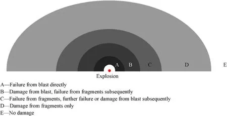
Fig.1.Zones of failure and damage from blast and fragments,where the failure represents that the penetrating fracture appears in the structure.
Lightweight structural design for ballistic protection based on metal-polyurea combinations is explored extensively over the years.The experimental works mainly focus on the layered structure and study the effect of configurations,polyurea content,and projectiles on the structural ballistic performance [6-10].Among them,the ballistic experiments performed by Mohotti et al.[11,12]show that the polyurea plays an important role in absorbing energy during both high-velocity and low-velocity impact.Roland and his group [9,13,14] care about the ballistic resistance of the polyureacoated steel plates to the fragments simulating projectiles (FSP)penetrating.They carry out systematic ballistic tests and investigate the effect of placement and thickness of coating,hardness and thickness of substrate.The results show that the plate with the front coating demonstrates a better performance than that with the back coating.They also propose that the impact-induced glass transition of polyurea is responsible for its strengthening to the structural ballistic resistance [3].Besides,other scholars study the ballistic resistant mechanisms of the polyurea-coated steel plate through numerical simulation.Xue et al.[8] and Liu et al.[15]investigate the strengthening mechanisms of polyurea on the ballistic performance of layered polyurea-steel structures by failure modes and energy absorption.Grujicic et al.[16]and Key et al.[17]simulate the ballistic limit tests conducted by Roland et al.[14].The results show that the dynamic strengthening of the polyurea and the stress wave propagation jointly lead to the coating placement effect on the structural ballistic resistance.Noteworthy,by developing a new viscoplastic constitutive model of polyurea considering the thermal and pressure effects,we study the strengthening mechanism and thickness effect of the coating on the ballistic resistance of the polyurea-coated steel plate numerically [18].The results show that increasing coating thickness can only provide the limited benefit for improving the ballistic resistance of the structure.
Recent studies also try to design the metal-polyurea structure to improve its blast resistance.Ackland et al.[19] and Mohotti et al.[20]adopt the maximum displacement of the steel plate to evaluate the structural blast resistance.The full-scale blast experiments of the former show that the polyurea-coated steel plate does not perform better than the bare steel plate with the same area density.Their numerical investigation illustrates that the debonding of the polyurea coating plays an important role in reducing the steel plate deformation and improving the structural blast-resistant performance.The specimen in the lab-scale or underwater blast experiments fails more commonly due to the higher load-thickness ratio.In this case,the investigation of Xue et al.[21-23] illustrates that the large-strain strengthening polyurea may synergize with the plastic-softening metal and delay its localized deformation and failure.However,this effect has not been proven effective in the dynamic process [24].The localized blast experiments of the layered polyurea-steel structure performed by Hou et al.[25]show that the placement of the polyurea affects the failure modes and energy dissipation of the steel plate,thus affecting the structural blast resistance consequently.Chen et al.[26] simulate these experiments and study the effects of the strength of steel,polyurea and interface.In the water-loading impact experiments conducted by Amini et al.[4,27],the impact resistance of the front-coating steel plate is lower than that of the back-coating plate,which is explained by the impedance matching theory.Until now,the structural design for the polyurea-coated steel plate considering both ballistic and blast resistance is still lacking.
The combined fragments and blast loading formed by the actual explosion can cause serious damage to the protective structures.Recently,some scholars focus on studying the characteristics of the combined loading and its damage effect on different structures.Nyström et al.[28] proposed a theoretical prediction of the arrival time of fragments and blast front to the striking target after explosion occurring,mainly taking into account the rapid attenuation of the blast wave.According to their prediction,the structures at different distances from the explosion center suffer from different impact loads and undergo different failure processes.As shown in Fig.1,the structure closest to the explosion center fails directly from the earlier-arriving blast wave.However,the structure slightly further away fails from fragments penetration firstly,then damages by blast impact.These features of the combined loading also appear in the field tests carried out by Grisaro et al.[29].Besides,the synergistic effect of the combined fragments and blast loading on protective structures is reported.The studies about the dynamic behaviors of the concrete under the combined loading show that the synergetic damage effects are much larger than the damage effect by individual actions of fragments and blast[28,30,31].Until now,scholars have studied the dynamic responses of the metal structures [32-34],multi-layered composite structures [35-37]and water-based protective structures [38] under the combined loading.However,the knowledge about the deformation and failure of the polyurea-coated steel plate under the combined fragments and blast loading is still limited.There is also no structural design for the polyurea-coated steel plate targeting its application in the combined loading.
In this paper,on the one hand,the polyurea-coated steel plate is designed considering both ballistic and blast resistance.The steelcore sandwich plates are proved to own outstanding comprehensive ballistic and blast resistance.The distribution diagram of ballistic and blast resistance for different polyurea-coated steel plates is given to guide the structural design in different explosion scenarios.On the other hand,the dynamic response of the designed plates under the combined fragments and blast loading is analyzed.The results show that the synergistic effect of the combined loading reduces both the ballistic and blast resistance of the polyureacoated steel plate.The acting sequence of the fragments and blast affects the structural protective performance heavily.When fragments impact first,the excellent unit-thickness ballistic performance of the structural front part is strongly needed for improving the comprehensive ballistic and blast resistance.
This paper is organized as follows.We begin by introducing the computational model and the index for evaluating the ballistic and blast resistance of the polyurea-coated steel plate in Section 2.Utilizing this model,the polyurea-coated steel plate with fixed area density is designed for improving its comprehensive ballistic and blast resistance in Section 3.Then,in Section 4,the dynamic response of the designed plates under two scenarios with combined fragments and blast loadings is investigated,and the structural form with better performance under the combined loading is discussed.At last,some meaningful results are given in the conclusions.
2.Computational model for evaluating the ballistic and blast resistance
In this section,the computational model using for evaluation is built and verified,referring to experiments.The basic setups of the model,including geometry,material and interface models,are introduced in Section 2.1.By providing the evaluating indexes,Sections 2.2 and 2.3 evaluate the blast and ballistic resistances of the polyurea-coated steel plates tested in the experiments individually and verify the computational model.
2.1.Computational model setups
The computational model for evaluating the ballistic and blast resistance of the polyurea-coated steel plate is constructed referring to the ballistic limit tests and localized blast experiments conducted by Roland et al.[14]and Ackland et al.[19],respectively.In the ballistic limit tests,the tested plates are penetrated by a 0.5 cal fragments simulating projectiles(FSP).This kind of projectile is suitable for simulating the threat of relatively large-size fragments produced during the explosion.On the other hand,localized blast experiments are carried out to simulate the threat from the blast wave generated by the near-field explosion.The air-blast load is applied by charging nominally 500 g pentolite spheres.The distance between the charge center and the striking surface of the tested plate is 51.5 mm.In these above experiments,the samples include bare steel plates and polyurea-coated steel plates with different configurations.
2.1.1.Description of the polyurea-coated steel plate model
By integrating the experimental settings,the geometric dimensions of the plates are selected as 700×700 mm2.Due to the symmetry of the problem,only half of the model is built.In experiments,the steel plate is clamped,which is represented by the fixed boundaries with all translational and rotational velocities setting as zero.The FSP is modeled according to the corresponding specification [39].Its tail is simplified,while a mass of 13.25 g is maintained.The typical geometry of the computational model is illustrated in Fig.2.The model is meshed with 8-node solid elements adopting first-order reduced integration.The FSP and the ballistic impact location of the steel plate and polyurea coating are meshed with a nominal edge length of 0.3 mm.Other regions staying away from FSP impacting are meshed with a lateral edge length of 3 mm.The dimension of these elements along the impacting direction is set to be less than 1 mm to ensure that steel plate and polyurea coating possess at least 6-layers elements in the thickness direction.The convergence of the mesh density is analyzed in Appendix C.In this research,the polyurea-coated steel plates are noted as PxSy to simplifying the description,where x and y represent the thickness of the polyurea coating(P)and steel plate(S)in millimeters,respectively.The order of P and S represents the material configuration of the structure from the striking surface to the back surface.
2.1.2.Steel material model
Two different kinds of steel materials are adopted in experiments.Both of them are modeled by the Johnson-Cook strength and failure model without considering the thermal effect[40].The material yield stress is described as:


with σmbeing the negative value of pressure,˙ε0being reference strain rate,and D1,D2,D3,D4being material-dependent parameters.The material property of armor steel employed in ballistic limits tests is similar to 4340 steel [17].Its volumetric response under ballistic impact is described by a Mie-Grüneisen equation of state(EOS)[41],and the pressure can be expressed by the volume change J as:

where ρ0is initial density,Γ0is the Grüneisen parameter,C0and S are the intercept and slope of the linear relationship between shock wave and particle speed respectively.e and e0are internal energy per mass at the current and initial state respectively.The failure parameters of Bluescope XLERPLATE 350 steel used in the localized blast experiments are not provided.Table 1 presents the material parameters of the above two kinds of steel.In the following sections,Bluescope XLERPLATE 350 steel is only applied to reproduce the near-field blast experiments.In other cases,the material of steel plate and FSP is set as 4340 steel.
2.1.3.Polyurea material model
The polyurea coating employed in the ballistic and blast experiments is made by an exemplar copolymer polyurea,PU1000.The dynamic behaviors of this material have been investigated widely through uniaxial large-strain loading and linear dynamic analysis [42-47].As shown in Fig.3(a),we test its uniaxial responses with different strain rates[18],and the dynamic stiffening and strengthening are striking.Clifton et al.[48] characterize the dynamic response of PU1000 under the pressure-shear plate impact.The results show that strongly volumetric stiffening and shear strength enhancement occur for the polyurea under the highpressure impact,seeing Fig.3(b).These dynamic properties of the polyurea are crucial for its application to impact protection.In particular,the impact-induced stiffening and strengthening for the material ahead of the FSP can provide significant resistance to the ballistic penetration.
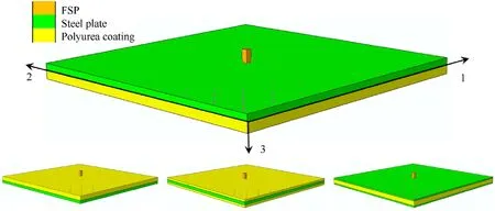
Fig.2.The quarter geometric model for evaluating the ballistic and blast resistance of the polyurea-coated steel plate,where the arrows on the upper surface of the plate represent the pressure loading generated by the blast.

Table 1 Material parameters for steel.
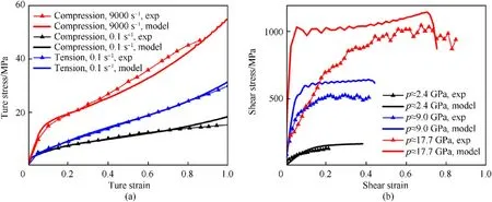
Fig.3.The dynamic behaviors of PU1000 obtained from experiments and numerical modeling: (a) the uniaxial compression and tension responses with different strain rates;(b)the shear behaviors under certain impact pressure,the experimental data in (b) is obtained from the pressure-shear plate impact experiments [48].
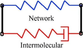
Fig.4.The viscoplastic constitutive model of polyurea consists of a network component and an intermolecular component.
The constitutive model of polyurea is built now to capture the main dynamic behaviors of polyurea under ballistic and blast impact,including the large-strain recoverability and the impactinduced stiffening and strengthening.As shown in Fig.4,it consists of a hyperelastic network component and a viscoplastic intermolecular component.They are responsible for describing the basic nonlinear large-deformation and the strain-rate sensitivity of polyurea,respectively.The shearing stiffening and strengthening under the high-pressure impact are mainly realized by strongly volume-dependent shear modulus and viscoplastic flow.
The large deformation kinematics of the present constitutive model is defined firstly.The terms relating to the network component and the viscoplastic intermolecular component are given by a subscript “N” or “I”,respectively.The total deformation gradient F is multiplicative split into elastic(e)and viscoplastic(vp)parts,F=FeN=FeIFvpI.The left Cauchy-Green tensors in two components are defined as BeN=FeNFeTNand BeI=FeIFeTI.The volume change J is equal to the determinant value of F.The velocity gradients for the intermolecular component is decomposed into:

where LeIandcan be regarded as elastic and viscoplastic deformation rate,respectively.includes the symmetric and the skew part,representing the stretching and spin rate of the viscoplastic deformation,respectively.
The Cauchy stress is divided into bulk part and deviatoric part,and the latter includes the network component and the intermolecular component.

To capture the nonlinear volumetric response under the highpressure impact,a Lennard-Jones type volumetric free energy is employed [42].The pressure is given as:

where K is the bulk modulus.
The stretching and rotation of the network are described by the Arruda-Boyce eight-chain elasticity model [49],and the deviatoric Cauchy stress is:

To capture the significant hysteresis of polyurea deformation under low strain rates,a phenomenological evolution model for the shear modulus and limiting chain extensibility of the network is given as [42]:

with subscript“0”representing the initial values.It can describe the limiting chain extensibility increases as the network crosslinks breakdown.The orientation parameter α can provide a quantitative assessment of the topological alignment of molecular chains under deformation [42,50],which is defined as:

with λibeing the principal stretches of the network.It is taken as the basic variable to describe the softening rules of the shear modulus:

where the exponent q controls the softening rate,α0is the initial orientation parameter without deformation.The instantaneous modulus at the unloading state is assumed to be equal to its initial value according to the stress-strain response of polyurea under unloading [42].
The intermolecular component is taken to follow a Neo-Hookean formulation [51]:


with no loss on generality,the viscoplastic flow is assumed to be irrotational and co-axial to the deviatoric stress tensor,then,

Impact-induced shearing strengthening is realized by the pressure-dependent viscoplastic flow.The pressure effect on the viscosity of the polymers is generally linked with a pressuredependent free volume fraction f,representing the free space for segments relaxation.Referring to Doolittle [53] relating the equivalent time of viscous flow to free volume fraction,the viscoplastic flow related to shear stress is given as:

where fris the free volume fraction under ambient pressure,is a reference flow rate,is the magnitude of the deviatoric stress,τ0is a reference shear strength,n is the rate sensitivity exponent.The orientation parameter α is taken as a variable to describe the dependency of viscosity on the chains orientation.
Under the high-pressure impact,the considerably volumetric deformation can result in the variation of free volume fraction,which is noted as ΔfJ.Then,

The volumetric free energy employed in Eq.(6) means that the volumetric response is assumed isentropic.Thus,ΔfJis related to the isentropic volume change.The explicit relationship between ΔfJand J is determined by fitting the results of pressure-shear plate impact experiments using a quadratic polynomial equation iJ2-jJ+j-i,which introduces parameters i and j.
The details of the parameter identification of the viscoplastic constitutive model are introduced in Appendix A.Table 2 lists the determined parameters of PU1000.The fitting results of the model to the material behaviors in uniaxial loading tests and pressureshear plate impact tests are shown in Fig.3.Obviously,the stressstrain trends can be captured reasonably.
The polyurea failure is modeled by elements deletion without considering damage evolution.The maximum principle stretch λmax=(Ui), U=(FFT)1/2is taken as the basic variable to determine the state of the material.The critical failure value of λmaxis set as 3.0 [16].
In order to simulate the debonding between polyurea coating and steel plate,a 0.2 mm thick bonding layer is added between the two materials.The bonding layer is assumed to have the same deforming properties as polyurea while having a similar failure criterion as the cohesive model.Its failure is modeled by elements deletion following the maximum strain criterion without damage evolution.The critical failure strains along two orthogonal directions in the bonding plane and normal directions of the bonding plane are noted as εc1,εc2and εc3,respectively.Their values are determined according to the debonding process of the polyurea coating in the localized blast experiments.
2.2.Blast resistance evaluation
2.2.1.Blast loading applying
The blast loading is firstly applied by the CONWEP function provided by ABAQUS.The CONWEP function describes the fluid/structure interaction approximately.It calculates the pressure load applying to the structure surface based on the equivalent mass of TNT and the blast wave propagation regulation.To alleviate the weakness of the CONWEP function in reproducing the near-field air-blast loadings,we adapt the pressure magnitude factor of the CONWEP function and try to realize a better fitting betweenexperimental and numerical loading.This method of modifying the CONWEP function is proposed and verified by Long`ere et al.[54].It can be drawn from their work that this method is not so sensitive to the distance between the explosive center and the plate.Thus,using a fixed pressure magnitude factor here is feasible.In this way,the dynamic response of the 6 mm thick bare plate(S6) in experiments is firstly simulated.The equivalent TNT coefficient of pentolite is set as 1.114 [55].As shown in Fig.5(a),determining the pressure magnitude factor as 1.3 can make the final residual deformation of S6 obtained from experiment and simulation basically consistent.
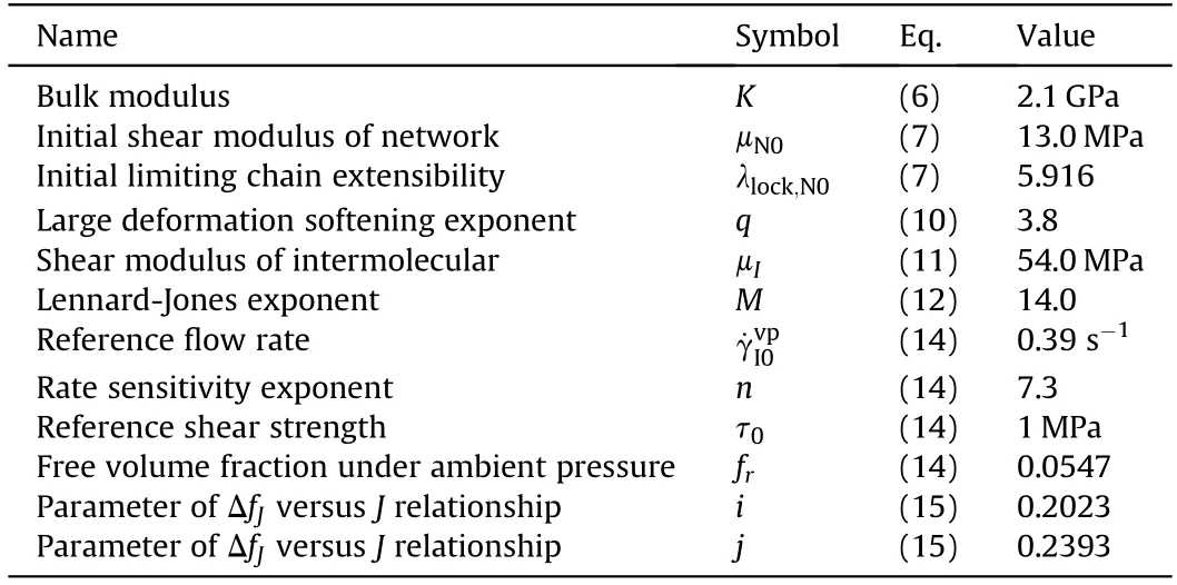
Table 2 Material parameters for PU1000.
After obtaining the numerical applying of blast loading,the dynamic response of S5P7.7 under this loading is simulated to determine the failure parameters of the debonding layer.By comparing the debonding process and residual debonding area of the polyurea coating appearing in experiment and simulation,the critical failure strains of the debonding layer are taken as εc1=εc2=0.1 and εc3=0.05.The residual deformation of the plate and the dynamic response of the polyurea coating are shown in Fig.5(b),(c) and Fig 6.The agreements between experimental and numerical results are obvious.
For the front-coating plates,the large deformation of the polyurea coating due to its relatively low modulus makes applying loading through the CONWEP function in ABAQUS difficult.The blast loading calculated by the CONWEP function is substituted by an equivalent pressure load varying with time and space in the subsequent simulation.Its formulation is determined according to the variation and distribution of the pressure load on the striking surface of S5P7.7.The impulse of each loading point is ensured to be constant before and after load equivalency.The details about this operation are shown in Appendix B.Fig.5(b) and (c) present the simulating results adopting the equivalent pressure load,which are agree with the results before load equivalency.It is worth noting that the blast generated by the same charge acts with different pressure loads on different structures with the same explosive distance,which results from the diverse deforming process of the structures.However,this difference has a minor effect on the structural design remaining constant area density since the structural modulus does not vary widely in this case.
2.2.2.Blast resistance evaluation
The historic maximum displacement of the steel plate is selected as the index to evaluate the structural blast resistance according to the localized blast experiments[19],which can reflect the reusability of the structure and the safety of the functional devices attached to the steel plate in practical applications.Adopting this index,the blast resistance of the bare steel plates and back-coating plate with the same area density is evaluated referring to experiments.Fig.6(b) presents the dynamic response of S5P7.7 at 0.8 ms after blast occurring,where large deformation of the steel plate and debonding of the coating appear around the blast location.As shown in Fig.6(c) and(d),the debonded coating rebounds and forms a circular residual debonding area at the later stage of structural response.The large-area debonding makes a large amount of impact energy transform to the internal energy of the coating,reducing the deformation and damage of the steel plate and improving the structural blast-resistant performance.Fig.7(b)compares the blast resistance of different plates tested by experiments and simulation.The experimental data is substituted with the maximum residual displacement of the steel plate,which is acceptable due to the dominance of the plastic deformation.The results show that the evaluating model can predict the blast resistance of the polyurea-coated steel plate reasonably.
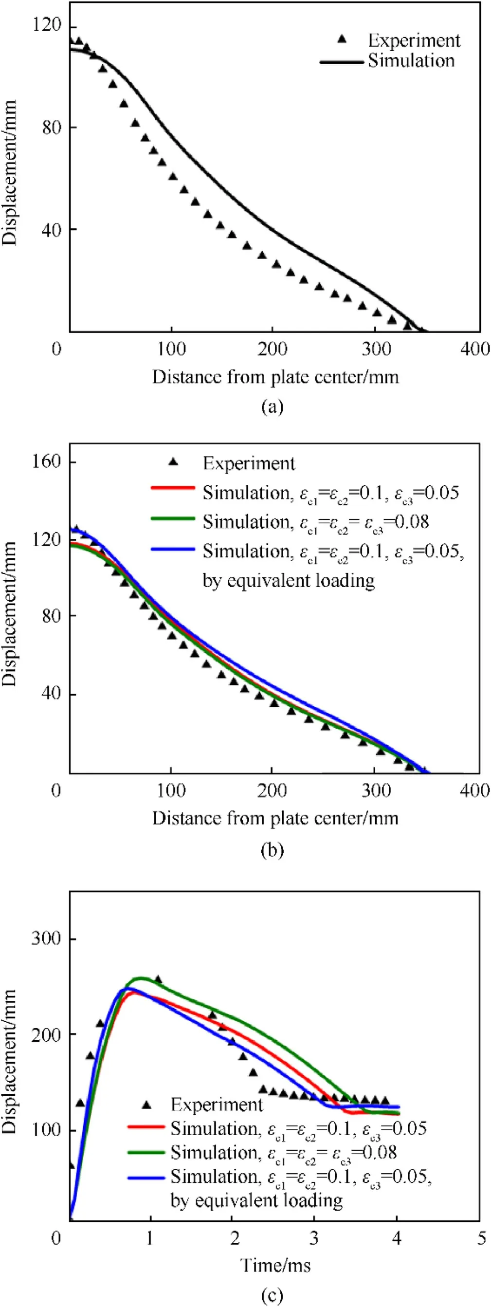
Fig.5.The residual deformation of the steel plate for (a) S6 and (b) S5P7.7;(c) The displacement history of the back center of the polyurea coating for S5P7.7.The experimental data is obtained from the localized blast tests [19].
2.3.Ballistic resistance evaluation
The structural ballistic resistance is evaluated by the ballistic limit V50,the critical penetrating velocity of FSP towards the structure.It is determined using a similar method as it used in experimental tests,taking the average of the lowest velocity that penetrates the target and the highest velocity that does not.The two velocities cannot differ by more than 5 m/s in our simulations.The ballistic resistance of the 5.1 mm thick steel plates front-coated with different-thickness polyurea layers is evaluated to verify the evaluating model,referring to the experiments [14].The dynamic response of P2.8S5.1 at 120 μs after FSP impacting with 920 m/s is shown in Fig.6(a).The structural response time under ballistic penetrating is much shorter than that under blast loading.The area with large deformation and failure is also more concentrated for the former,mainly at the penetrating location.This reflects different ballistic and blast damage mechanisms,which bring challenges for designing protective structures with excellent comprehensive ballistic and blast resistance.Fig.7(a)compares the V50 of different plates obtained from experiments and simulation.It can be seen that the computational model for evaluation can capture the ascending trend of structural ballistic resistance with increasing coating thickness rightly.
3.Designing the polyurea-coated steel plate
In this section,the polyurea-coated steel plate with fixed area density is designed to improve comprehensive ballistic and blast resistance.To achieve this goal,the thickness effects of the polyurea coating on structural ballistic and blast resistance are studied firstly in Section 3.1.After that,the steel-core sandwich plates are designed in Section 3.2 by combining the placement and thickness effects of the coating,which are proved to own outstanding comprehensive ballistic and blast resistance.
3.1.The thickness effects of the polyurea coating on ballistic and blast resistance
According to previous experimental and numerical investigations[9,14,17],coating polyurea on the impact face has more significant contributions to promoting the structural ballistic resistance for the steel plate with single surface coating.This results from the significant enhancement of the pressure and shear strength of polyurea under extreme compression.On the other hand,coating polyurea on the back face improves the structural blast resistance more considerably.It is attributed to the reduction of impact energy transformed to the steel plate due to the debonding of the coating [19].Besides the placement effects,the thickness effects of the coating also need to be studied to design the polyurea-coated steel plate with as high comprehensive ballistic and blast resistance as possible under the fixed area density constraint.
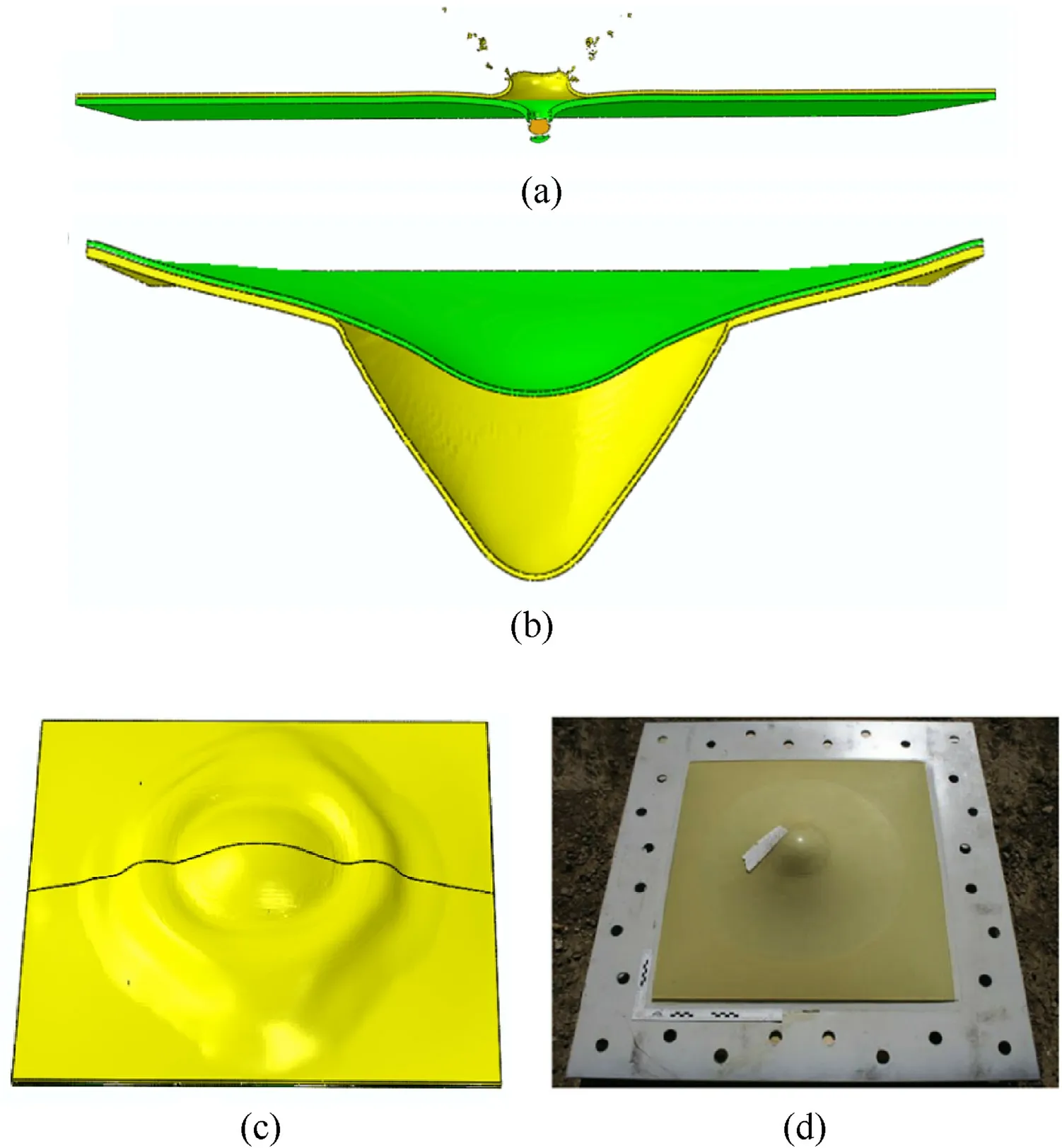
Fig.6.(a)The dynamic response of P2.8S5.1 at 120 μs after FSP impacting;(b)The dynamic response of S5P7.7 at 0.8 ms after blast occurring;The residual debonding area of S5P7.7 after suffering from blast impacting obtained from (c) simulation and (d) experiment [19].
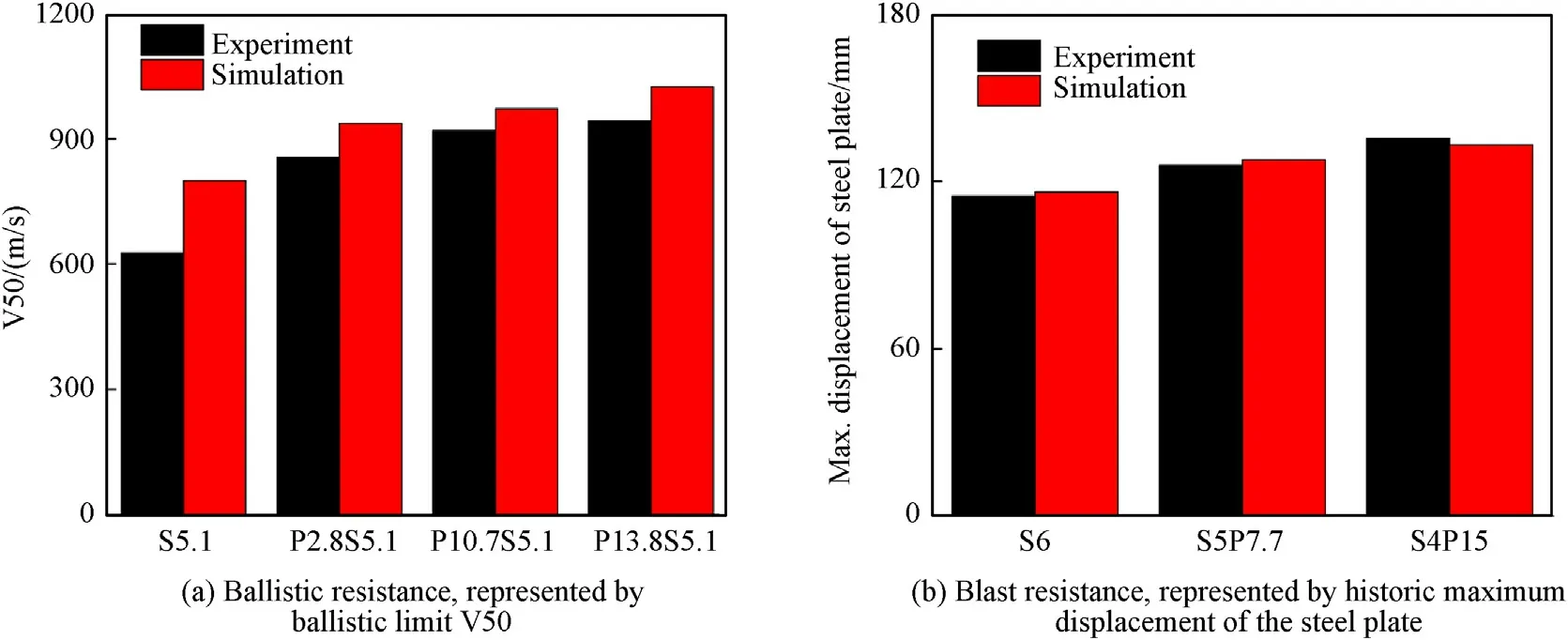
Fig.7.Ballistic and blast resistance of the plates obtained from experiments [14,19] and simulation.
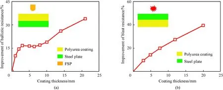
Fig.8.(a)The ballistic resistance improvement of the 5 mm thick steel plate after front-coating different-thickness polyuria;(b)The blast resistance improvement of the 5 mm thick steel plate after back-coating different-thickness polyurea.
Therefore,the ballistic resistance improvement of the 5 mm thick steel plate after front-coating different-thickness polyurea is simulated,and the results are shown in Fig.8(a).Apparently,the structural ballistic resistance does not increase linearly with coating thickness.Especially,the strengthening efficiency of the polyurea coating on the structural ballistic resistance reduces greatly when the coating is thicker than 3 mm.This illustrates that increasing coating thickness continuously can only provide the limited benefit for improving the ballistic resistance of the structure.Notably,the thickness turning point,3 mm,can vary with the geometry of FSP and steel plate,and the FSP velocity.These phenomena result from the combined effect of the dynamic strengthening of the polyurea and the shock wave propagation [18].
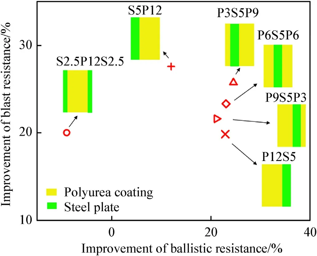
Fig.9.The distribution diagram of ballistic and blast resistance for different polyureacoated steel plates.
In addition,the blast resistance improvement of the 5 mm thick steel plate after back-coating different-thickness polyurea is studied.The blast loading applied is the same as it introduced in Section 2.In this case,the steel plates of the structures with the thin coating will fail under blast impact.However,the failure of the steel plates is not taken into account temporarily because we just need to obtain the structural blast resistance index,the historic maximum displacement of steel plate,varying with coating thickness to guide the structural design.The results are presented in Fig.8(b).It can be seen that the structural blast resistance constantly increases with the coating thickness.This results from increasing energy stored and dissipated in the debonded polyurea.
3.2.Structural design with fixed area density
Have obtained the placement and thickness effects of the coating on the ballistic and blast resistance,the polyurea-coated steel plate can be designed to improve comprehensive ballistic and blast resistance.As for ballistic protection,coating polyurea on the front surface of the steel plate is more beneficial.However,increasing coating thickness continuously can only provide the limited benefit for improving the ballistic resistance.For example,for the 5 mm thick steel plate,the strengthening efficiency of the coating drops greatly when it is thicker than 3 mm.Thus,the extra polyurea can be coated on the back surface of the steel plate to improve the blast resistance more effectively.According to this design method,the steel-core sandwich plate may possess higher comprehensive ballistic and blast resistance.To test the effectiveness of this design method,the ballistic and blast resistances of different polyurea-coated steel plates with fixed area density are evaluated individually.The total thicknesses of the steel plate and polyurea coating are limited to 5 and 12 mm,respectively.The structural configurations include front-coating plate(P12S5),backcoating plate (S5P12),polyurea-core sandwich plate(S2.5P12S2.5)and steel-core sandwich plates with different coating strategies(P3S5P9,P6S5P6 and P9S5P3).
Fig.9 presents the improvements of the ballistic resistance and the blast resistance of these plates compared with the 5 mm thick bare steel plate.It can be seen that only the polyurea-core sandwich plate S2.5P12S2.5 possesses a lower ballistic resistance compared with S5.The reason for it is that dividing the steel plate significantly reduces its ability to erode FSP.Besides,the blast resistance of S2.5P12S2.5 is also not outstanding since the bending stiffness of the steel plate decreases greatly after being divided.For other plates,their blast resistance is related to the thickness of the back coating.This illustrates the back coating has an absolute advantage in promoting the structural blast resistance compared with the front coating.However,the advantage of the front coating in improving structural ballistic resistance is not so prominent.The numerical results show that the back coating can also play an important role in anti-penetration when it is thick enough.Thus,P3S5P9 has the highest ballistic resistance among these plates.
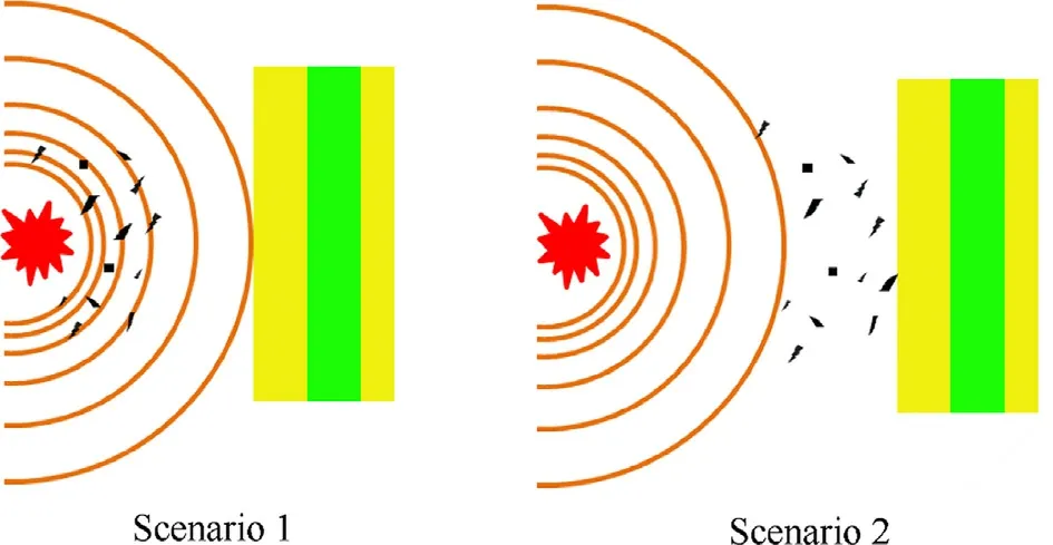
Fig.10.Two combined loading scenarios caused by the explosion: Scenario 1 blast wave acts on structure firstly;Scenario 2 fragments impact structure firstly.
Notably,no polyurea-coated steel plate in Fig.9 owns both the highest ballistic and blast resistance.However,Fig.9 shows us the distribution of ballistic and blast resistance for different plates,which can be utilized to guide the design of protective structures applying in different explosion scenarios.For example,P3S5P9 should be adopted when fragment-proof is valued,while S5P12 can be adopted in the scenario where blast protection is more important.Both P3S5P9 and S5P12 own excellent comprehensive ballistic and blast resistance.
4.Dynamic response analysis under combined fragments and blast loading
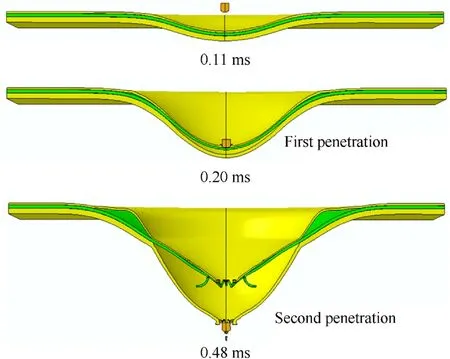
Fig.11.The dynamic response of P3S5P9 in Scenario 1.The two penetrations refer to FSP penetrating the structural components except the back coating and penetrating the debonded back polyurea coating.
This section studies the dynamic response of polyurea-coated steel plates designed in Section 3.2 under two scenarios with combined fragments and blast loading.The scenarios are setting according to the actual explosive occurrence,which generates both fragments and blast waves.Typically,the blast wave propagates with a higher initial velocity while it decays faster.On the other hand,the flying velocity of the fragments declines more slowly.Thus,the structures at different locations can suffer from different loading scenarios where the acting sequences of fragments and blast loading are just opposite.This leads to different failure processes of the structures,seeing Fig.1.The two scenarios studied in this section are blast wave acting firstly and fragments impacting firstly,respectively,as shown in Fig.10.Notably,in Fig.1,the dynamic response of the structures in zone B and C is more complicated and worthy of analysis compared with the structures in other zones.To make the structural failure in the two scenarios locate at zone B and C in Fig.1 respectively,the initial velocity of FSP is set as 800 m/s,and the blast loading is set slightly weaker than that applied before.Then,the blast loading applied before multiplying an amplitude factor 0.8 is adopted in this section.Since the explosion is not modeled by the fluid/structure coupling method,the interaction between the fragment and blast wave cannot be considered here.The two scenarios are realized by changing the initial distance between FSP and plate.The comprehensive ballistic and blast resistance of four plates designed in Section 3.2 is evaluated.
4.1.Results in scenario 1
For Scenario 1,the initial position of FSP is set as 80 mm away from the plate along the impact direction.The typical dynamic response of the steel-core sandwich plate in this scenario is presented in Fig.11.The plate suffers from blast impacting firstly.Large plastic deformation of the steel plate and debonding of the back coating occurs at this stage.After the FSP catches up with the motion of the plate,penetrating starts.The failure process of the plate is located at zone B in Fig.1 exactly.Due to the debonding,the FSP has two penetration and deceleration processes while impacting the back-coating steel plates,which are marked in Fig.11.
The original evaluating index of structural blast resistance is not valid because of the failure of the steel plate.Here,the remaining velocity of FSP and the failure modes of the steel plate are investigated to evaluate structural comprehensive ballistic and blast resistance.Fig.12(a) compares the velocity reduction of FSP in different stages when it penetrates the four plates.Apparently,the anti-penetrating capability of the plate is related closely to its blast resistance shown in Fig.9.The better blast-resistant performance of S5P12 makes its steel plate undergo less plastic deformation before the FSP penetrates,which is advantageous to its subsequent resistance to FSP.Since the FSP penetration occurs at the latter stage of steel plate response,there is no large-area breaking of the steel plates in this scenario,seeing Fig.12(b).From above,the S5P12 has the best comprehensive protective performance among the four plates in this scenario.
4.2.Results in scenario 2
For Scenario 2,the initial position of FSP is set as 20 mm away from the plate along the impact direction.The typical dynamic response of the steel-core sandwich plate in this scenario is presented in Fig.13.Initially,the plate mainly suffers from FSP penetrating.As the plate constantly accelerates and deforms under the blast loading,the decelerated FSP separates gradually from the plate.After that,the plate continues to deform and debond under the blast impact.When the steel plate deformation slows down in the later stage of the blast loading,the FSP has the opportunity to impact the structure again.Then,the steel plate and the debonded back coating are penetrated individually,seeing the last two snapshots of Fig.13.From above,the FSP has three penetration and deceleration processes while impacting the back-coating steel plates,including FSP impacts the plate for the first time,penetrates the structural components except the back coating and penetrates the debonded back polyurea coating.They are marked in Fig.13.The failure process of the plate is located at zone C in Fig.1 exactly.
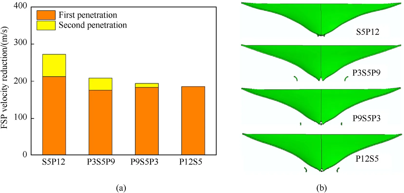
Fig.12.(a) The velocity reduction of FSP during two penetrations in Scenario 1;(b) The failure modes of the steel plate for different structures in Scenario 1.
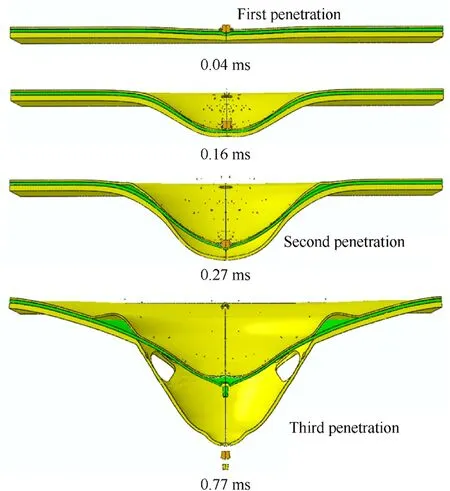
Fig.13.The dynamic response of P3S5P9 in Scenario 2.The three penetrations refer to FSP impacting the plate for the first time,penetrating the structural components except the back coating and penetrating the debonded back polyurea coating.
Fig.14(a) presents the velocity reduction of FSP in different stages when it penetrates the four plates.It can be seen that the velocity reduction during FSP first impacts different plates does not match the structural ballistic resistance shown in Fig.9.This can be explained as that the first penetration mainly tests the unitthickness ballistic performance of the structural front part,which is related to the structural dynamic stiffness and strength of the front part.In this case,S5P12 and P3S5P9 have advantages.For the second penetration of FSP,its velocity reduction is mainly related to the damage degree of the steel plate before this penetration starts.Because of serious damage from the direct impact of FSP during the first penetration,the steel plate of S5P12 almost loses the ballistic resistance in this stage.In contrast,P12S5 is just the opposite.For the third penetration,the thicker back polyurea coating and the lower remaining velocity are helpful to the velocity reduction of FSP.
The failure modes of the steel plate for different structures are shown in Fig.14(b).Notably,the steel plate of S5P12 shows the most serious failure under the combined loading,even though it has the best performance under the single blast loading.This illustrates that the structural blast resistance is influenced heavily by its ballistic performance in Scenario 2.In addition,the remaining velocities of the FSP after penetrating S5P12 and P9S5P3 are in small difference,indicating that the structural blast-resistant performance can also influence the ballistic resistance.Taken together,the synergistic effect of the combined fragments and blast loading on the polyurea-coated steel plate is significant.The S3P5S9 has the best comprehensive protective performance among the four plates in this scenario.
4.3.Discussion
As shown in Fig.1,except for staying very close to or far from the explosion center,the protective structures fail or damage under the combined fragments and blast loading when suffering from explosion impacts.However,the dynamic response of the polyureacoated steel plate is extremely complex under the combined loading.The synergistic effect of the combined fragments and blast loading on the polyurea-coated steel plate is significant.By comparing the results of Section 4.1 and 4.2,it can be drawn that the blast loading reduces the structural resistance to fragments penetrating,and the fragments loading also reduces the structural blast resistance.The failure caused by the combined loading is more severe than the sum of the failures caused by the individual fragments and blast impact.For example,the significant petal fracture of the steel plate for S5P12 occurs in Scenario 2,which does not occur under the original single ballistic or blast loading.
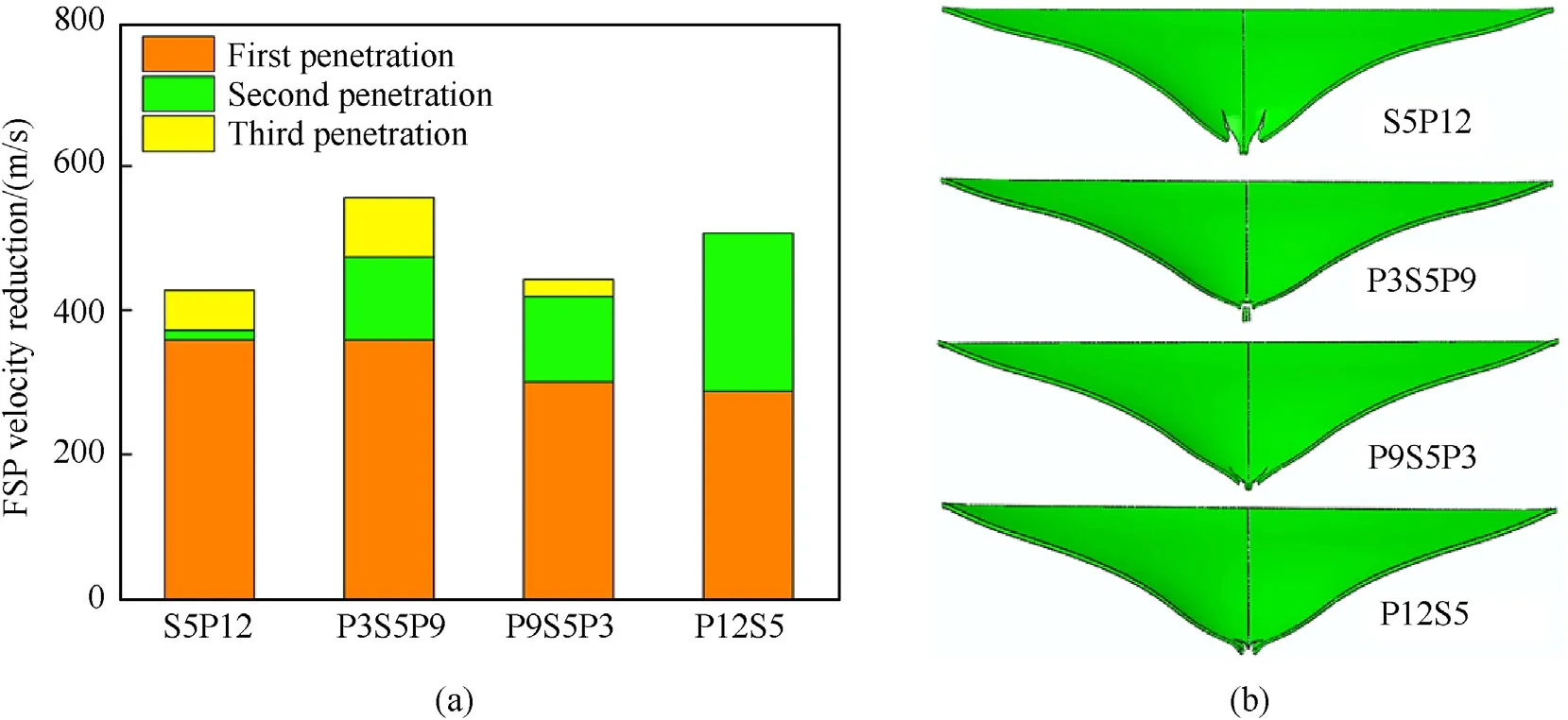
Fig.14.(a) The velocity reduction of FSP during three penetrations in Scenario 2;(b) The failure modes of the steel plate for different structures in Scenario 2.
On the other hand,the acting sequence of the fragments and blast affects the structural protective performance heavily under the scenario with combined loading.According to the above numerical results,the first loading inducing large deformation or damage generally is dominant.It is important to define which loading is dominant before determining the structural form of the polyurea-coated steel plate in the actual application scenario.After that,the structural form can be selected referring to Fig.9,the distribution diagram of ballistic and blast resistance for different polyurea-coated steel plates.However,Fig.9 can just provide a guide due to the complexity of the structural dynamic response under the combined loading.The optimal structural form needs to be determined eventually according to the actual dynamic response process.For example,the plate with outstanding comprehensive ballistic and blast resistance in Scenario 2 also strongly needs excellent unit-thickness ballistic performance of the structural front part.
5.Conclusion
The impact resistance of polyurea-coated steel plate under complex dynamic loading is analyzed and designed for improving comprehensive ballistic and blast resistance using the established computational evaluating model in this paper.The thickness effects of the polyurea coating on the impact resistance are studied first.According to the thickness and placement effects of the coating,the steel-core sandwich plates owning outstanding comprehensive ballistic and blast resistance are designed.The distribution diagram of ballistic and blast resistance for different polyurea-coated steel plates is also given to guide the design of protective structures applying in different explosion scenarios.
In addition,the dynamic response of the polyurea-coated steel plate under two scenarios with combined fragments and blast loading is investigated.The results show that the combined loading has a significant synergistic effect on the polyurea-coated steel plate.It reduces both the ballistic and blast resistance of the plate and causes more severe failure under the combined loading than the sum of the failures induced by the individual fragments and blast impact.The acting sequence of the fragments and blast affects the structural protective performance heavily.It is found that the first loading inducing structural large deformation or damage generally is dominant.When fragments penetrate first,the excellent unit-thickness ballistic performance of the structural front part is strongly needed for improving the comprehensive ballistic and blast resistance of the plate.The analysis of dynamic response and structural design for the polyurea-coated steel plate in this paper will help design the lightweight protection structures with excellent comprehensive ballistic and blast resistance.
Declaration of competing interest
The authors declare that they have no known competing financial interests or personal relationships that could have appeared to influence the work reported in this paper.
Acknowledgments
This work is supported by the Science Challenge Project,No.TZ2018002,National Natural Science Foundation of China,under Grant No.11972205,11972210 and 11921002,the National Key Research Development Program of China (No.2017YFB0702003).
Appendix A.Parameters identification of the constitutive model of polyurea
In our previous work[18],the uniaxial compressive responses of PU1000 with different strain rates are tested through universal testing machines and split-Hopkinson bars.The experimental results are shown in Fig.A1(a).Besides,the quasi-static uniaxial compression and tension by intermittent loading are also conducted to test the approximate time-independent stress-strain response,equilibrium state,of PU1000.As shown in Fig.A1(b),it is obtained by connecting the experimental data points after stress relaxation.
Since the network is assumed time-independent,the parameters of the network component can be identified according to the stress-strain relation of the equilibrium state.The Arruda-Boyce eight-chain elasticity model can capture the asymmetric elasticity of compression and tension naturally.Both the compressive and tensile equilibrium curves have two stages: the small-strain stage and the large-strain stage.The initial shear modulus μN0is identified according to the small-strain stage,while the λlock,N0is identified according to the large-strain stage.The softening exponent q is determined to describe the transition between the above two stages more accurately.The results of fitting stress-strain curves of the equilibrium state are shown in Fig.A2(a).
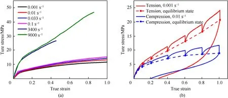
Fig.A.1.The experimental stress-strain curves for (a) uniaxial compression with different strain rates.and (b) uniaxial intermittent tension and compression.
The parameters of the intermolecular component without considering pressure effect are identified through the uniaxial compressive stress-strain curves with different strain rates.The shear modulus μItakes the initial modulus under 9000 s-1strain rate subtracting μN0.To determine the parameters of the viscoplastic flow rule,Eq.(14) is written as:

without considering pressure effect,where η=τ/is viscosity.Reference shear strength τ0is set as 1 MPa here.Then,the parameters n andcan be determined by fitting the linear relationship of log(α·η) with logat different strains.The fitting curves are presented in Fig.A2(b).
The parameters related to the pressure effect are identified according to the dynamic response of PU1000 in pressure-shear plate impact experiments [48],and the experimental results are presented in Fig.3(b) and Fig.A4.The bulk modulus of PU1000 is determined firstly according to its initial shear modulus and Poisson’s ratio[42].An impact-induced shearing strengthening factor is defined as the ratio of instantaneous shear strength to the shear strength under ambient pressure.The latter is about 15 MPa for shear strain rate at 105s-1to 106s-1,drawn from Fig.A1(a).According to the stress-strain curves of pressure-shear plate impact experiments [48],it is found that the shear strength (or the shearing strengthening factor) is roughly linear with the impact pressure.This linear relationship is fitted in Fig.A3(a).
It can be drawn from the above formulation of the constitutive model for polyurea that the intermolecular component is responsible for the shearing strengthening under strong impact.The effect of isentropic compression on the viscoplastic flow mainly causes the increasing of the shearing strengthening factor.Thus,the relationship of ΔfJversus J can be obtained according to volumetric response and the linear relationship of the shearing strengthening factor versus impact pressure.The free volume fraction under ambient pressure fris regarded as an inherent constant of the material here,and its value is taken referring to previous material characterization[18,46].Then,the data points of the ΔfJand J can be obtained,and their relationship is fitted by a quadratic function,seeing Fig.A3(b).At last,experiments 404,1201,and 1303 are simulated,where the geometry and material parameters of the metal plates are set referring to the experimental settings[48].The Lennard-Jones exponent M is determined by fitting the shear stress-strain curves,including instantaneous shear modulus and shear strength.The comparison of the numerical and experimental results for the pressure-shear plate impact tests is shown in Fig.3(b) and Fig.A4.Obviously,the dynamic response of polyurea under the high-pressure impact can be captured reasonably through this viscoplastic model.
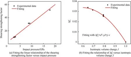
Fig.A.3.Determining the parameters related to the pressure effect.
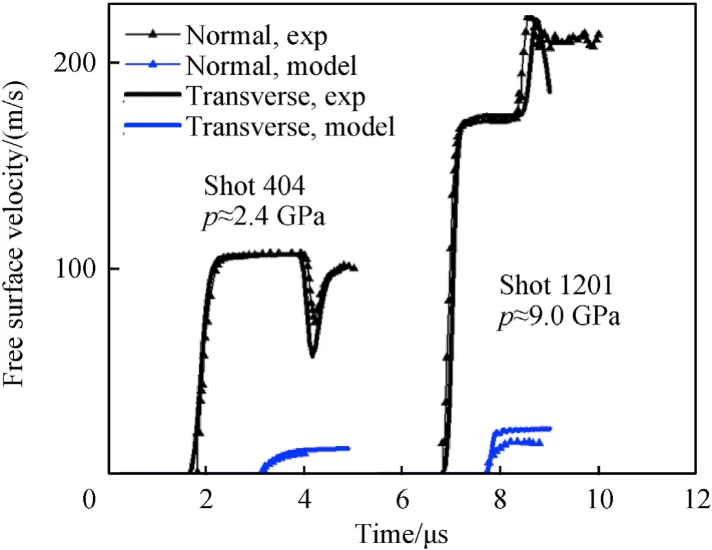
Fig.A.4.Comparing numerical and experimental [48] results for the normal and transverse velocity of the plate back free surface in pressure-shear plate impact tests.
Appendix B.Equivalent pressure load
The formulation of the equivalent load is determined according to the blast load of S5P7.7 calculated by the CONWEP function in ABAQUS.The pressure-time curves at different locations on the striking surface of S5P7.7 calculated by the CONWEP function are shown in Fig.B1(a).It can be seen that the time difference of the blast wave acting on different points is not obvious relative to the whole loading process,while the difference in the pressure amplitude variation is significant.The pressure-time curve at central point 0 basically conforms to the classic blast wave pressure equation.It declines quickly after attaining the peak.However,at the points staying away from the plate center,the pressure decreases slowly even forms a platform.This results from the continuous variation of the angle between striking surface and blast inputting direction with the further deformation.Considering that the blast loading time is relatively short compared with the response time of the entire structure,we assume the pressure-time curves at the points of the striking surface have the same shape as that on the central point 0.This leads to a simpler description of the equivalent loading.
From above,the equivalent pressure loads on other points can be expressed by multiplying an amplitude factor to the pressuretime curve on the central point 0.To ensure the equivalent effect of the blast loading,the impulse of each loading point is kept constant before and after load equivalency.Thus,the impulse area density ratio Im/Im0varying with the distance to the plate center x is firstly calculated by integrating the pressure-time curve on different locations,as shown in Fig.B1(b).This ratio is equal to the pressure amplitude factor,and it can be fitting well using the expression:

After that,the equivalent pressure loads on different points can be derived,seeing Fig.B1(c).The numerical results obtained by applying the equivalent pressure load are compared with those obtained using CONWEP loading in Fig.5(b) and (c).The agreements illustrate the reasonability of the equivalent loading.
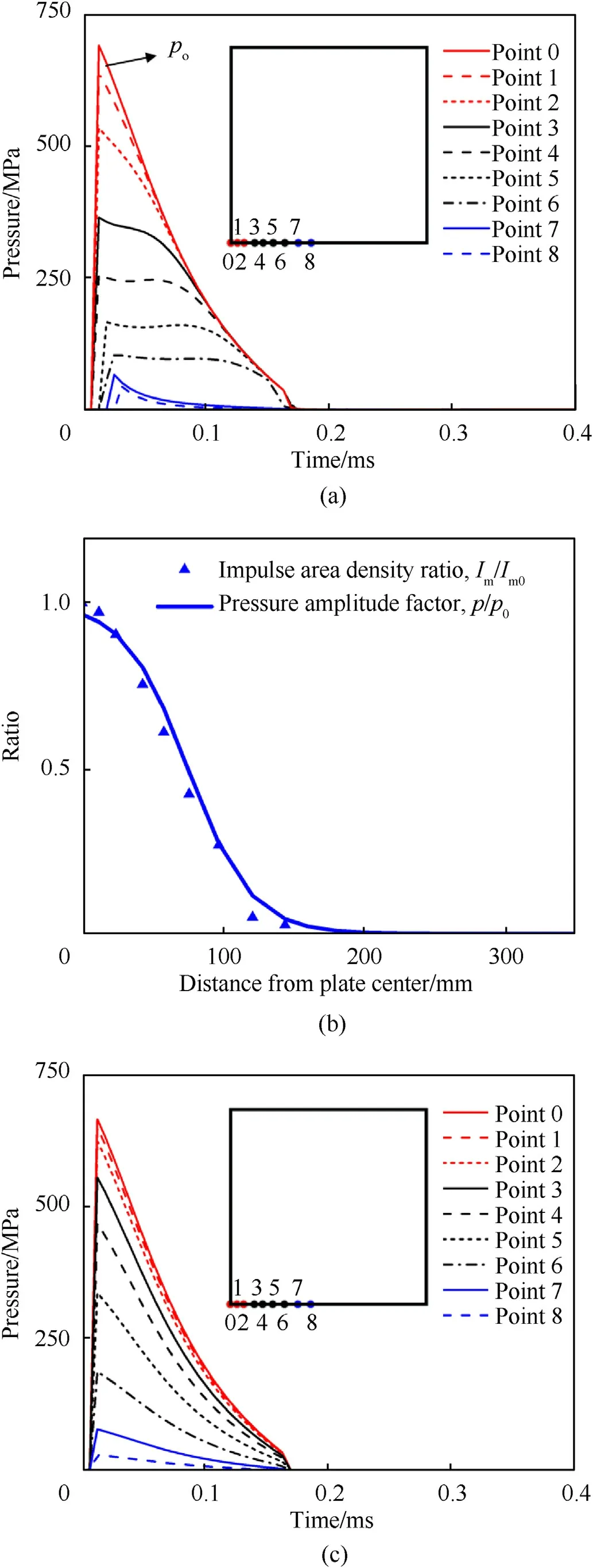
Fig.B.1.(a)The pressure loads at different locations on the striking surface of S5P7.7 calculated by the CONWEP function in ABAQUS;(b)The pressure amplitude factor varying with location is obtained by fitting the variation of impulse area density ratio;(c) The equivalent pressure loads at different locations on the striking surface of S5P7.7.
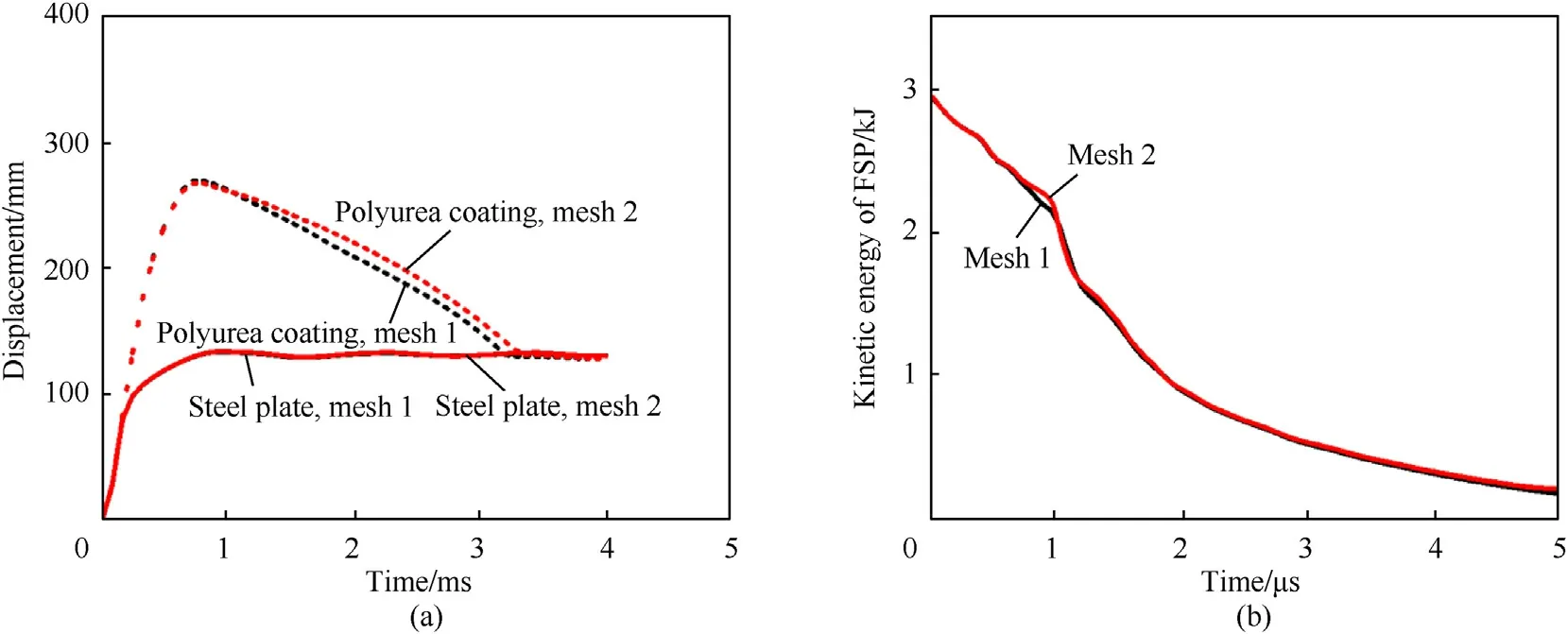
Fig.C.1.Comparing the numerical results using two different mesh strategies:(a)the displacement history of S5P7.7 under blast impact;(b)the kinetic energy history of FSP when it ballistic penetrates P2.8S5.1.
Appendix C.Influence analysis of mesh density
The mesh used for calculation is set as follows.The FSP and the ballistic impact location of the steel plate and polyurea coating are meshed with a nominal edge length of 0.3 mm.Other regions staying away from FSP impacting are meshed with a lateral edge length of 3 mm.This mesh strategy is called “mesh 1” here.Now,we increase the mesh density by meshing the ballistic impact location of the polyurea coating with a nominal edge length of 0.15 mm and meshing other regions staying away from FSP impacting with a lateral edge length of 2 mm.This finer mesh strategy is named “mesh 2”.The dynamic responses of P2.8S5.1 under the ballistic impact and S5P7.7 under the blast impact introduced in Section 2 are simulated adopting the above two mesh strategies.The displacement histories of polyurea coating and steel plate are taken to evaluate the accuracy of the model to simulate structural dynamic response under blast impact.The kinetic energy history of FSP is selected to test the accuracy of the model to simulate ballistic impact.The numerical results using different mesh strategies are compared in Fig.C1.It can be seen that the above two mesh strategies have few effects on the numerical results.The mesh sizes determined in this paper have convergence.
杂志排行
Defence Technology的其它文章
- Experimental and numerical analysis on suitability of S-Glass-Carbon fiber reinforced polymer composites for submarine hull
- Damage response of conventionally reinforced two-way spanning concrete slab under eccentric impacting drop weight loading
- Positive effects of PVP in MIC: Preparation and characterization of Al-Core heterojunction fibers
- Flight parameter calculation method of multi-projectiles using temporal and spatial information constraint
- Numerical simulation of drop weight impact sensitivity evaluation criteria for pressed PBXs
- Relationships between distribution characteristics of ceramic fragments and anti-penetration performance of ceramic composite bulletproof insert plates
