Experimental and numerical analysis on suitability of S-Glass-Carbon fiber reinforced polymer composites for submarine hull
2023-01-18ElngoNtrjndioInioFreitsSnthoshKlimniMrkndnAmmrAbdulzizMjeedAlTlibHssn
Elngo Ntrjn ,Lídio Ináio Freits ,M.S.Snthosh ,Klimni Mrkndn ,Ammr Abdulziz Mjeed Al-Tlib ,C.S.Hssn
a Faculty of Engineering,Technology and Built Environment,UCSI University,Kuala Lumpur,Malaysia
b Dili Institute of Technology,Dili,Timor-Leste
c Selvam Composite Materials Research Laboratory,Department of Mechanical Engineering,Selvam College of Technology,Tamil Nadu,India
Keywords:Crash Impact Design Submarine Hull Bow Stern Foil
ABSTRACT Suitability of S-Glass/carbon fiber reinforced polymer composite for submarine hull subjected to hydrostatic pressure has been investigated in the present study.Metallic materials have raised concerns owing to their decomposition due to low resistance towards salinity and hence polymer composites have been explored to showcase their mechanical stability to withstand transverse and impact loads.To this end,the mechanical properties of S-Glass/carbon fiber reinforced polymer composite were experimentally investigated and higher specific strength and stiffness of the composite in comparison to many metallic materials used for submarine hull were reported.The obtained experimental values were used for the static and dynamic crash analysis of the bow,stern and foil through Finite Element Analysis(FEA);where depth of travel was varied from sea surface level of 0-7000 m.Submarine assembly was later developed with the optimum shape and thickness of each part.We also report the nonlinear crash analysis upon impact at velocity ranging from 3 to 21 m/s.Besides,kinetic energy,acceleration peak and internal energy in struck submarine revealed that travel depth 1750 m and 3500 m is recommendable,more particularly,crash safety factor of the submarine is found to be within limit when submarine encounters crash at 1750 m.
1.Introduction
Submarines are recently used as navigation and research tool to explore deep sea and to perform more specific functions such as search-and-rescue missions or undersea cable repair [1-3].The military used submarines for attacking other submarines and watercraft,protecting aircraft carriers on the surface of the water,launching self-propelled underwater missile called torpedoes,providing surveillance and for protection from other attackers.Although the design followed by the navies were confidential,the pressure hull,bow,stern,and foil were major parts which appeared in general arrangement of the submarine.Since the invention of submarine,many changes have been made on design models for several reasons including ease of operation,safety,corrosion and cost effectiveness[4-6].Most of the design parameters have been changed through experimental and/or numerical simulations.Although engineers and researches have used appropriate design procedures and theories for designing these components,it was discovered that failure of the components due to uncertain conditions can still occur during the navigation.
The bow is one of the principal parts located in front of submarine.It can be modelled as elliptical,hemisphere,conical,rectangular,triangle,Ogive,circle-Ogive,conical-elliptic and shipshape.Moonesun et al.studied various bow shapes such as Ogive,tango,Ogive-circle,conic,conic-elliptic,ship-shape,hemisphere,elliptical [5-7],taper,cylinder and conical [8,13].The prototype experiments and computational fluid dynamics were carried out to study the wetted area,resistance,volume,coefficient of resistance,Semnan coefficient and hydro volume coefficient and it was reported that elliptical shape is highly recommendable since it showed best results for resistance coefficients and hydro-volume efficiency.It should be noted that the space in a bow accommodates computer,navigate steer,electronic control,camera,dashboard and seat for navigators.The navigator and conavigator control the submarine movements such as forward,downward and upward where the drag force is highly dependent on the shape of the bow.In such cases,the parabolic bow and an elliptical bow have appeared to be the most ideal shape of a submarine hull to ensure minimum drag.
The hull of a long cylindrical middle body with elliptical bow and stern is used commonly these days for low production cost and to ensure more spatial use.One important parameter that needs to be considered in the design is the selection of material.Since the development of the submarine,many different materials including wood,steel,composite materials have been attempted.Davies studied titanium material for the construction of bow[8].The first generation of profilers that work down to 2000 m depth were made of aluminum alloy outer casing.The carbon fiber reinforced composites are also found to be a good choice of light weight material with improved volume stability for applications down to 3500 m.The manned deep-sea submersibles that can reach a depth of 6000 m (Nautile,France,Shinkai,Japan,MIRs,Russia,Alvin DSVs,USA)used composite materials such as glass reinforced composites to reduce the drag force and titanium alloy for the main pressure vessel housing.In another study,Ertuˇg attempted E-glass reinforced composites[9].E-Glass vinyl ester/steel hybrid system is also of particular interest for large ship structures as it can provide superior hydrodynamic shape,weight reduction and higher speed.The Navy of USA used a honeycomb sandwich bulkhead to reduce the ship weight above the waterline.However,it is understood from the literature that composites will play their role in marine applications due to their lightness,strength,durability and ease of production.
The foil is another important component that maintains the reliable dynamics,force of lift and balances the submarine during maneuver.Yasar et al.[7]reported that the foil can amplify velocity,improve diving and diminish disturbances.Yamamoto [10] and Migeotte et al.[11] reported that foil is important to maintain the long journey during travel while Ribeiro et al.[12]reported that foil increases the power during the navigation.The taper and rectangular foils were attempted in the past [13-15];where it was experimentally reported that quadrilateral wing provided longer forces of lifting although at the expense of decreased exterior stability.On the other hand,tapered foil displayed lesser lifting forces yet improved moving stability [7].It is desirable to design the foil with a lightweight material that is guaranteed for longer use exhibiting high modulus.Studies have reported using materials such as fiberglass [16,17],Kevlar [18],aluminum [19],carbon fiber[13,28] and epoxy [20] for the foil.
Another important part of the hull is stern which is located at the rear of submarine.It consists of several components such as uprudder,down-rudder,side rudder,propeller and fan [21].Besides,the stern reduces resistance,noise,drag and creates angle attack between hull and seawater for faster movement in the axial direction.In the past,conical,conical and curvature,spherical blunt conic,cut end-conic,bi-conics,tangen ogive,ogive concave,elliptical,parabolic,hack series and power model have been attempted [22-25].Materials such as glass fiber [14,15,37] and polyvinyl chloride (PVC) [26] have been attempted in the past for the construction of stern.
Having understood the above literature,the current research is aimed to investigate the structural stability of hull(bow,stern and hydrofoil) at various sea depths using Glass/Carbon fibers reinforced polymer composite.To the best of our knowledge,S-Glass/Carbon fibers reinforced polymer composite as the choice of material has not been reported in the past for hull design.The high strength and stiffness-to-weight ratio of the composite material is highly advantageous in structural design;in particular when weight translates into increased lifecycle cost.Other studies have also reported the excellent flame retardant properties of CF reinforced polymer composites [27,28].To this end,the mechanical properties of S-Glass/carbon fiber reinforced polymer composite were first investigated for submarine hull as presented in Section 2 of this study.The mechanical properties of the composite obtained from experimental study were later used for Finite Element Analysis (FEA) of hull as presented and discussed in Section 3 and 4 of this study.
2.Materials and experimental investigations
Building of hull requires light weight material with good mechanical strength and corrosion resistance.In the present study,carbon fibers/S-glass reinforced epoxy composites were used to model all three primary components of the submarine:bow,stern and hydrofoil.
2.1.Composite preparation and characterization
The S-glass and carbon fiber woven mats with densities of 1.95 g/cm3and 2.40 g/cm3respectively were purchased from the local supplier for reinforcement.Epoxy resin(LY 556)with viscosity of 8000-12000 cPS and hardener (HY 951) with viscosity of 16000-18000 cPS were mixed using a mechanical stirrer at a ratio of 10:1.Steel plate 455×300×5 mm3(length×width×thickness)as the basin was used for molding.For the fabrication of the composite material,firstly,the base steel plate was covered with perforated release film made of a thin glass sheet.Wax was applied on the glass sheet before the mats were placed for quick,easy and a reliable release after curing.Epoxy resin mixture was applied over the thin glass sheet and later the first layer of S-glass mat was placed.Epoxy resin was applied over the first layer and subsequently the carbon fiber mat was placed over it.The stacking process was repeated until the S-glass/carbon fiber/epoxy laminate of 3 mm in thickness was obtained.After stacking,the laminate was compression-molded for 2 h at a pressure of 150 bar to achieve high surface quality and dimension accuracy.The specified time and duration is ideal for an irreversible chemical crosslink to occur which results in the final cured part.Finally,the laminate was removed from the mold and cured in the hot air oven at 55°C for 2 h,followed by cooling at room temperature for 24 h.Each fabricated S-glass/Carbon fiber epoxy laminate composite had 3 layers of S-glass mats and 3 layers of carbon fiber mats reinforced with epoxy resin as shown in Fig.1.The approximate S-glass and carbon fiber volume fractions are 40% and 14% respectively.
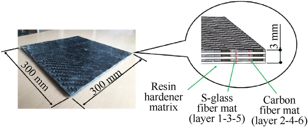
Fig.1.S-glass/carbon fiber reinforced epoxy laminates.
To evaluate the axial stress withstanding ability of the prepared laminate,the samples were cut according to ASTM D3039(120 × 20 × 3 mm3) standards using a cutting die and benchtop press.Tensile testing was carried out using a universal testing machine(Instron 4855,USA)equipped with a 100 kN capacity load cell.Energy absorbed by each laminate was tested using an Izod impact testing machine according to ASTM D256-04.To evaluate the transverse loading ability of the prepared laminates,three point bending test was carried out with samples (100 × 20 × 5 mm3)according to ASTM D-790.Unless otherwise stated,all samples were tested three times and the average results were reported.Scanning electron microscopy (SEM) was performed using JSM-7600F (JEOL Inc.,Japan) with an accelerating voltage of 2-5 kV.Surfaces of the un-fractured samples and fractured samples were first coated with~4 nm of Pt using Hitachi S-3000 N machine and examined to understand the microstructure.
3.Results and discussion
3.1.Mechanical properties
Table 1 shows the mechanical properties of fabricated carbon fibers/S-glass fibers reinforced epoxy composite.From Table 1,it can be seen that the tensile modulus and flexural modulus of the composite were 26650 MPa and 9167 MPa respectively.On the other hand,the tensile and flexural strength of the composites were 335 MPa and 146 MPa respectively.The nature of loading in uniaxial tensile test is different from three point bending test.For instance,the stress and strain during tensile testing will be homogeneous in the elastic region during loading assuming no localization effect.On the other hand,in bending test while certain cross section of the sample will be in tension mode,other parts of the sample will be subjected to compression;besides which it also takes the shear component of the stress.The reasons aforementioned could lead to lower bending properties in comparison to tensile properties.Moreover,brittle materials are highly sensitive to the defect population;thus prone to have lesser tensile properties than bending properties.In another interesting study,it was reported that cellulose fabric Elium®-thermoplastic composite did not show fracture even after 7%bending strain instead showed only tiny cracks (without signs of delamination or breakage) on the tensile and compressive sides of the sample [29].
It should be noted that the reported tensile strength(335 MPa)can give rise to remarkable specific strength.While the tensile modulus of the carbon fibers/S-glass reinforced epoxy composites in the present study is higher than aluminium commonly used for submarine hull(experimentally obtained value:193 MPa[30]),the specific yield strength of the composite in the current study can exceed that of steel or Al 7075,one of the strongest aluminium alloy grade commonly used for submarine hull application[31-33].Izod impact test showed the energy absorbed in Joules of the carbon fibers/S-glass fibers reinforced epoxy composite.The energy absorbed by the composite upon impact was 10.3 J.The excellent impact energy absorption of carbon fibers/S-glass fibers reinforced epoxy composites in the present study can be attributed to the excellent interfacial bonding (i.e.interlaminar adhesion and delamination resistance)of fibers with epoxy matrix which hinders the initial break,subsequent break pinning mechanism and the extension of crack within the composite when force is applied.Thisalso indicates the carbon fibers/S-glass fibers reinforced epoxy composite as a tough composite material suitable for submarine hull application subjected to hydrostatic pressure.
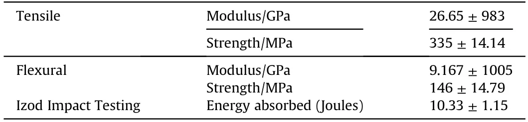
Table 1 Mechanical properties of carbon fibers/S-glass reinforced epoxy composites.
In addition,plotting the elastic modulus-density and strengthdensity data of carbon fibers/S-glass fibers reinforced epoxy composite on the Ashby chart as shown in Fig.2,the data point of the composite extends out of the polymer region and falls closer to properties exhibited by metallic materials.This indicates that the composite in the present study is able to achieve a combination of strength,stiffness and density that is comparable to many composites or metals at lower density (i.e.higher specific strength and stiffness).Based on the experimental findings,mechanical properties such as yield strength=335 N/mm2,modulus in transverse direction=9167 N/mm2and mass density ρ=1769 kg/m3were used in FEA simulation.
3.2.Surface morphology of composites
Fig.3 shows the SEM analysis of unfractured and fractured samples of carbon fibers/S-glass fibers reinforced epoxy composite.Fig.3(a) shows the unfractured area of the composite where good interfacial bonding due to excellent adhesion between reinforced fibers and matrix were observed.The excellent interfacial bonding ensured the effective stress transfer from the epoxy matrix to the fibers,through which strength of the fibers can be utilized to its full potential in the composite[34,35].SEM images of carbon fibers/Sglass fibers reinforced composite subjected to tensile testing is shown in Fig.3(b)-Fig.3(h).It can be seen that split fragmentation exists on the carbon fibers/S-glass fibers,besides which failure mechanisms such as fiber breakage,pull outs,crack deflection and matrix cracking were observed when the composite samples were subjected to tensile testing at a speed of 15 mm/min.The long carbon and glass fibers were capable of carrying more load due to an increased transfer length and the enhances adhesion with the polymer matrix;thereby leading to the excellent mechanical properties of carbon fibers/S-glass fibers reinforced epoxy as reported in Table 1.For instance,if a crack propagates and meets the fibers,it is arrested and deflected in plane.Such crack deflection mechanism creates a complex path way to release stress which helps to increase toughness of polymer composites[36,37].To this end,characterization and mechanical tests of carbon fibers/S-glass fibers reinforced epoxy revealed that this material is better than many existing metallic materials.
3.3.Modeling of bow,stern and foil
The interest of numerical analysis is to investigate the suitable hull design for varying sea level from 0 to 7000 m.For bow analysis,two different shapes;hemispherical (labeled as B1-B9) and elliptical shapes (labeled as B10-B18) were used.The diameter and length of hemispherical bow models were 130 mm and 228 mm,respectively.The diameter and length of elliptical bow models were 130 mm and 228 mm,respectively.The thickness of both models were varied from 4 mm,8 mm,12 mm,16 mm,20 mm,24 mm,28 mm,32 mm and 36 mm.Hence,a total of 18 different models of bow was created.
For stern analysis,two different models;conical (labeled as S1-S9) and elliptical shapes (labeled as S10-S18) were used.The dimensions for conical stern shape were 130 mm in diameter,390 mm in length at an angle of 8.89°while the dimensions for elliptical shape were 130 mm in diameter and 390 mm in length.Eighteen different models of stern were used by varying thickness from 4 mm,8 mm,12 mm,16 mm,20 mm,24 mm,28 mm,32 mm and 36 mm.For hydrofoil analysis,hemispherical (labeled as F1-F4) and elliptical shapes (labeled as F5-F8) were used.The dimensions were 145 mm (horizontal length),65 mm (vertical length) at an angle of 16.48°.A total of 8 models were used in the analysis.The dimensions of all models are shown in Fig.4.

Fig.2.(a) Young's modulus-density data and (b) Strength-density data of carbon fibers/S-glass fibers reinforced epoxy composite plotted on an Ashby chart.
3.4.Material model and mesh metric evaluation
2D sketching tool and 3D tools such as extrusion,revolution and lofting/skin tools were exercised to render the models of bow,hydrofoil and stern separately and the corresponding IGS files were exported to ANSYS®for further analysis.The thickness of the bow models (B1-B9 and B10-B18) and stern models (S1-S9 and S10-S18) were varied as 4 mm,8 mm,12 mm,16 mm,20 mm,24 mm,28 mm,32 mm and 36 mm.The thickness of hydrofoil models(F1-F4 and F5-F8)were varied as 4 mm,8 mm,12 mm,and 16 mm.The foil thickness generally influences the stability of the submarine during the navigation.
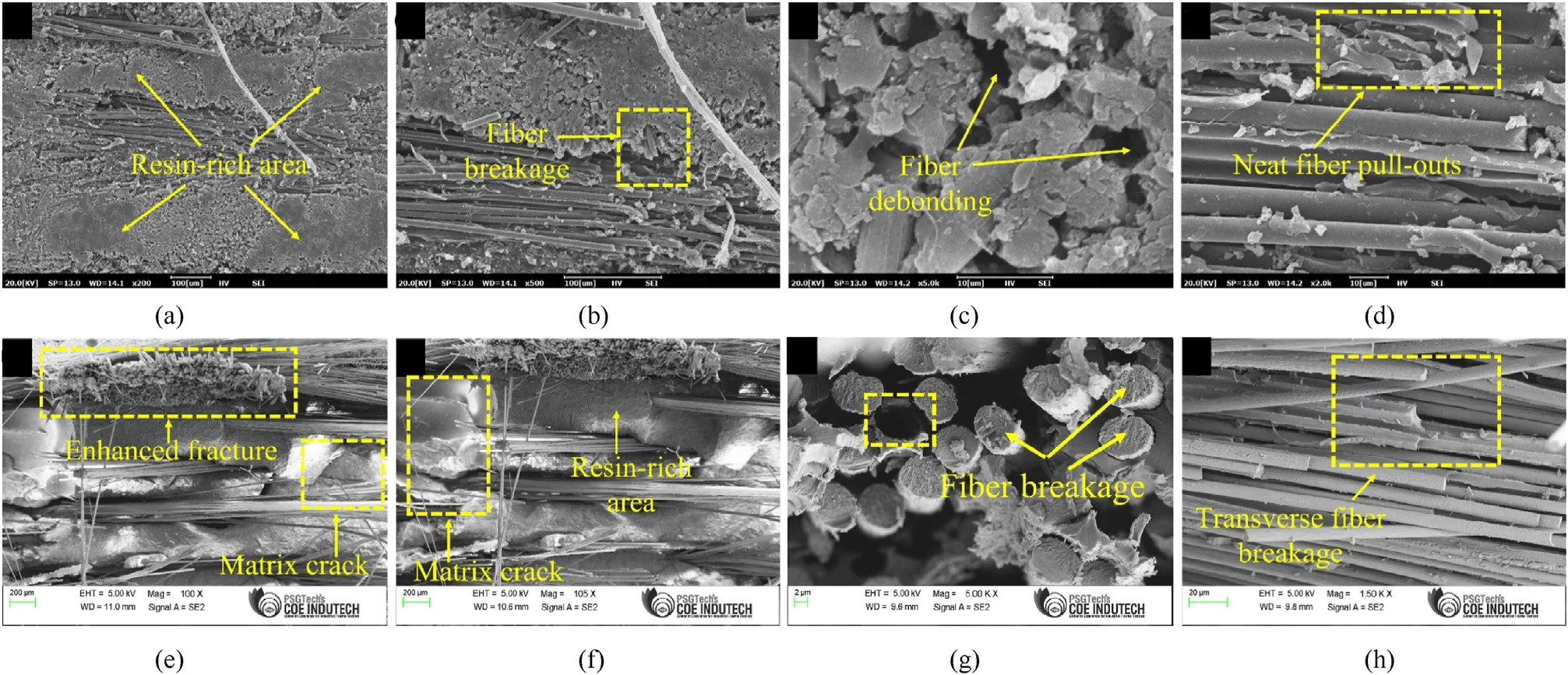
Fig.3.SEM images of S-Glass/carbon fibre composites for(a)un-fractured and(b)-(h)fractured surfaces illustrating the various toughening mechanisms that occurred between the fibers and matrix.
Transverse isotropic material model was considered in the present numerical analysis since the S-glass and carbon fibers were aligned in parallel.Transverse isotropic material is a special class of orthotropic material that has the same properties in one plane(e.g.the x-y plane) and different properties normal to the respective plane.It is defined by five independent elastic constants(E,v,Ez,vz,Gz),where E,v are elastic modulus and poison's ratio in x-y plane,and Ez,vz,Gzare elastic modulus,poison’s ratio and shear moduls normal to the respective plane.Homogenization was not considered since we considered transverse isotropic material model for the analysis.In general,homogenization method is applied to predict the effective physical properties of the multiphase composites such as carbon fibers,carbon nanotubes or graphenes reinforced polymer composite,which exhibits anisotropic composite behaviour.
The correctness of the solution generally depends on the size and type of the element.The fine mesh of the model offers more converged solution that matches with exact solution of the engineering problem.Hence,mesh convergence analysis was performed to obtain optimum mesh size for finite element analysis.A simple displacement test was performed to evaluate the mesh metric.The test involved a cantilever beam with Uniformly Distributed Load(UDL)of 100 N to the endplate and measuring the resultant displacement of the elements.The length of the beam was 175 mm and the thickness was 20 mm.Mesh grid was gradually increased and the deflection of the beam was observed and compared with the analytical solution.Finally,0.32-0.35 of skewness mesh metric value with ten noded solid tetrahedral elements was selected,as numerical simulation result matched with the analytical solution with 3 decimals of accuracy.
After the mesh evaluation,the same mesh properties were used to prepare all the 44 mesh models.Simulations on all these 44 models were conducted at the depth of 0 m,1.70 m,3.42 m,6.84 m,13.7 m,27.3 m,54.7 m,109 m,219 m,438 m,875 m,1750 m,3500 m and 7000 m.The hydrostatic pressure of the sea water Pfluidcomputed below was used [22] as load input

where,ρ is seawater density(kg/m3),g is the gravity(m/s2)and h is the depth of hull (m).For instance,the Pfluid=0 when depth of travel is 0 m,whereas Pfluid=70.4967 MPa,when depth of travel is 7000 m.The displacement of the hull and von Mises stresses at varying travel depth were noted.Von Mises stressis an equivalent stress acting on the body.
3.5.Numerical simulation results - effect of thickness in bow
Fig.5 shows the von Mises stress on bow for varying thickness and depth of travel.When the hull travels at a depth of 0 m(Mean Sea Level),the stress intensity is negligible.However,it increases as the depth of travel was increased from 0 m.The maximum stress was recorded at the condition when bow thickness=4 mm and depth of travel=7000 m.As the yield strength of the selected material (carbon fibers/S-glass fibers reinforced polymer composite)was 324.77 MPa,any bow thickness resulting stress higher than this value must be ignored.For travel depth of 7000 m,von Mises stress on elliptical bow of varying thickness (24 mm,28 mm,32 mm and 36 mm) was 20.22%,19.95%,6.31% and 4.83% respectively;lower than that of the hemisphere bow.For travel depth of 3500 m,the stress intensity on elliptical bow of varying thickness(12,mm 16 mm,20 mm,24 mm,28 mm,32 mm,and 36 mm)was 13.7%,21.04%,24.24%,20.21%,19,95%,6.30%and 4.84%respectively;lesser than hemispherical bow.For travel depth of 1750 m,the stress intensity on elliptical bow (8 mm,12 mm,16 mm,20 mm,24 mm,28 mm,32 mm,and 36 mm)was 2.66%,13.7%,21%,24.24%,20.21%,19.95%,6.3%and 4.83%lesser than hemispherical bow.The stress on elliptical bow (4 mm,8 mm,12 mm,16 mm,20 mm,24 mm,28 mm,32 mm,and 36 mm)for travel depth of 875 m was 5.29%,2.66%,13.69%,21%,24.24%,20.20%,19.94%,6.29% and 4.29%lesser than the hemispherical bow.Upon analyzing the results,the following conclusions were drawn:
Table 2 shows the results obtained in the current study in comparison to another study by Waqas et al.[22]where numerical simulations were performed on hemispherical bow having 36 mm thickness and reported their Von-Mises stress values.They used different materials to investigate the suitable material for submarine applications.Considering the same thickness of 36 mm,the stress intensity of the current model is 37.39%lesser than Bamboo/Carbon,64.7% lesser than Bamboo/Glass,26% lesser than Paulownia/Glass,4.2% lesser than Balsa/Glass,62.43% lesser than Mulberry/Carbon,69.77%lesser than Mulberry/Glass,62.11%lesser than Eng-Mul/Carbon and 69.5% lesser than Eng-Mul/Glass lesser.Fathallah and Helal [23] reported that elliptical bow at a depth of 1772.5 m resulted 756 MPa,whereas the current study recorded only 80.9 MPa in elliptical bow at the same depth.
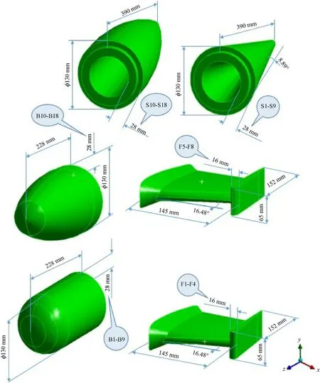
Fig.4.Dimensions and shapes of all different models used in FEA;B1-B9 and B10-B18 represent bow models,S1-S9 and S10-S18 represent stern models,F1-F4 and F5-F8 represent hydrofoil models.
Although,both hemispherical and elliptical bow of S-Glass/Carbon reinforced polymer composite appeared better in comparison to all materials used by Waqas et al.elliptical bow of 24 mm is recommended to be used in the submarine design since the induced stress is within the allowable stress of the material.Nevertheless,S-Glass/Carbon reinforced polymer composite used in the current research is a better material for submarine applications in terms of stress intensity.
3.6.Effect of thickness in stern
Fig.6 shows the numerical simulation results of conical and hemispherical stern with varying thickness of 4 mm,8 mm,12 mm,16 mm,20 mm,24 mm,28 mm,32 mm and 36 mm.For travel depth of 7000 m,the Von-Mises stresses on conical stern of varying thickness (16 mm,20 mm,24 mm,28 mm,32 mm and 36 mm)were 16.24%,12.27%,9.54%,7.7%.6.09% and 4.83% respectively lesser than that of elliptical stern.At travel depth of 3500 m,the stress intensities on conical stern of varying thickness (8 mm,12 mm,16 mm,20 mm,24 mm,28 mm,32 mm,and 36 mm)were 27.35%,19.12%,16.54%,12.74%,9.53%,7.76%,6.30% and 3.84%respectively lesser than elliptical stern.At travel depth of 1750 m,the stress intensities on stern(4 mm,8 mm,12 mm,16 mm,20 mm,24 mm,28 mm,32 mm,and 36 mm) were 21.78%,27.35%,19.21%,16.54%,21.74%,9.53%,7.6%,5.3%and 3.83%respectively lesser than elliptical stern.The following points were concluded upon analyzing the results.
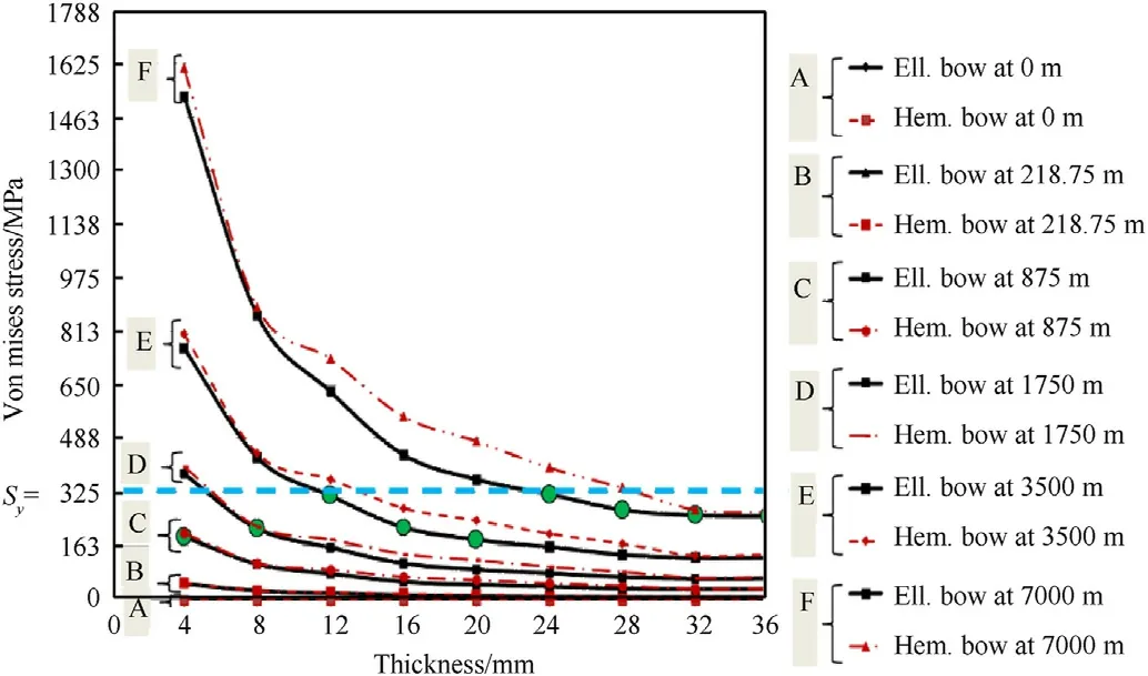
Fig.5.The effect of thickness on Von-mises stress in bow.
Besides,the current numerical simulation results reveal that the stress intensity is decreased with the increase in thickness.This is obvious that stress is a function of geometrical properties.The similar trend of the results was observed by Skopinsky [41,42],where experimental and numerical simulations were conducted on 4 mm conical stern part.The study on 4 mm conical stern of aluminum alloy conducted by Ref.[14] also reported that stress decreases with increase in thickness.In another research conducted by Umashankar and Santhosh [13],von Mises stress in conical stern of 1.6 mm resulted 144.72 MPa,while the current research reports von Mises of conical stern model with 16 mm to be 144.72 MPa at a diving depth of 3836 m.This is regarded as S-Glass-Carbon Reinforced Polymer Composites used in the current research is superior than other published research.
3.7.Effect of thickness in foil
Fig.7 shows the numerical simulation results of elliptical and hemispherical foil at varying thickness of 4 mm,8 mm,12 mm,and 16 mm.The trend of the results from elliptical foil and hemispherical foil is completely different from each other.Besides,the elliptical shape outperformed the hemispherical shape.The stress intensity of 4 mm thick foil at 7000 m was 100 MPa,which is well below the allowable stress of the material.The study done by Font et al.[38] on rectangular hydrofoil of Plastic FullCure material reported von Mises of 55 MPa at a depth 10 m,while the current model was able to record 55 MPa at a depth of 3900 m.In another study,Jebelli et al.[39] reported that foil of Teflon produced von Mises of 6.228 MPa at a depth of 8 m.In the present study,foil of 4 mm recorded von Mises stress of 6.228 MPa was achieved only at 442 m.These observations conclude that the S-Glass-Carbon Reinforced polymer composite outperforms all other materials used in published literature.
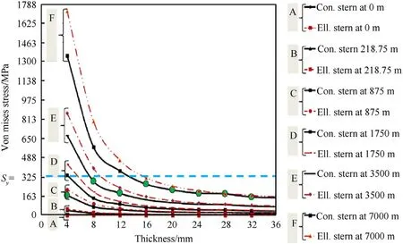
Fig.6.The effect of thickness on Von-mises stress in stern.
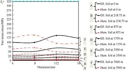
Fig.7.The effect of thickness on Von-Mises stress in hydrofoil.
3.8.Complete assembly of submarine hull
It is concluded from the above results that 24 mm elliptical bow,16 mm conical stern and 4 mm elliptical hydrofoil are the optimum design parameters to build the submarine hull which can travel at the depth of 7000 m.Fig.8 shows the complete assembly of submarine hull.The current design parameters differ from Binbin and Weicheng [40],who used titanium material with thickness of 76-78 mm.It must be noted that lesser thickness allows lesser inertial load which in turn assists in dynamics of the submarine hull.

Table 2 Comparison of von Mises stress on 36 mm bow model at travel depth of 500 m in comparison to other study.
4.Nonlinear crash analysis
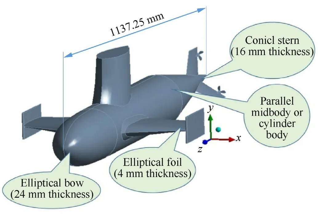
Fig.8.The assembly of the submarine hull.
Considering the mass of the hull as lumped mass,the dynamics of the system [41] is expressed as

where mü is the inertia force fI,is the viscous damping force fD,fs(u)is the nonlinear elasticity of the body,p(t)is the harmonic load acting on the body.

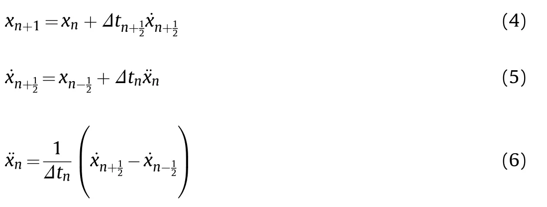
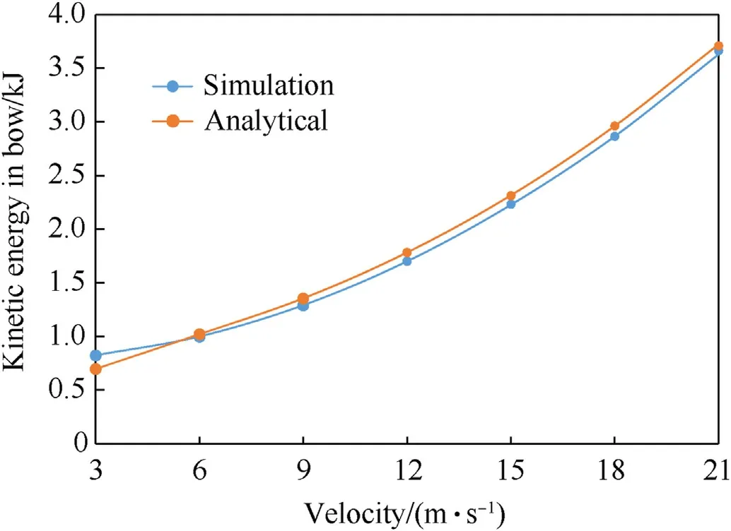
Fig.9.Validation of numerical simulation results.
The accidental and spontaneous load of the collision impact has a very short time,which includes actual collision time and explicit time integration type.The phenomenon of collision in explicit is implemented based on the d’Alembert’s principle about dynamic equilibrium as shown in Eq.(2)and Eq.(3).The motion of velocity,acceleration and displacement in mathematical expression is given in Eq.(4)-Eq.(6)which have been transfigured by ANSYS LS-DYNA explicit code for crashworthiness calculations.
The nonlinear explicit dynamic analysis on impact was conducted using ANSYS LSDYNA explicit code.The current nonlinear collision analyses involve bow-hull interaction,stern-hull interaction and foil-hull interaction.The striking submarine was modelled as a rigid body with titanium alloy.The struck submarine (current model) was modelled with S-glass and Carbon fiber reinforced polymer composite.The kinetic energy,internal energy,critical stress and shear stress were estimated for velocities ranging from 3 to 21 m/s.
The kinetic energy [42] can be given as follows.
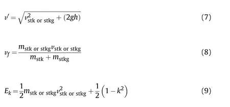
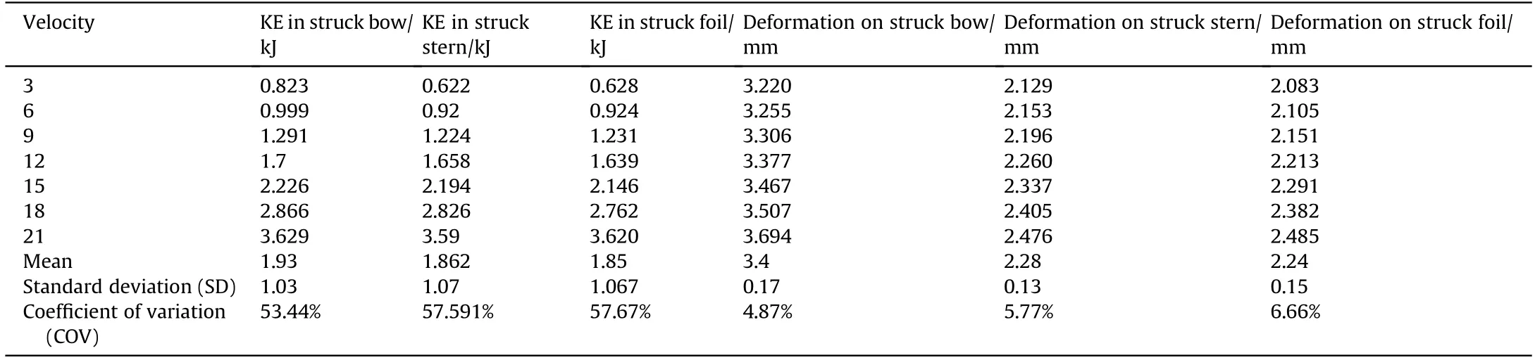
Table 3 Kinetic energy and deformation on struck submarine at 1750 m depth.

Fig.10.Impact acceleration at (a) bow,(b) stern,(c) foil.
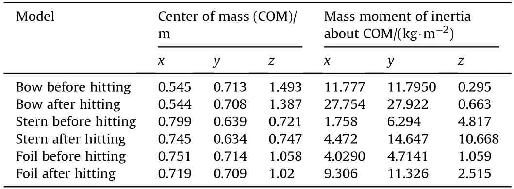
Table 4 Center of mass and inertia about center of mass.
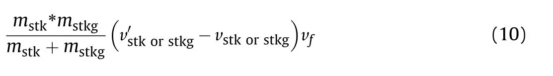
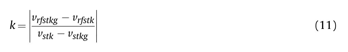
where,vstkis the velocity of struck submarine,vstkgis the velocity of striking submarine,v'is the velocity of striking or struck submarine with respect to varied depth and gravity of acceleration and vfis during both mass crashing.Ekis kinetic energy or energy dissipated while g represents gravitational acceleration and h represents the depth at which submarine travels at the time of crash.The mass of the struck submarine(mstk)and mass of striking submarine(mstkg)were taken as 13.135 kg and 34.5 kg (excluding the mass of other entities like passengers,goods,accessories inside the submarine).The k is the coefficient of restitution in the range of 0-1.It is the ratio of relative separation velocity to the relative approach velocity.

Fig.11.Safety factor of struck submarine hull: (a) bow,(b) stern,(c) foil.
where,vrfstkgis reference final velocity of struck submarine after impact relative to velocity of 2 m/s,while vrfstkis reference final velocity of striking submarine after impact relative to velocity of 2 m/s.During the deformation phase,the relative approach velocity decreases from its initial value to zero due to the action of the deformation impulse.The maximum dynamic crash occurs at the time when relative approach velocity is zero.Solid TET4 with skewness of 0.42-0.45 was used to mesh both striking and struck submarines.This four noded element was chosen rather than 10 noded or 16 noded element,because of easy computation.The fine element size was used to ensure the accuracy of the simulation.46986 elements were used to mesh the bow model,46695 elements were used to mesh the stern model and 49890 elements were used to mesh foil model.The velocity of the submarine at crash were v1=3,v2=6,v3=9,v4=12,v5=15,v6=18 and v7=21 m/s.The crash analysis were done at travel depth of 1750 m,3500 m and 7000 m to study crashworthiness.Kinetic energy,internal energy and stress in struck and striking submarines were observed in each case.
4.1.Discussion on the effect of crash
When the crash occurs straight against the target(bow,stern or foil of struck submarine),it is expected to have high collision leading to tear at the point of crash.The kinetic energy(KE)exerted in the submarine is one of the measures of impact.The acceleration of any part at crash depends on KE induced during the crash.The deformation of the body is the measure of safety of passengers or persons inside the submarine.
Table 3 shows the KE and deformation in struck submarine.The kinetic energy in bow,stern and foil of striking submarine(titanium material) and struck submarine (S-Glass/Carbon reinforced polymer composite) is increased with respect to time.Besides,KE of striking submarine is higher than that of the struck submarine in most of the cases.As coefficient of variation in KE is above 50,it is understood that the velocity of the submarine at crash has more effect on kinetic energy.
At travel depth of 7000 m,when velocity ranging from 3 to 21 m/s,KE at struck bow was higher than striking bow.At a travel depth of 3500 m,when velocity was 15-21 m/s,KE of struck bow was lower than striking bow.At a travel depth of 1750 m,when velocity ranging from 9 to 21 m/s,KE in struck bow was lower than striking bow.The KE in struck submarine tends to sunken over the time and looks better than striking submarine.It is regarded to be the reason for lower KE in struck submarine.From these results,it can be concluded that KE in the struck bow is influenced by both the velocity and the travel depth.Hence 1750 m and 3500 m is recommended to travel,beyond which the effect of crash will be higher for S-Glass/Carbon reinforced polymer composite material.
The kinetic energy at bow of struck submarine at crash was analytically computed using Eq.(7)-Eq.(11) for validating the simulation.Fig.9 compares the analytical results and simulation results.It is concluded from this validation that numerical simulation results well match with the analytical results with a small deviation.
Fig.10(a)-Fig.10(c) shows the acceleration on bow,stern and foil during the crash.The lowest acceleration peak and steady state acceleration was observed when the crash occurs at 1750 m of depth.The highest peak was observed when the crash occurs at a depth of 7000 m.Table 4 shows the center of mass(COM)and mass moment of inertia of the parts before and after crash.The center of mass was relocated after hitting.The safety factor for bow,stern and foil at 1750 m were found to be 5.9392,10.327 and 15 respectively as shown in Fig.11.The standard safety factor recommended for submarine design is 5 (five) [43,44] and hence the measured safety factors are within the standard safety factor recommended for submarine design.As computed safety factor is within the standard recommended value,the design is considered safe to the considered loads.
5.Conclusions
The present study investigated the suitability of S-Glass/Carbon fibers reinforced polymer composite for design of submarine hull that can travel up to 7000 m of sea depth.Experimental investigation revealed that the composite material exhibited combination of strength,stiffness and density that is comparable to many composites or metals at lower density (i.e.higher specific strength and stiffness).The excellent impact energy absorption (10.3 J) of carbon fibers/S-glass fibers reinforced epoxy composites in the present study was attributed to the excellent interfacial bonding of fibers with epoxy matrix.Extensive numerical simulations were done to determine the suitable shape,thickness of bow,stern and foil of the submarine and it was shown that elliptical bow of 24 mm in thickness,conical stern of 16 mm in thickness and elliptical hydrofoil of 4 mm in thickness were able to travel better at depth of 0-7000 m.The crash analysis was conducted at different velocity and different depth of travel and it was shown that the kinetic energy of struck submarine is lower than that of striking submarine.The safe depth of travel for crashworthiness was found to be 1750 m.The safety factor,kinetic energy,internal energy and deformation of parts were also discussed and it was concluded that S-Glass/Carbon fibers reinforced polymer composites are mechanically stable to withstand the hydrostatic and impact loads.
Declaration of competing interest
The authors declare that they have no known competing financial interests or personal relationships that could have appeared to influence the work reported in this paper.
杂志排行

Defence Technology的其它文章
- Damage response of conventionally reinforced two-way spanning concrete slab under eccentric impacting drop weight loading
- Analysis and design for the comprehensive ballistic and blast resistance of polyurea-coated steel plate
- Positive effects of PVP in MIC: Preparation and characterization of Al-Core heterojunction fibers
- Flight parameter calculation method of multi-projectiles using temporal and spatial information constraint
- Numerical simulation of drop weight impact sensitivity evaluation criteria for pressed PBXs
- Relationships between distribution characteristics of ceramic fragments and anti-penetration performance of ceramic composite bulletproof insert plates