Dynamic mechanical characteristics of NdFeB in electromagnetic brake
2023-01-18LeiLiGuolaiYangLiqunWang
Lei Li,Guo-lai Yang,Li-qun Wang
School of Mechanical Engineering,Nanjing University of Science and Technology,Nanjing,210094,Jiangsu,China
Keywords:Electromagnetic brake Sintered NdFeB Damage constitutive Dynamic mechanical characteristics
ABSTRACT With the continuous development of artillery,the disadvantages of hydraulic recoil brakes gradually appear.At the same time,the appearance of high-performance NdFeB permanent magnet makes it possible to apply electromagnetic braking technology to recoil mechanism.In this paper,prototype tests of a certain artillery were carried out to verify the feasibility of the electromagnetic brake (EMB) and obtain the electromagnetic braking force.Due to the brittleness of NdFeB,in order to eliminate the worry about the safety of EMB,SHPB experiments of NdFeB were carried out.Then,based on the assumption of uniform crack distribution,the law of crack propagation and damage accumulation was described theoretically,and the damage constitutive model suitable for brittle materials was proposed by combining the Zhu-Wang-Tang (ZWT) equation.Finally,the numerical simulation model of the artillery prototype was established and through calculation,the dynamic mechanical characteristics of NdFeB in the prototype were analyzed.The calculation results show that the strength of NdFeB can meet the requirements of the use in the working process.From the perspective of damage factor,the damage value of the permanent magnet on the far right is larger,and the damage value of the inner ring gradually decreases to the outer ring.
1.Introduction
Impact loads exist widely in engineering practices,such as the landing of spacecraft[1],non-contact impact of submarines[2],and launch of weapon systems [3].Some of these impact loads are random,but more of them are the excitation in the launching process or landing process,which is a part of its normal operation.To ensure the performance of this kind of engineering equipment under impact loads,it is necessary to introduce a buffer device to weaken or eliminate the negative effects caused by impact.For example,in the firing process of an artillery,the body and carriage of the artillery will be irreversibly damaged if the resultant force in bore is not buffered.In the design of artillery,the recoil mechanism takes the role of buffering the impact loads.Hydraulic recoil brakes were often used in the past.Problems arise,however,when they are in the process of specific use.Due to the existence of hydraulic oil,the requirements of sealing and transportation are put forward.At the same time,the temperature rise of hydraulic oil will lead to the uncontrollable braking force.Therefore,a new type of recoil mechanism is urgently needed to avoid the above problems.
With the appearance of rare earth permanent magnets (PMs),the coercivity and remanence of PMs have been greatly improved.In particular,the appearance of neodymium iron boron(NdFeB)in 1983 [4] and the subsequent continuous development made the performance of rare earth PMs further improved.This also provides the basis for the emergence of electromagnetic brakes(EMBs).EMB[5-7] is a new type of brake device which takes the magnetic energy of PMs as the power source and Faraday's electromagnetic induction law as the working principle.Different from the traditional brake device,it does not rely on contact and friction to produce braking effect,which avoids the generation of additional stiffness and friction force.At the same time,it uses PMs instead of liquid as the energy source,so there is no liquid leakage.In general,the EMB has the characteristics of simple structure,convenient maintenance,and good durability.
Nevertheless,the emergence of new brake devices also brings about problems that previous brakes did not have.The mechanical safety of materials should be considered first.Many studies show that NdFeB has poor plastic deformation ability [8-11],and the mechanical characteristics of PMs in the impact process are worthy of attention,which also determines the safety of EMBs.However,due to the short time of NdFeB,most of the current research is focused on improving its magnetic field performance.Due to the lack of corresponding research,we can only look for similar materials as a reference.The mechanical characteristics of rock,ceramics and other similar materials make the research on them have a good guiding significance for us.The current research on these materials can be roughly divided into damage evolution research and basic constitutive research.Ravichandran et al.[12]established a damage failure model for ceramics.In this model,the behavior of uniaxial compression was studied and the rate sensitivity of material characteristics was considered.Finally,the uniaxial compression behavior of aluminum nitride ceramics at strain rates of 5 × 10⁻⁶-2 × 10³s-1was predicted by the model and satisfactory results were obtained.Kokouvi et al.[13]proposed a thermo mechanical coupling damage method for describing dynamic shear failure of brittle solids.The model was developed from the dynamic evolution of microcracks and the friction heating effect at the crack tip provided the heat source for the whole model equation.The proposed model reflected the strong coupling relationship of mechanical field,temperature field and damage field and revealed the specific effects of micro size and strain rate on the response of macro structure.Finally,the feasibility of the model was verified by the temperature simulation of PMMA specimen under impact.Gui et al.[14]established a viscous fracture model and applied it to the discrete element method to simulate the fracture process in rock dynamic test.Inelastic displacement was used to correlate tensile strength and stiffness,and micro-damage parameters were used to consider the degradation of normal stiffness and shear stiffness under tensile conditions.In the verification of the model,the process of crack initiation and propagation until fracture in three different loading scenarios was studied.And it was found that the simulation could reasonably predicted the crack development process in rock test.The research on the damage evolution process was also mentioned in Refs.[15-17].In addition,the basic constitutive of brittle materials with strain rate effect is also a research hotspot.Among many nonlinear models,Zhu-Wang-Tang (ZWT)model [18] is an alternative model to describe the nonlinear dynamic constitutive model of NdFeB.The model was originally proposed as a nonlinear viscoelastic model for epoxy resin,plexiglass,nylon and other polymer materials [19-21],which can describe the mechanical behavior of polymer materials under the strain rate range of 10-4-103s-1.The model consists of a nonlinear spring and two Maxwell elements.It has strong nonlinear fitting ability and is increasingly applied to other materials.When considering the complexity of rock mass structure,Fan et al.[22]conducted a comprehensive study on the dynamic mechanical behavior and constitutive relationship of shale with different bedding.The basic dynamic mechanical properties of shale,such as dynamic tensile strength and failure strain,were analyzed,and an improved constitutive equation was established based on ZWT model.Meanwhile,ZWT model was also used to analyze the dynamic mechanical properties of frozen soil[23].Combined with the experimental results of frozen soil under different temperatures and high strain rates,the effects of low frequency parameters in the model on the application of frozen soil were evaluated.And the longitudinal wave velocity was used as the damage variable to modify the model to predict the dynamic mechanical response of frozen soil.Li et al.[24,25] first considered using the model to describe the dynamic mechanical characteristics of NdFeB and the damage of materials was calculated by means of experiment,modeling and simulation in the previous research.
This paper takes EMB as the research object and 122 caliber howitzer as the application occasion.The dynamic mechanical properties of NdFeB in EMB under the resultant force in bore are emphatic considered.The following is divided into four parts and the structure of the article is shown in Fig.1.In section 2,the artillery prototype tests are carried out.Through the analysis of the movement process,the feasibility of EMB is verified,and the experimental basis is provided for the subsequent modeling analysis.In section 3,the SHPB experiments of NdFeB are carried out and a dynamic damage constitutive model for NdFeB is established based on the experimental results.Furthermore,the numerical simulation model of the artillery prototype is established and the dynamic mechanical behavior of NdFeB is analyzed according to the calculation results in section 4.Finally,the work is summarized in section 5.
2.Structure of EMB and its prototype test
2.1.Structure and working principle of the artillery prototype with an EMB
Fig.2 is the topological diagram and specific structure diagram of the artillery prototype.Compared with the traditional artillery,there is no obvious difference in the overall structure of the prototype.The main improvement is the replacement of the brake.The traditional throttle rod hydraulic brake is to use the piston in the recoil process to squeeze the liquid in the working chamber to form the mainstream and tributary,which further produces the hydraulic resistance.The new type of EMB provides electromagnetic braking force through the induced current generated when the moving parts move relative to the composite cylinder.As shown in Fig.2(b),moving parts includes the barrel,breech and breech block,the moving rod,magnetic shoes,and NdFeB.The loads No.1,No.2,No.3,No.4 and No.5 selected in this paper correspond to No.4,No.3,No.2,No.1 and No.0 charges of 122 howitzer respectively.And the maximum breech pressures are 52.3 MPa,86.8 MPa,136.1 MPa,208.1 MPa and 230.9 MPa respectively.Under the action of the resultant force in bore,breech and breech block move in the opposite direction of the projectile,thus driving the moving rod,magnetic shoes,and NdFeB to move together.In the process of relative motion between the source magnetic field produced by NdFeB and the composite cylinder,inductive current is generated on the composite cylinder.The induced current creates a magnetic field that impedes relative motion and thus the moving parts are braked.To improve the utilization of magnetic field,NdFeB and magnetic shoes are arranged alternately.The composite cylinder is made of aluminum inner cylinder and steel outer cylinder.The aluminum inner cylinder has high conductivity and it can improve the induced current intensity.The steel outer cylinder has high permeability and the source magnetic field produced by NdFeB can be better recycled and utilized.In the process of tests,the corresponding test system is equipped,including acceleration sensor,force sensor and laser displacement sensor,to dynamically measure the corresponding data.At the same time,FASTCAM Mini UX50 high-speed video camera is used to capture the whole working process.
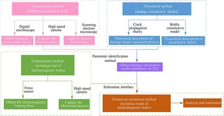
Fig.1.The structure of the article.
2.2.Prototype tests and results
Fig.3 is the motion pictures captured by the high-speed camera.By analyzing the motion,the process can be divided into three stages as follows:
1.The first stage is the accelerated motion stage,in which the whole device mainly bears the resultant force in bore.The main characteristic of this stage is that the breech and breech block bear intensive impact load in a short time.During the whole stage,the moving parts continue to accelerate under the resultant force in bore until the force disappears.At this moment,the moving parts have the maximum speed.
2.The second stage is the deceleration stage,in which the device is subjected to electromagnetic braking force and recuperator force opposite to the direction of motion.This stage follows the acceleration stage described above.Since the speed of the moving parts reaches the peak at this time,the electromagnetic braking force associated with it plays a major role in the deceleration of the moving parts.With the gradual deceleration of velocity,the electromagnetic braking force decreases gradually but the recoil displacement is still increasing.Therefore,the recuperator force gradually dominates behind.In general,the speed of the moving parts drops to 0 at the end of the second stage and the recoil displacement reaches the maximum value at this moment.
3.The third stage is the counter-recoil stage,in which the device mainly bears the recuperator force.Compared to the intense motion of the first two stages,the third stage is more gentle.Because the electromagnetic braking force is related to the velocity,it is relatively small at this stage and this article will not discuss in detail.
The curves of recoil displacement S,electromagnetic braking force Fe,recoil velocity v,and recoil acceleration a under different kinds of resultant force in bore are shown in Fig.4 and the corresponding peaks are given in Table 1.Both the figure and the table reflect the same phenomenon.First of all,the four observed values are improved with the increase of resultant force in bore.This is reasonable.The recoil process of artillery is the process of using recoil absorber force and recuperator force to slow down the powerful resultant force in bore.Therefore,greater electromagnetic braking force and recuperator force are needed to consume more energy.At the same time,larger recoil displacement and peak recoil velocity will result.In addition,it can be seen from the test results that the oscillation amplitude of the measured data increases with the increase of resultant force in bore.This is due to the aggravation of resultant force in bore,which makes the movement of the prototype more intense and makes the oscillation of test system intensified.
Fig.5 shows the performance comparison between EMB and hydraulic brake.As can be seen from the figure,the two maintain a high degree of consistency.There is no obvious difference between the two except the time of completing the braking process.This verifies the feasibility of electromagnetic technology in artillery,and also provides a new idea to solve the problems such as liquid leakage and maintenance difficulties of traditional hydraulic brake.
3.Dynamic mechanical experiments and damage constitutive model of NdFeB
3.1.Experimental method and results
Fig.6 shows the SHPB experimental system.As shown in the figure,the main part of the whole system is composed of a launch bar,an incident bar,a transmission bar and an absorber bar,all of which are 15.5 mm in diameter.The launch bar is 200 mm in length,which is used to absorb the kinetic energy of the air hammer and transfer the energy backwards.The speed of the launch bar will be monitored by the laser velocimeter.The length of the incident bar and the transmission bar is 1200 mm.Strain gauges are pasted at the same position on the incident bar and the transmission bar respectively,and the waveform data are obtained by combining the oscilloscope.The dynamic mechanical response of the sample is obtained by combining the three wave method.During the experiments,a light source and a high-speed camera are used to capture the dynamic change process of the sample under impact.
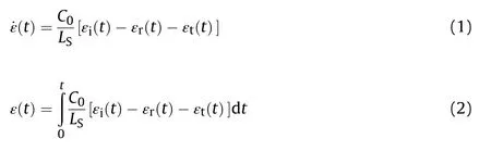
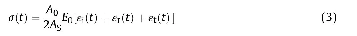
The strain rate ˙ε(t),strain ε(t) and stress σ(t) of the sample can be obtained by processing the incident wave εi(t),reflected wave εr(t) and transmitted wave εt(t) according to the formula below.Where,A0and ASare the end area of the steel bar and the sample,C0and E0are the elastic wave velocity and elastic modulus of the steel bar,and LSare the length of the sample.The diameter and length of the NdFeB sample adopted this time has a diameter of 14 mm and a length of 5 mm.
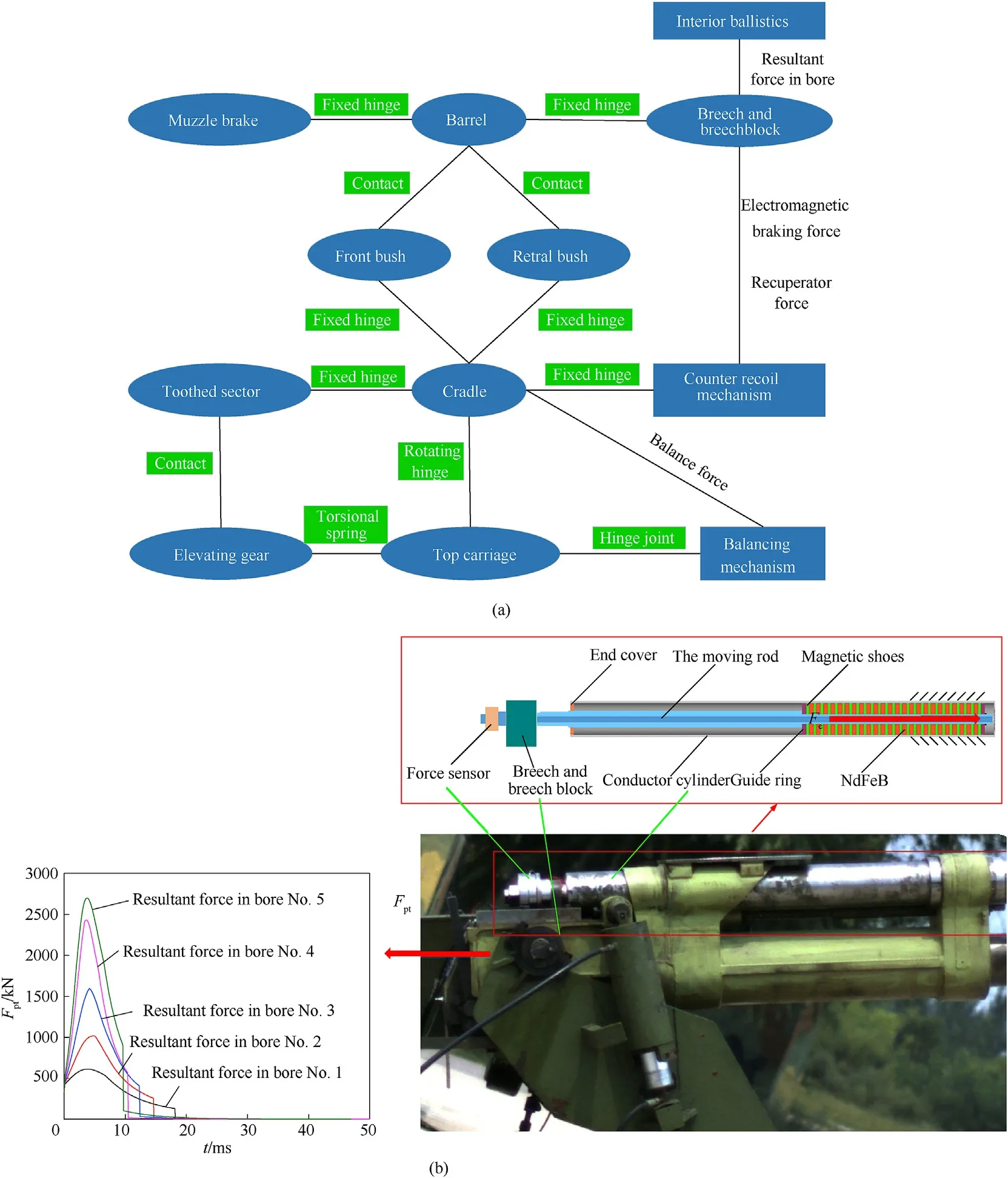
Fig.2.Topological diagram (a) and specific structure diagram (b) of the artillery prototype.
In SHPB experiment,the stress balance and uniform distribution at both ends of the sample is one of the preconditions that the system needs to meet,which also affects the results.A set of typical experimental results in Fig.6(a)are used to verify the stress balance and uniformity hypothesis of this experiment.As can be seen from Fig.6(b),εt=εi+εrcan be basically satisfied and the effectiveness of the experiments is ensured.Fig.7(c) shows the dynamic response results of sintered NdFeB under impact obtained through the above calculation.The results reflect that the mechanical properties of sintered NdFeB have obvious correlation with strain rate.With the increasing strain rate,the damage degree of the material increases gradually.At a relatively small strain rate (200 s-1),the material has no obvious external failure behavior.However,at the strain rate of 1500 s-1,the material has been destroyed into powder and cannot even be recycled.
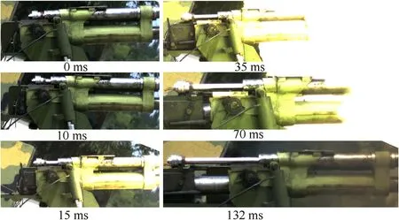
Fig.3.The movement process of the artillery prototype.
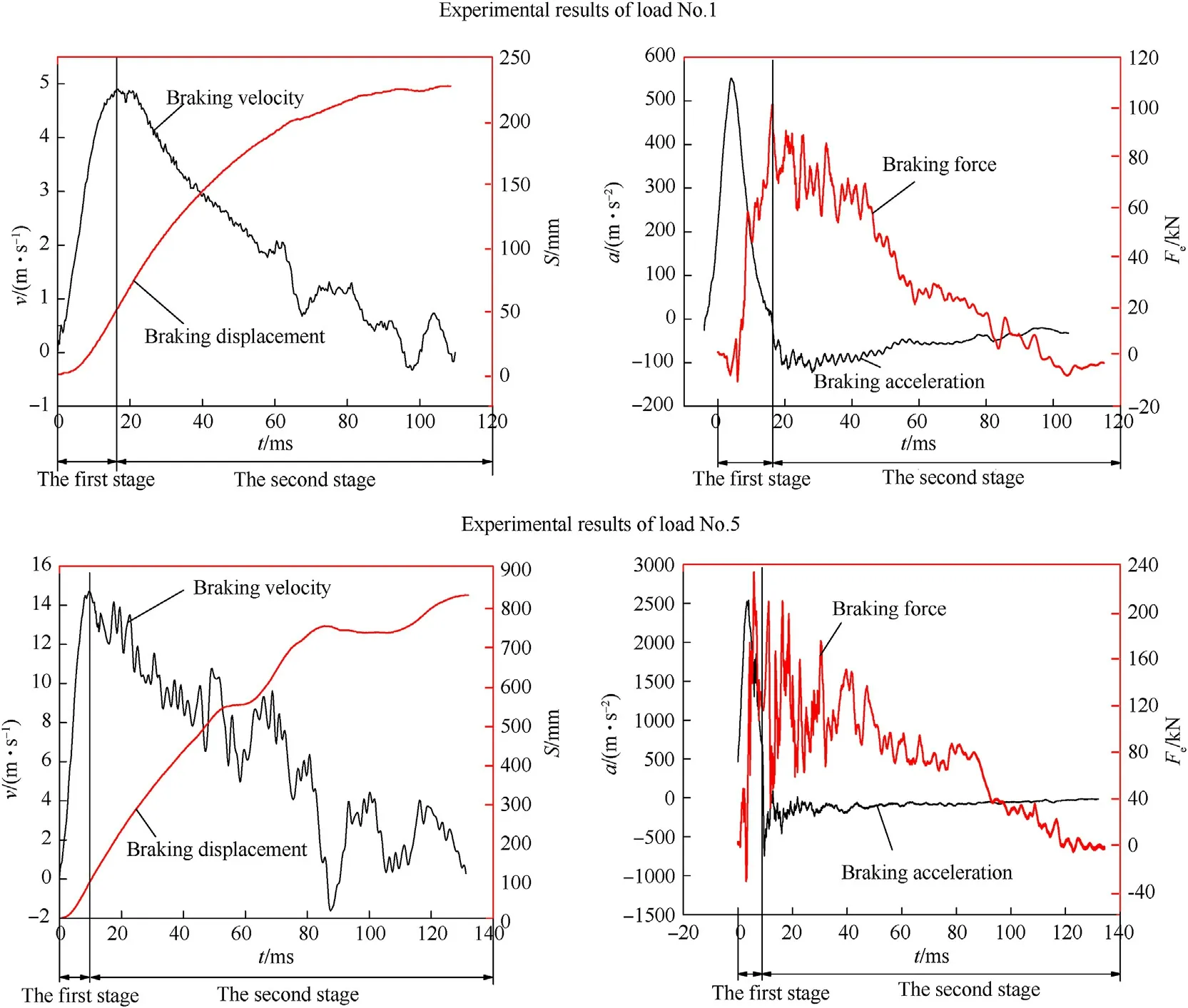
Fig.4.Experimental results of load No.1 and load No.5.
We recovered the fracture samples of sintered NdFeB after SHPB experiments,and photographed SEM images,as shown in Fig.8(a)and (b).At the same time,SEM images of PZT-5,which is also a functional material and also has obvious brittleness characteristics,is compared in Fig.8(c) and (d).It is found that the main crystal phase is polygonal Nd2Fe14B grain.The magnetic properties of NdFeB permanent magnet alloy are largely determined by the matrix phase Nd2Fe14B.The main crystal phase is produced under peritectic reaction at high temperature.The residual magnetism and maximum magnetic energy product of NdFeB mainly depend on the content of the main crystal phase in the alloy.There are almost no crystal defects and other inclusions in the main crystal phase,and the microstructure is very complete.At the same time,it can be seen that most neodymium-rich phases are distributed on the grain boundary in the form of thin layers,surrounding the matrix phase Nd2Fe14B grains,and a small amount of neodymiumrich phases are distributed in granular form.Neodymium-rich phase has a low melting point of about 650-700°Celsius.In the sintering process at a higher temperature,neodymium-rich phase can basically melt into liquid neodymium-rich phase,thus greatly improving the sintering density of the magnet.Although neodymium-rich phase belongs to non-magnetic phase,it can affect the coercivity and sintering density of permanent magnet alloy to a certain extent.Through the comparison with the microstructure of PZT-5,it is found that PZT-5 has a large number of cavities.It can be seen from Refs.[26,27] that 30-50 MPa is the fracture limit of PZT-5 under impact.From the SHPB experimental results of NdFeB,it has stronger impact compression resistance than PZT-5.In fact,this is closely related to the filling of neodymium-rich relative to the main phase.The existence of neodymium-rich phase allows voids in the structure to be filled so that the impact can be dispersed and transmitted.Finally,from the fracture morphology of NdFeB,the fracture surface is smooth and flat,which is an obvious brittle fracture feature.
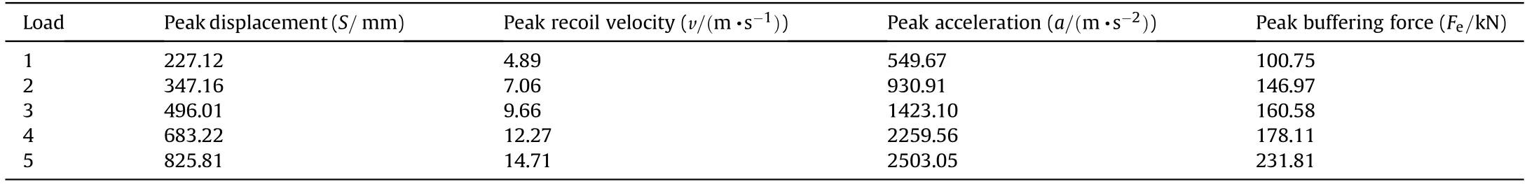
Table 1 Peak values under different loads.
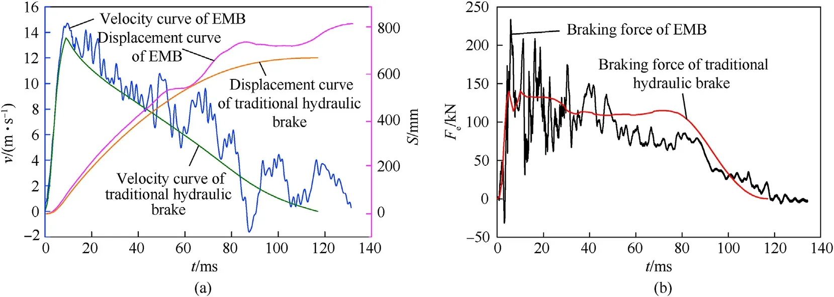
Fig.5.Performance comparison between EMB and traditional hydraulic brake under load No.5.
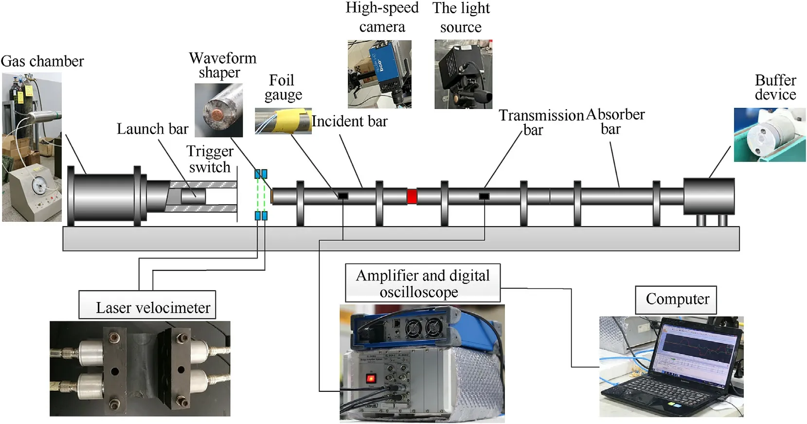
Fig.6.SHPB system.
3.2.Damage constitutive model
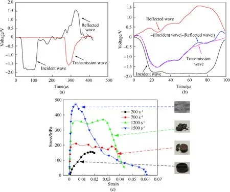
Fig.7.Experimental results: (a) a set of typical experimental results.(b) stress balance hypothesis.(c) dynamic response under different strain rates.
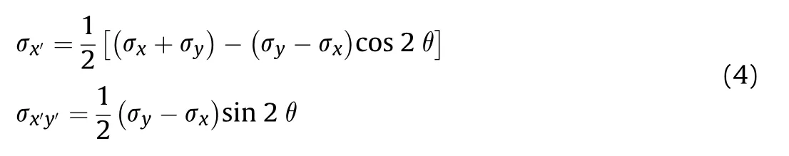
In this section,a theoretical model is established to describe the process of microscopic crack propagation until material failure.The whole derivation is carried out in the global coordinate system Oxy.The microstructure in Fig.8 is reasonably equivalent to Fig.9,and one of the microcracks is taken for expansion analysis.As shown in the figure,that the initial length of the defect is assumed as 2a and the extended length is c.
According to Ref.[12],the stress concentration factor of type I crack can be expressed as follow:
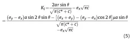
Where μ is the friction coefficient of crack slip,c* is the length of crack during initial propagation,and τ is comprehensive contact force of crack surface.
The strain of brittle material under uniaxial compression can be divided into elastic strain and crack propagation strain
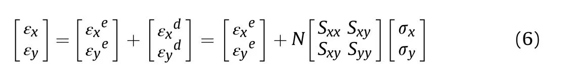
where ν is the Poisson's ratio,Sijis the flexibility tensor on crack,and N represents the number of cracks per unit area,defined as

and k and m are parameters related to processing technology and the microstructure of materials.
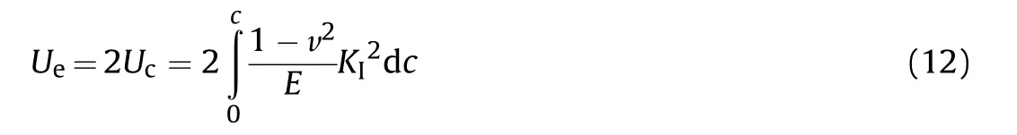
Energy conversion and conservation exist in the process of crack propagation.Specifically,the total energy of elastic deformation Ueand the energy of crack friction loss Wμshould be equal to the external work Wt.

Combining the flexibility tensor Sijand the area of crack surface S,we arrive at

The energy release rate G can be expressed as the derivative of the strain energy Ucto the initial value of the crack in the propagation direction b under fixed conditions.
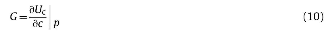
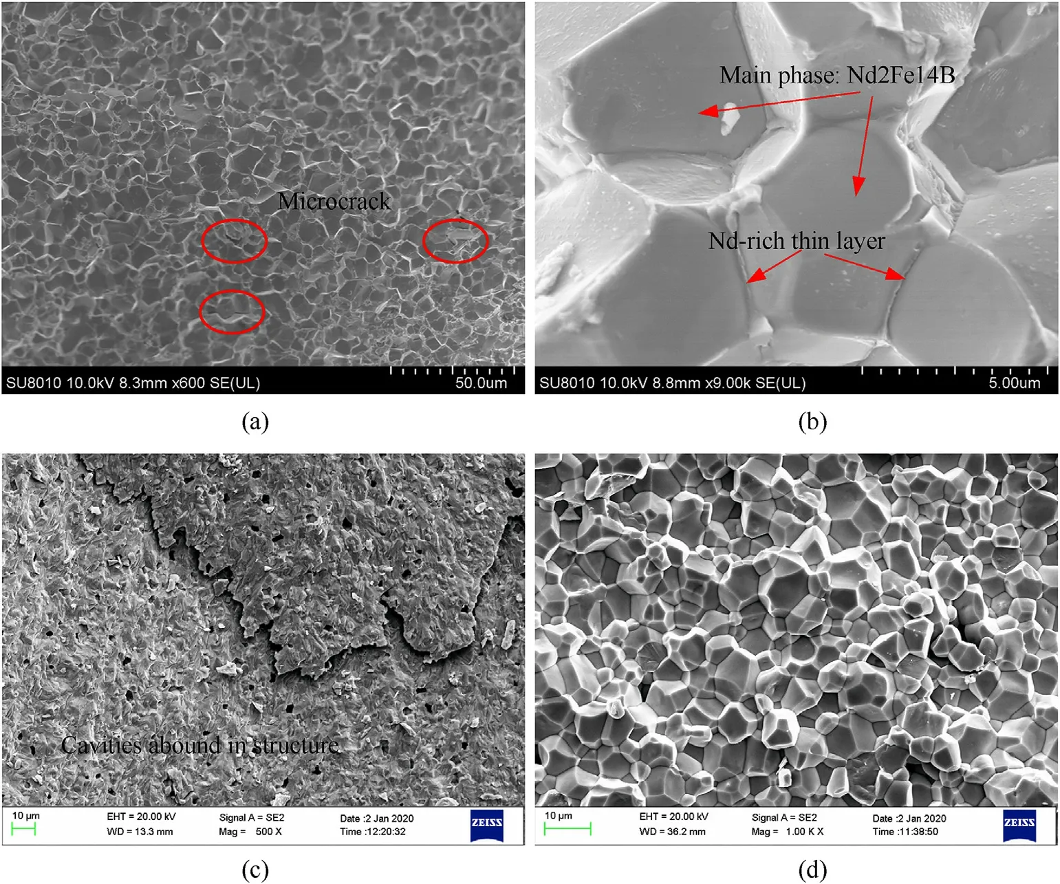
Fig.8.SEM of sintered NdFeB and PZT-5.
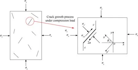
Fig.9.Crack growth diagram.
In addition,the crack growth rate G has the following relationship with the stress concentration factor KI.

It follows that
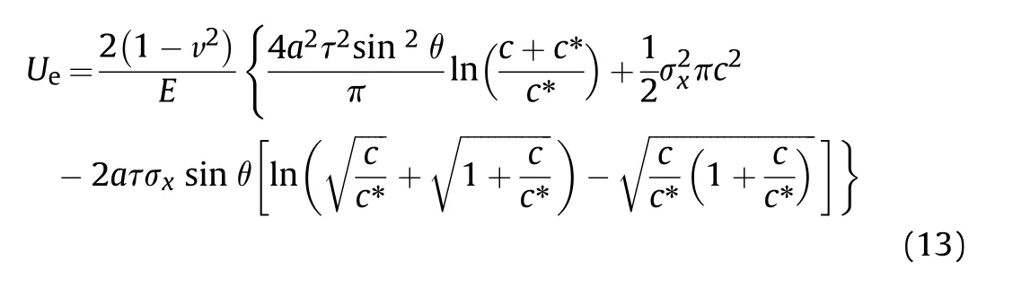
Substituting Eq.(5) into these results and integrating gives
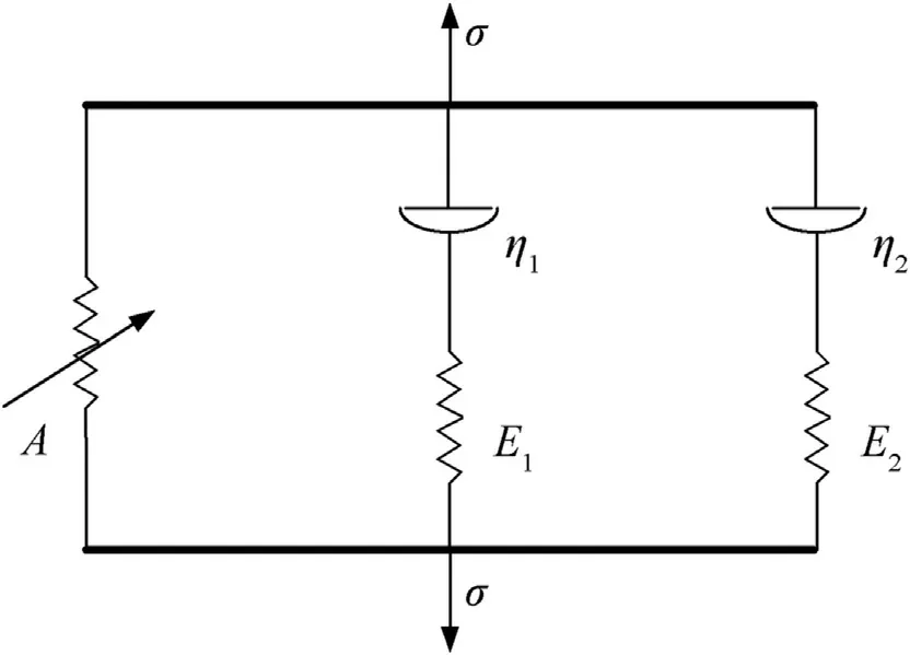
Fig.10.Physical model of ZWT constitutive.
Finally,the energy of crack friction loss Wμ is expressed by contact length ς.
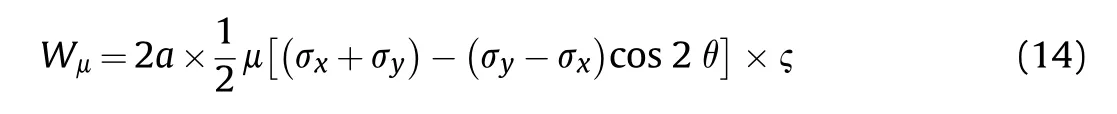
And the form of ς refers to the expression in Ref.[12].
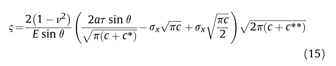
where c**is taken as 0.083a.Its existence ensures the stability of KIunder small deformation.
Substituting Eq.(15) into Eq.(14) and rearranging gives
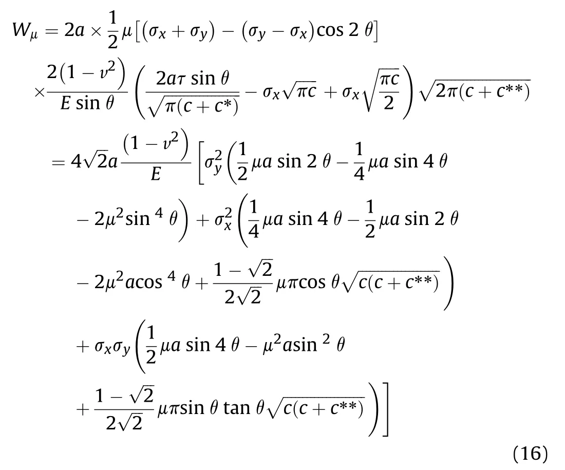
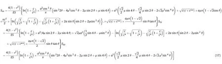
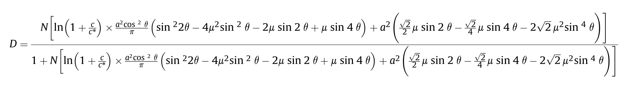
Substituting these expressions of Ue,Wμ,and Wtinto Eq (8)gives the following equation for Sxx,Sxy,and Syy:
In uniaxial compression,σx=0 and εy=σy/E+N×Syy×σy,and consequently,
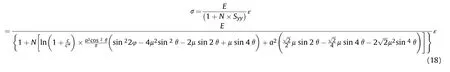
The constitutive equation of the damaged material in the onedimensional problem based on the strain equivalence hypothesis is:

where
The function f(v)with crack propagation velocity as variable can be used to describe the relationship between dynamic stress intensity factor KIDand quasi-static stress intensity factor KI,which is

Meanwhile,according to Griffith's crack growth criterion,there exists KID=KdIC.
In the choice of f(v),the following expression is usually adopted
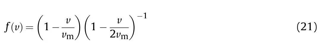
where vmis limit velocity of crack propagation.In numerical terms,it is usually taken as 0.4 times the Rayleigh wave speed.
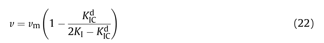
From the function given in Eq.(20) and Eq.(21),it is easily shown that the crack growth velocity v is given by
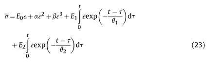
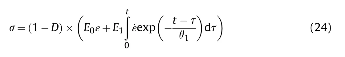
Through the above derivation,the crack propagation model of brittle materials has been established.Next,a complete dynamic damage constitutive model of brittle materials will be established by combining ZWT model.Fig.10 is the physical model of ZWT constitutive and its theoretical equation is shown in Eq.(23).In this model,elastic response constants E0,E1,E2,inelastic response parameters α,β,and relaxation time θ1,θ2are adopted to reflect the nonlinear constitutive relationship of materials.
In the process of simplifying the equation,only the high strain rate response phase is retained according to the needs of this article.Meanwhile,it can be seen from Fig.7 that in the initial stage of material deformation,the curve is almost coincident and linear.Therefore,the expression of damage modified ZWT model(DZWT)established in this paper is as follows:
3.3.Parameter identification
In the parameter identification of the above DZWT model,the parameter identification problem is transformed into an optimization problem.Firstly,the failure strain of the material is obtained by combining photos of experimental scenes.For example,Fig.11 shows the loading process of NdFeB at the strain rate of 1500 s-1.The high-speed photography pictures correspond to time and the pictures are rendered for observation.In the early stage,the microcracks inside the material continue to expand and nucleate,but it is not reflected in the macro picture.And the material reaches complete failure at 23 μs,which can be clearly seen in the picture.According to the time,the failure strain at this strain rate can be obtained as 0.016.The failure strain can be obtained similarly at strain rates of 700 s-1and 1200 s-1,with values of 0.011 and 0.014,respectively.The following identification process is carried out in 1st Opt.Meanwhile,we also use 1-D elastic brittle model to describe the dynamic response of NdFeB and compare with the model in this paper.The expression of 1-D elastic brittle model is shown in Eq.(25).
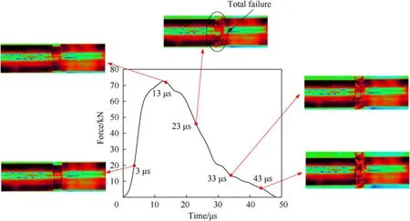
Fig.11.The curve of the load with time under the strain rate of 1500 s-1.

where p and q are parameters used to characterize the material failure process.
After identification,the model parameters of DZWT and 1-D elastic brittle model are shown in Table 2 and a comparison of curves is shown in Fig.12.It is obvious from Fig.12 that compared to 1-D elastic brittle model,DZWT model is obviously more accurate in fitting.In engineering,the fitting accuracy is usually expressed by the ratio of explained sum of squares(ESS)to total deviation sum of squares(TSS),R2.The maximum value of R2is 1,and the closer its value is to 1,the better fitting degree of the regression line to the observed value is;conversely,the smaller the value of R2is,the worse fitting degree of the regression line to the observed value is.It can be seen from Table 3 that under any strain rate,the fitting accuracy R2of DZWT model is much higher than that of 1-D brittle model.This also reflects the advantages of DZWT model in fitting NdFeB impact compression.In the following,the response of NdFeB under specific working conditions will be further analyzed by using this model combined with the dynamic model of electromagnetic brake.
4.Numerical simulation analysis and results
4.1.Simulation model
In this section,the numerical simulation model of artillery prototype is established and damage constitutive model mentioned above is introduced.The dynamic mechanical behavior of NdFeB is analyzed after calculation.Fig.13(a) is the mesh model of the artillery prototype and the calculation flow in ABAQUS is shown in Fig.13(b).The VUAMP amplitude subroutine is used to set the recuperator force to show its relationship with the displacement.At the same time,in order to combine the above damage constitutive model with the numerical model,the constitutive equation is first rewritten into the incremental form and the VUMAT materialsubroutine is used for calculation.The specific calculation process is as follows.Firstly,the basic setting of the artillery model is carried out,such as boundary conditions,common material model,etc.Then,in the initial stage of iteration,the resultant force in bore(In this section,the worst working conditions are considered and No.5 load is adopted)and the electromagnetic braking force are applied to the model.The displacement and material variables of the model are output by dynamic explicit calculation.The displacement results are passed into VUAMP for calculation to get the recuperator force,and the material variables are passed into VUMAT to output new material variables.The specific parameter iteration process of VUMAT is described in detail in Ref.[24].Finally,at the end of each iteration,whether the working process is completed or not is judged.If the working process is not finished,the iteration will continue,otherwise the whole calculation will be finished.
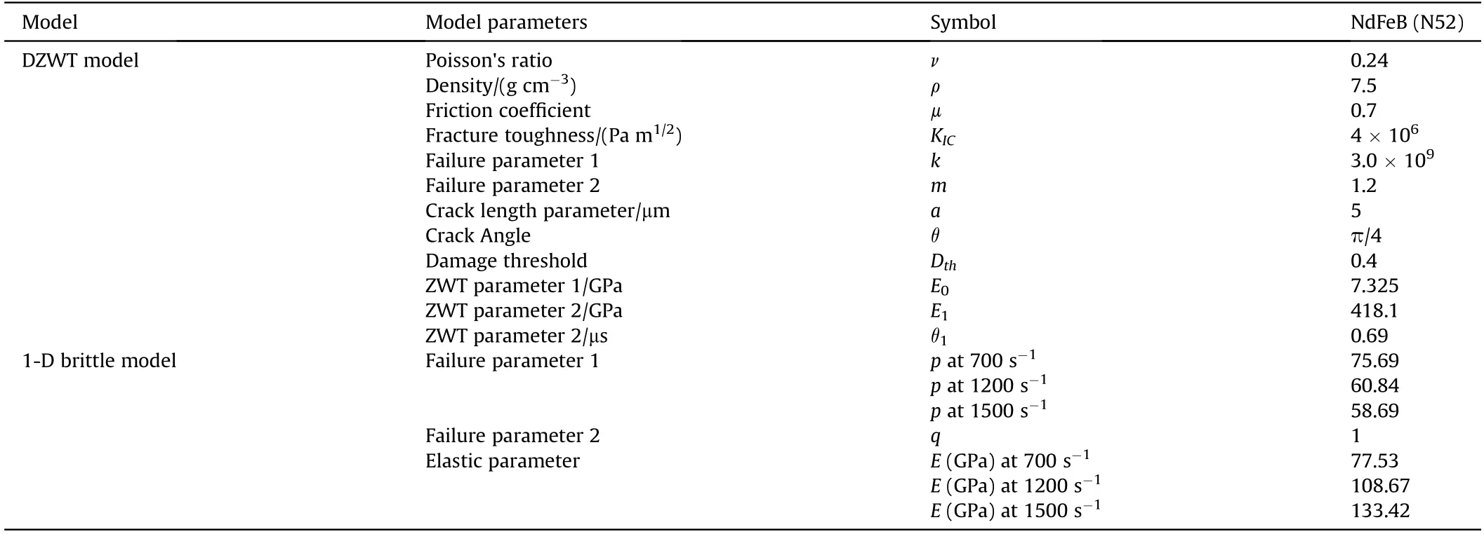
Table 2 Parameter identification results.
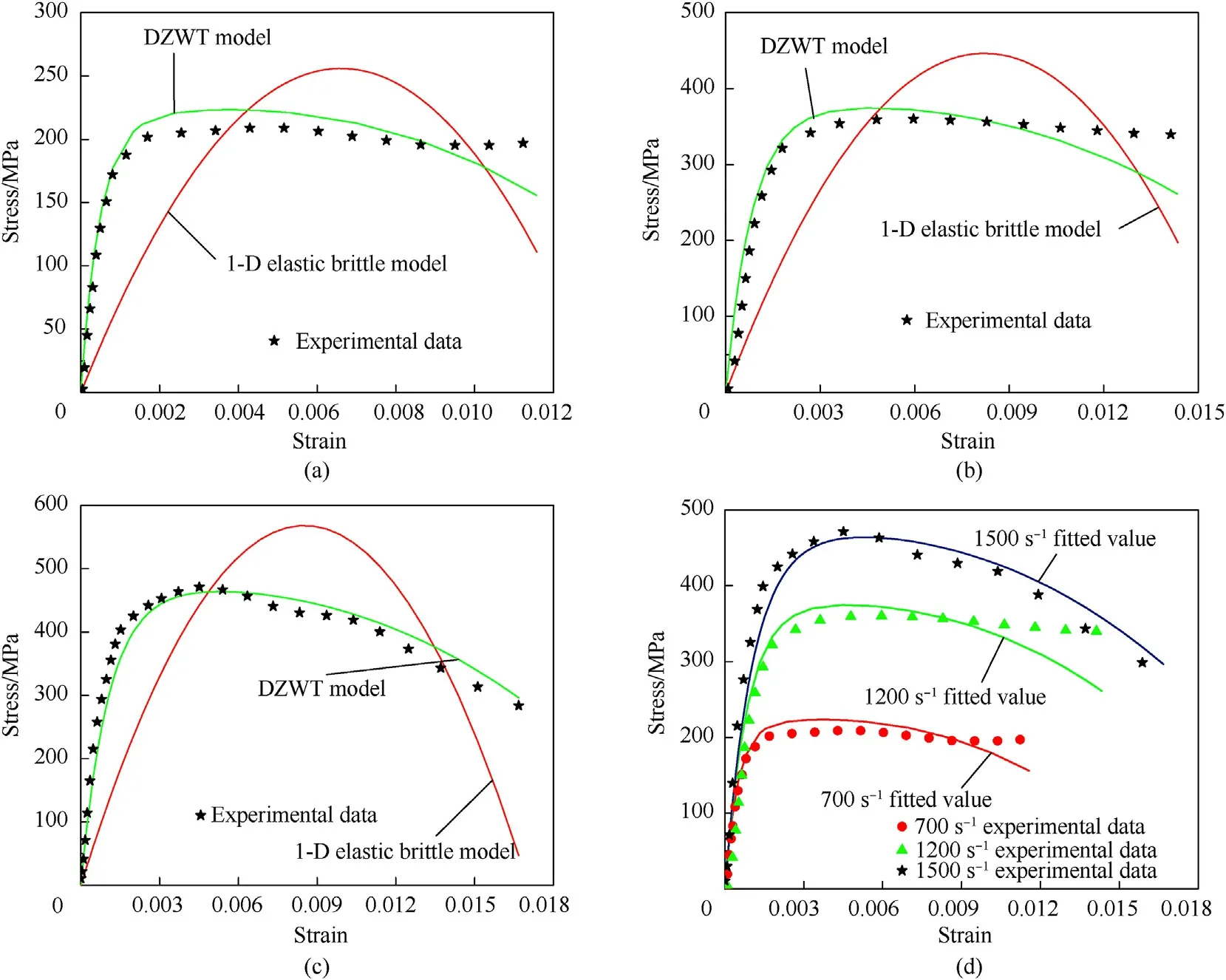
Fig.12.Comparison of fitting results under different strain rates: (a) 700 s-1.(b) 1200 s-1.(c) 1500s-1.and (d) DZWT fitting results under three strain rates.
Table 3 R2 comparison at different strain rates.
4.2.Simulation results
Fig.14 shows the simulation displacement results at different times,and compares the simulation results of recoil velocity and recoil displacement in Fig.15.Through comparison,it is found that the recoil process of simulation is basically consistent with the test data,and the simulation results can well reflect the working process of the artillery prototype.This proves from the side that the kinematic relationship of the mechanism and the applied load during simulation are consistent with the objective reality.
The simulation results in Fig.16 show that the stress distribution of the whole artillery prototype is the worst at the peak of the resultant force in bore.This situation is more obvious in the EMB.The global peak stress is 468.4 MPa at the connection between the right guide ring and the bolt.This is caused by the violent contact between the guide ring and the bolt caused by the high speed movement of the moving rod to the left when it is driven by the breech and breech block.For the permanent magnets part that we are most concerned about,the stress peak location is also in the right-most region where the collision is most serious.The stress peak is 67.8 MPa,which is far less than the material compression limit described above.Therefore,it can be seen from the numerical simulation results that EMB can bear the impact of the working process,and the mechanical safety of the whole artillery prototype and NdFeB can be guaranteed.
The damage distribution of NdFeB at 132 ms is shown in Fig.17.In axial direction,NdFeB which is still the right end with greater pressure and deformation has the maximum damage value.More severe collision means greater damage accumulation.When the right most NdFeB is taken out separately,the damage value of the inner ring decreases gradually along the radial direction to the outer ring.Taking three points A,B,and C on the ring,the damage values of three points are 0.00145,0.00011,and 0.00001 respectively.On the whole,the damage accumulation of single movement process is within the allowable range,and the buffer gasket can be used to reduce the damage accumulation in the area of greater damage.The calculation results provide theoretical support for the safety analysis of NdFeB,and provide guidance for the use and maintenance of EMB.
Fig.13.Mesh model of the artillery and its calculation process in ABAQUS.
Fig.14.Displacement results obtained by simulation.
Fig.15.Simulation results of recoil displacement (a) and recoil velocity (b).
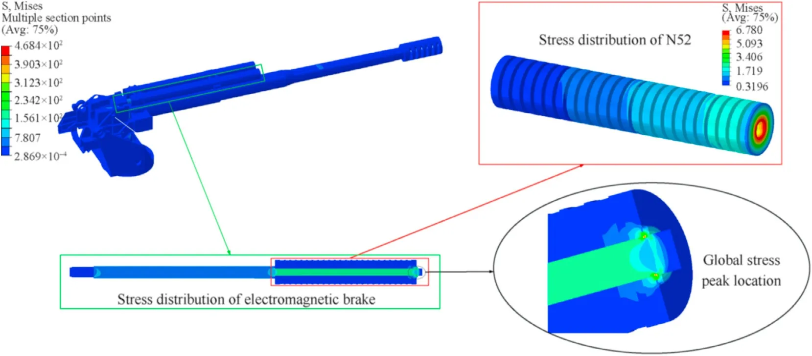
Fig.16.Stress distribution obtained by simulation.
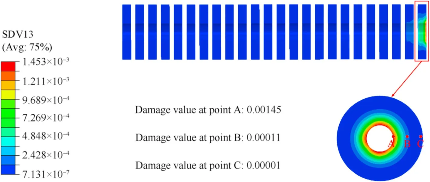
Fig.17.Damage distribution of NdFeB at 132 ms.
5.Conclusion
Aiming at the problems in the use of the hydraulic brake,this paper applies the electromagnetic brake technology to the artillery and the dynamic mechanical characteristics of NdFeB,an important functional component in EMB,is analyzed.The specific conclusions are as follows:
(1) The prototype tests of artillery with an EMB are carried out.According to the test data,it is found that the braking force produced by the new type of EMB can meet the requirements of recoil mechanism.The data of electromagnetic braking force under different loads are obtained and the force data are provided for the subsequent numerical calculation.
(2) The dynamic stress-strain curve of NdFeB is obtained through SHPB experiments.By combining the damage evolution law with the traditional ZWT constitutive model,a damage constitutive model is established to reflect the dynamic mechanical properties of brittle materials under impact.
(3) The numerical simulation model of artillery prototype is established.In the calculation process,VUAMP subroutine is used to apply the recuperator force,and VUMAT subroutine is used to calculate the material dynamic behavior.The calculation results show that NdFeB can meet the stress requirements in the process of working.In the distribution of damage value,the damage value of NdFeB on the far right is larger,and gradually decreases from the inner ring to the outer ring.This provides a reference for the use and main
tenance of EMB in the future.
Declaration of competing interest
The authors declare that they have no known competing financial interests or personal relationships that could have appeared to influence the work reported in this paper.
Acknowledgments
This research was financially supported by the“National Natural Science Foundation of China” [Grant No.52105106],the “China National Postdoctoral Program for Innovative Talents” [Grant No.BX2021126],the “Jiangsu Province Natural Science Foundation”[Grant No.BK20210342],the “Jiangsu Planned Projects for Postdoctoral Research Funds”[Grant No.2021K008A],and the“Nanjing Municipal Human Resources and Social Security Bureau”[Grant No.MCA21121].
杂志排行

Defence Technology的其它文章
- Experimental and numerical analysis on suitability of S-Glass-Carbon fiber reinforced polymer composites for submarine hull
- Damage response of conventionally reinforced two-way spanning concrete slab under eccentric impacting drop weight loading
- Analysis and design for the comprehensive ballistic and blast resistance of polyurea-coated steel plate
- Positive effects of PVP in MIC: Preparation and characterization of Al-Core heterojunction fibers
- Flight parameter calculation method of multi-projectiles using temporal and spatial information constraint
- Numerical simulation of drop weight impact sensitivity evaluation criteria for pressed PBXs