Research on a MEMS pyrotechnic with a double-layer barrier safety and arming device
2022-11-28KexinWngTengjingHuYulongZhoWeiRen
Ke-xin Wng ,Teng-jing Hu ,*,Yu-long Zho ,Wei Ren ,b
a State Key Laboratory for Manufacturing Systems Engineering,Xi"an Jiaotong University,Xi"an,710049,China
b Science and Technology on Applied Physical Chemistry Laboratory,Shaanxi Applied Physical Chemistry Research Institute,Xi"an,710061,China
Keywords:MEMS Pyrotechnics Safety and arming device Initiator Electro-thermal actuator
ABSTRACT As an essential component of ammunition,pyrotechnics can control ignition with high reliability.However,due to limits of fabrication technology,traditional pyrotechnics are bulky.To achieve both functionality and miniaturization,MEMS pyrotechnics integrate initiator,safety-and-arming(S&A)device and lead charge and keep all components within a small size.MEMS S&A devices,as the core component to ensure system safety,are difficult to achieve active and rapid response to control signals with high safety and reliability.In order to overcome the difficulty,we propose the design and characterization of a MEMS pyrotechnic with a double-layer barrier S&A device.The MEMS pyrotechnic is a high-integrated device with an overall size of 13.4×8.5×5.2 mm3.The initiator is a NiCr bridge foil covered with an Al/CuO energetic film,which can generate flame when ignited by an excitation voltage.To match the flame energy,lead styphnate is chosen in this study as the lead charge.The S&A device contains four semi-circular barriers,which are directly driven by V-shape electro-thermal actuators to gain active control of the pyrotechnics"ignition condition with rapid response.To improve the system"s reliability,the four barriers are axisymmetrically placed in two layers,two barriers for each layer,to constitute a double-layer structure with a thickness of 100 μm.The ignition test results show that the S&A device can prevent the initiator from detonating the lead charge in safety condition.In arming condition,the lead charge will be detonated.
1.Introduction
Pyrotechnics are the most sensitive components in ammunition to control ignition.Therefore,their safety and reliability affect the entire weapon system.Traditional pyrotechnics have strong antijamming ability and high reliability,but they are mostly bulky in size due to limits in the fabrication technology.Due to outstanding features such as minimized structure and easy integration,MEMS technology has gradually been more widely used in the pyrotechnics field.The MEMS pyrotechnics usually integrate initiator,safety-and-arming(S&A)device,and lead charge,and keep the components within a small size to form a micro explosive train[1,2].As the forehead of the train,the initiator can convert electrical energy into explosive energy,usually involving flames[3-6]and flyers[7,8],and the lead charge will be detonated after receiving the explosive energy[6-8].The S&A device is set in the middle to interrupt energy transfer or transmit energy through a movable barrier mechanism[1].Therefore,its performance is the key to ensuring the safety and reliability of the entire weapon system.
Classified by the driving principle of the movable barrier,the actuation methods of the MEMS S&A device mainly include inertial[9-11],electro-thermal[12-15],electro-magnetic[16,17],and pyrotechnic[18,19].The current difficulties of those MEMS S&A devices can be summarized:(a).Active driven method.MEMS S&A devices in early stage can only be actuated in specific inertial environment[9,10].With a smaller mass of barrier in micro-scale,the specific inertial force is too small to resist other interference,such as adhesion and friction.Therefore,MEMS S&A devices need an active driven method to adapt to the complex battlefields in modern warfare[1];(b).Rapid response.The judgment of ignited occasion is more ingenious in information warfare.The initiators usually have a high explosive speed in micro size[3-8].Therefore,MEMS S&A devices must rapid respond to control signals(safety to arming or arming to safety)to deal with emergence.However,confined by large displacement,the barrier is difficult to make fast movement in limited volume[13-15];(c).High safety.The initiator with high energy density is the most sensitive component in ammunition.To ensure safety of the train,all unreliable factors should be eliminated in MEMS S&A device.Silicon may break into pieces when block the detonation,and metal layer can be introduced to enhance the device structure strength.However,the metal-silicon composed structure fabricated by electroplating is costly and complicated for mass production[13].A simpler structure needs to be found to ensure reliability of the system.
To solve the difficulties mentioned above,we propose the design and characterization of a MEMS pyrotechnic with a double-layer barrier S&A device,which integrates initiator,S&A device and lead charge.The initiator is a NiCr bridge foil covered with an Al/CuO energetic film,and the lead charge is lead styphnate(LTNR).Ignited by an excitation voltage,the initiator will generate a flame to detonate the lead charge.The S&A device consists of two layers of SOI wafer,each containing two semi-circular barriers.The barriers are directly driven by V-shape electro-thermal actuators to gain active control of the pyrotechnics’ignition condition with rapid response.The four barriers are axisymmetrically placed in two layers to form a double-layer structure with a thickness of 100 μm to enhance the reliability of the system.The ignition test results show that the S&A device can prevent the initiator from detonating the lead charge in safety condition.In arming condition,the lead charge will be detonated.
2.Modeling
2.1.Overall structure of the MEMS pyrotechnic
As illustrated in Fig.1,the MEMS pyrotechnic is an assembly of different components,in which the initiator,S&A device and lead charge are the mainly functional parts that form an explosive train with an overall size of 13.4×8.5×5.2 mm3.To fix the relative position,PCB is introduced into the integrated system.The S&A device is placed on the upper surface of PCB with the pins,and the initiator is assembled into the chamber of PCB from backside.Circuits are also connected to the same plane via gold wires.As the intermediate device in the explosive train,the S&A device shall connect the initiator and lead charge in a compact manner.Thus,as illustrated in Fig.1(d),two chambers are designed at both ends of the S&A device.The bottom one is used as the ignition chamber connecting the initiator,and the top one accommodates the explosive chamber with lead charge in.Barriers are placed between the two chambers to isolate the lead charge from the initiator.All components are assembled in a linear and compact way.
The mission of the pyrotechnic is to trigger normal detonation and prevent accidental detonation,and the fundamental mechanism of the MEMS pyrotechnic is shown in Fig.2.When the pyrotechnic is in the safety condition,the barriers will cover the ignition chamber and allow no signal in.If the initiator is accidently ignited at this time,flames generated by the bridge foil will be kept within the ignition chamber and cannot reach and detonate the lead charge,as shown in Fig.2(a).Otherwise,driven by an arming signal,the ignition chamber will be open and the pyrotechnic will be switched to the arming mode.Flames will be allowed to pass through the S&A device and detonate the lead charge,as shown in Fig.2(b).In case of emergency,conditions of the MEMS pyrotechnic can be switched manually at any time.

Fig.1.Structure of the MEMS pyrotechnic:(a)Components;(b)Entity;(c)Cutaway view;(d)Detail view.

Fig.2.Fundamental mechanism of the MEMS pyrotechnic:(a)Safety condition;(b)Arming condition.
2.2.Fundamental mechanism of the S&A device
The S&A device consists of two layers of SOI wafers(50 μm device layer,3 μm buried layer and 400 μm handle layer)with an overall size of 8.5×8.5×0.9 mm3,as shown in Fig.3.To create a chamber,the handle layer is protruding,the barrier in device layer is sunken,and the top layer is reversed,covering the bottom layer.The diameter of the top chamber connecting the lead charge is 1 mm,and that of the bottom one connecting the initiator is 0.5 mm.Each layer has two semi-circular barriers driven by the Vshape electro-thermal actuators,which are axisymmetrically arranged in the center of the S&A device to form a double-layer structure with a total thickness of 100 μm.Gaps between the barriers are perpendicular and covered by the barriers of the other layer to improve reliability.The double-layer barrier is able to completely cover the ignition chamber(0.5 mm)with a total diameter of 0.56 mm.To acquire the fastest arming speed,the four barriers are always driven synchronously,but they can also be driven independently to adapt to complex arming conditions.
One key component of the S&A device is the movable barrier driven by the V-shape electro-thermal actuator.The actuation performance directly infects the system"s safety and arming function.The basic unit of the actuator is a V-shape silicon beam,which can generate thermal expansion with current flowing through.According to previous research[12-14],the temperature distribution of the beam based on one-dimensional heat diffusion model can be calculated by applying the following equations:

With the thermal boundary conditions considered:

Here,ksis the thermal conductivity of silicon.Jrepresents the electrical current density,J=Vcosθ/ρL.Vis the voltage applied on the actuator.ρ is the electrical resistivity of silicon.Sis the shape factor of the actuators.Tris the reference temperature,which is equal to the room temperature.RTis the thermal resistance of the actuator"s surface.To enhance performance of the actuator,two chambers are designed on the upper and lower surface of the actuator to increase thermal resistance[13].Based on the heat diffusion model,thermal expansion generated by the V-shape electro-thermal actuator can be expressed as the following equation:

Here,α is the thermal expansion coefficient of silicon.Tis theaverage temperature of the beam.Other geometrical parameters of the actuator are shown in Table 1 and presented in Fig.4.According to calculations,the actuator can generate a displacement of 18.8 μm when the applied voltage is 10 V,and the maximum temperature is 727 K.However,as the thermal expansion coefficient of silicon is so small,the actuator is hard to drive the barrier directly due to the displacement.Therefore,the actuator needs a soft lever mechanism to enlarge the deformation.

Table 1Geometrical parameters of the electro-thermal actuator.
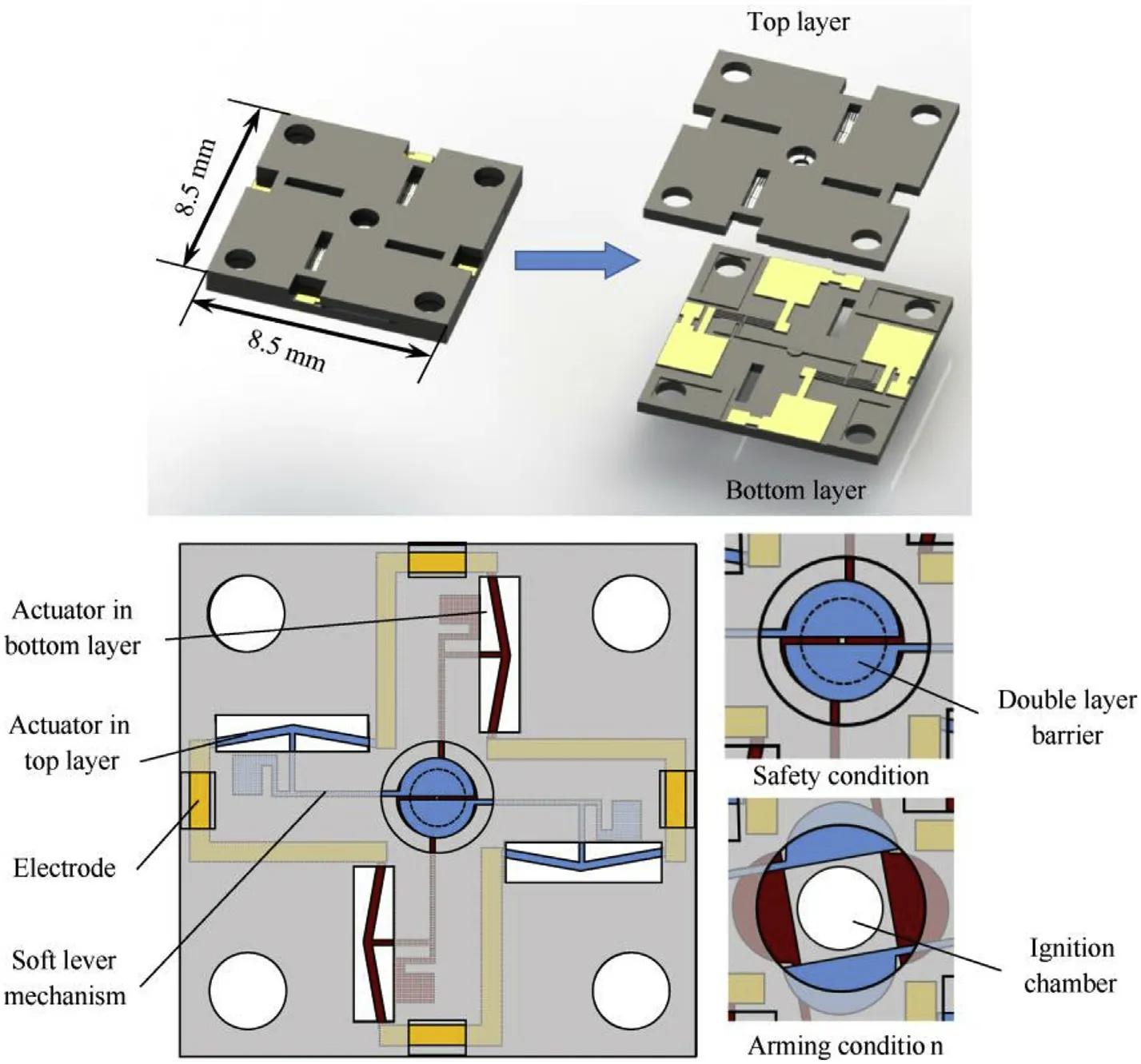
Fig.3.Structure of the S&A device.
The soft lever mechanism consists of a hard lever and two soft beams,and the barrier is placed on the end of the hard lever.One soft beam is fixed and the other one is connected to the actuator.The displacement of the barrier is enlarged due to the bending deformation of the soft silicon beam.The balance between the actuator"s out force and the soft lever"s driven force can be obtained by applying the following equations:

Here,d’is the displacement of the actuator with soft lever.Eis the Young"s modulus of silicon.Iis the moment of inertia,I=hw’3/12.Ldis the distance between two of the soft beams.Ais the crosssectional area of the actuator.The specific geometrical parameters of the soft lever mechanism are shown in Table 2 and presented in Fig.4.After the soft lever mechanism is integrated,the deformation of the actuator reduces from 18.8 μm to 18.6 μm,so the impact of the soft lever is nearly negligible.The enlarged proportion is 1:22,and the theoretical displacement of the barrier is 409 μm.
Finite element simulations of the actuator are carried out.Compared with theoretical analysis results,the simulation model considers the thermal boundary conditions of the handle layer and soft lever mechanism.Besides,the model fully considers silicon material parameters that vary along with the temperature,such as thermal conductivity,thermal expansion coefficient,and heat capacity.Fig.4 shows that the actuator can generate a displacement of 17.9 μm when the applied voltage is 10 V.After being enlarged by the soft lever mechanism,the displacement of the barrier is 374.9 μm,which enables the ignition chamber(250 μm radius)to be completely open.The highest temperature(1020 K)occurs in the center of the V-shape silicon beam,and the maximum stress(0.42 GPa)occurs at the ends of the actuator and the soft beam,which are sufficiently safe for the melting point and breaking strength of silicon.
2.3.Fundamental mechanism of the initiator
The structure of the initiator is shown in Fig.5.The initiator is a NiCr alloy bridge foil based on a glass substrate and covered with an Al/CuO energetic film[3,4].The overall size of it is 13.4×5×0.5 mm3.The bridge foil is a square bridge with a length of 380 μm to match the diameter of ignition chamber(500 μm).The energetic film is a multilayer Al/CuO composite film which generates thermite reaction under high temperature.Specific parameters are listed in Table 3.According to the reaction formula:2Al+3CuO=Al2O3+3Cu,the theoretically optimal proportion of the film"s thickness of Al and CuO is nearly 1:2,and thus we set the single layer thicknesses of Al and CuO at 25 nm and 50 nm[5].

Table 2Geometrical parameters of the soft lever mechanism.

Table 3Basic parameters of the initiator.
The working mechanism of the initiator is as follows:When an excitation voltage is applied,the bridge foil produces high temperature plasma to heat the energetic film,and the high temperature catalyzes the Al/CuO energetic film to generate a self-diffusion thermite reaction and produce a flame.After ignited,the bridge foil is fused,and the energetic film contributes to enhancing the energy output of the initiator.
2.4.Fundamental mechanism of the lead charge
To match the flame energy of the initiator,LTNR is chosen as the lead charge.The explosive chamber is filled with lead charge and placed on the top of the S&A device.However,the distance between the top surface of the S&A device and the barriers is 400 μm(thickness of the handle layer),too far for energy transfer.To shorten the distance,the lead charge is designed in a ladder shape,shown in Fig.6.The lead charge consists of a main body and a small ladder.The main body is a cylinder of Φ3 mm×3 mm.The small ladder with a diameter of 600 μm is slightly larger than the ignition chamber(500 μm).The distance between the barrier and the ladder"s surface is reduced to 50 μm,and the distance between the initiator and the ladder"s surface is reduced to 550 μm.The lead charge can effectively improve the efficiency of energy transfer and relieve performance restraints of the initiator.

Fig.4.Simulation result of the electro-thermal actuator.
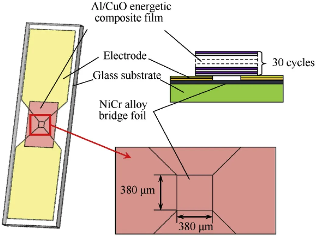
Fig.5.Structure of the initiator.
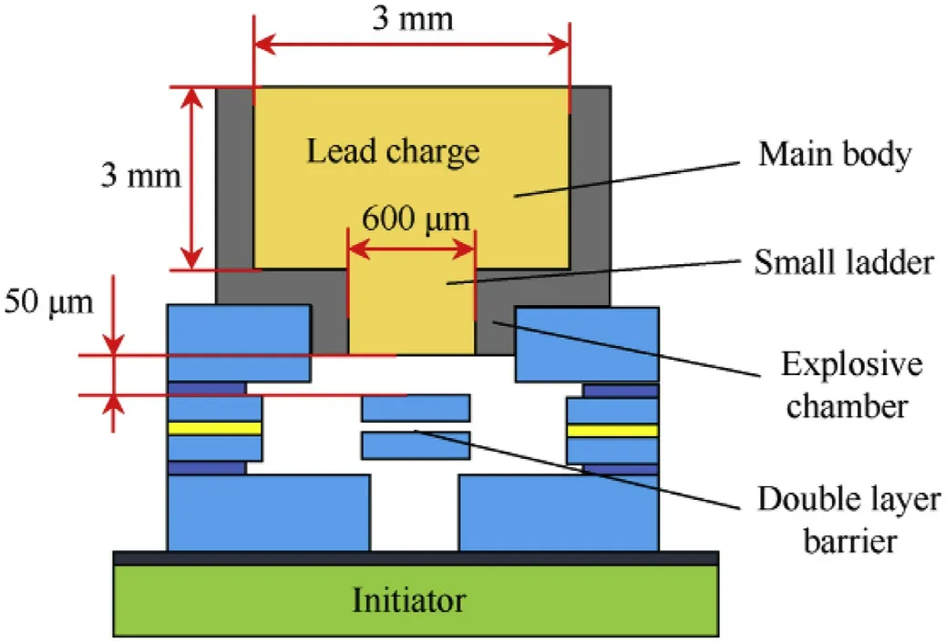
Fig.6.Structure of the lead charge.
3.Fabrication
3.1.Fabrication process for the S&A device
SOI wafers(50 μm device layer,3 μm buried layer,400 μm handle layer)are used to fabricate movable structures in the S&A device.The movable components are placed on the device layer with chambers in the handle layer for releasing moving components.The fabrication process is shown in Fig.7.The process is as follows:(a)Sputtering 50nmCr and 300nmAu on the top silicon wafer of the SOI silicon wafers to release electrodes;(b)Depositing 100 nm SiO2on the top silicon wafer using CVD process to protect the electrodes;(c)Sputtering 200nmAl on both sides for masking in the Deep Reactive Ion Etching(DRIE)process;(d)DRIE process etches the bottom silicon wafer with a depth of 400 μm to release moving parts of the top silicon wafer;(e)DRIE process etches the top silicon wafer with a depth of 50 μm;(f)Removing the aluminum mask and using HF wet etching to etch the SiO2sacrificial layer for the release process,and separate the movable top silicon part and fixed bottom silicon part.The S&A device consists of two layers of the SOI wafers,with the top layer covering the bottom one.The two layers are connected by using epoxy resin glue and solder paste.
3.2.Fabrication process for the initiator
The initiator consists of multiple layers of films,which are sputtered on a 500 μm glass substrate layer by layer.The fabrication process is shown in Fig.8.The process is as follows:(a)Sputtering 900 nm NiCr alloy as the bridge foil;(b)Sputtering 50 nm Cr and 300 nm Au to release electrodes;(c)Sputtering 100 nm SiO2to form an insulating layer between the bridge foil and the energetic film,and alternately sputtering 30 cycles of 25 nm Al and 50 nm Cu to form a 2.25 μm energetic film.The total thickness of the film is 3.6 μm.
3.3.Assembly of the MEMS pyrotechnic
The MEMS pyrotechnic is shown in Fig.9.The S&A device is placed on the upper surface of PCB and the initiator is assembled into the PCB from the backside.Relative positions of the three parts are fixed using pins,and their circuits are connected to one same plane through gold wires,as shown in Fig.9(a).The explosive chamber is fabricated by applying the conventional machining process and femtosecond laser process,and then filled with lead charge through the inkjet printing process,as shown in Fig.9(b).Finally,the lead charge is assembled to the higher end of the MEMS pyrotechnic to compose a highly-integrated device as shown in Fig.9(c).
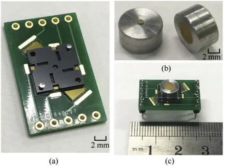
Fig.9.The MEMS pyrotechnic:(a)S&A device and initiator;(b)Lead charges;(c)The MEMS pyrotechnic.
4.Tests and discussions
4.1.Test of the condition-switching function
The basic function of the S&A device is to switch the MEMS pyrotechnic from safety condition to arming condition when the initiator is prepared for ignition.According to the driving principle,the four barriers need to be applied with an electrical signal to let the ignition chamber open.Displacement of the electro-thermal actuator is directly determined by the voltage of the electrical signal.Recorded by a high-speed camera,test results are shown in Fig.10.The barriers"displacement is almost proportional to the driving voltage,as shown in Fig.10(a).The theoretical and simulation results are close to experimental results.When no voltage is applied,the barriers cover the ignition chamber and the pyrotechnic is in the safety condition,as shown in Fig.10(b).To ensure that the ignition chamber can be completely open,the arming condition"s driving voltage is set to 10 V,and the barrier generates a displacement of 371.9 μm within 18 ms in the experiment,as shown in Fig.10(c).
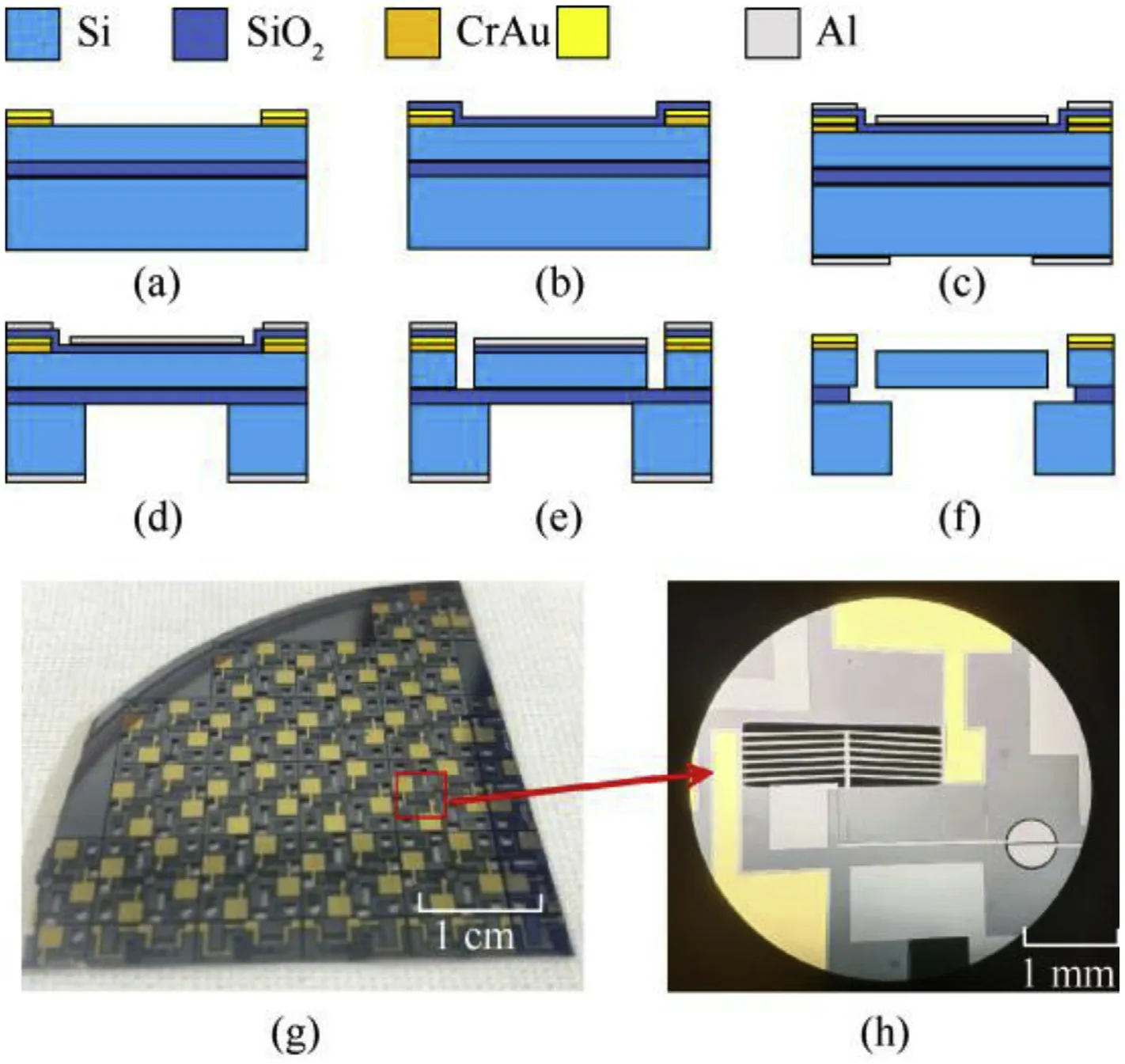
Fig.7.Fabrication process for the S&A device:(a)Sputtering electrodes;(b)Depositing SiO2;(c)Sputtering Al mask;(d)Handle layer etching;(e)Device layer etching;(f)Releasing;(g)S&A device wafer;(h)S&A device chip.
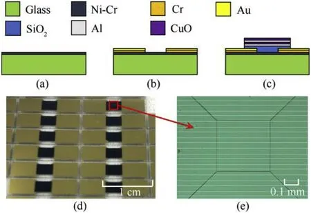
Fig.8.Fabrication process for the initiator:(a)Sputtering the bridge foil;(b)Sputtering electrodes;(c)Sputtering the energetic composite film;(d)The initiator chips;(e)The bridge foil.
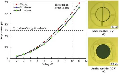
Fig.10.Test results of the condition-switching function.
4.2.Ignition test in the safety condition
The igniting function is realized by the initiator.When applied an excitation voltage,the initiator generates a flame through the NiCr bridge foil covered with an Al/CuO energetic film.The average resistance of the bridge foil is verified to be 3.2 Ω.An energy dispersive spectroscopy(EDS)analysis is then carried out in surface section(10×10 μm2area)of the Al/CuO energetic film.Test results in Fig.11 show that the mass ratios of oxygen,copper,and aluminum are respectively 19.40%,62.68%,and 17.92%,and the atomic ratios of the three elements are 42.35%,34.45%,and 23.20%.Due to the impact of vacuum level and surface oxidation,the ratio of oxygen is slightly higher than that of copper.The ratio of copper and aluminum is basically consistent with the designed value(3:2).
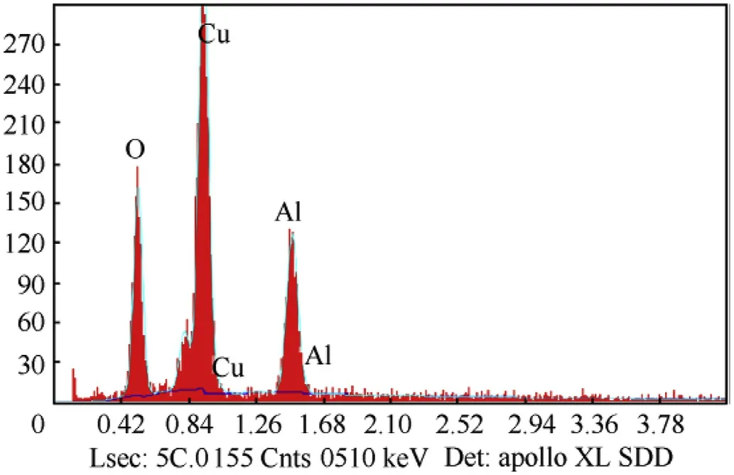
Fig.11.Results of the EDS analysis.
In the ignition test,the initiator is excited by a 47 μF capacitor discharging with a charging voltage of 60 V.The process of the flame being generated is recorded by a high-speed camera(77000 fps),and shown in Fig.12.When applied an excitation voltage,the NiCr bridge foil produces a flame and emits red light at first,the process of which lasts 52 μs.And later,the Al/CuO energetic film begins to react to the self-diffusion thermite reaction.The thermite reaction emits blue light,and the fire source is noticed to be diffusing from the center to the two sides.The reaction lasts 364 μs,and the whole ignition process lasts 416 μs.The height of the flame is much higher than 1 mm(the scale line shown in the background).It is adequate for the initiator to detonate the lead charge with the distance of 550 μm.
When the ignition test is carried out in the safety condition,the barriers cover the ignition chamber and block the flame.The experimental setup is shown in Fig.13(a).After charging the 47 μF capacitor with a voltage of 60 V,the initiator can be ignited by discharging the capacitor.The initiator"s current-voltage curve is recorded by using an oscilloscope,as shown in Fig.13(b).The maximum current is 17.3 A at 3.7 μs,and the maximum voltage is 40.6 V.The bridge foil is nearly fused at 50 μs,in accordance with the test results recorded by high-speed camera(the red light lasts 52 μs).The center of the device(without the lead charge)is shown in Fig.13(c),where we can find that the flame cannot go through the S&A device in safety condition.After six group tests with the lead charge assembled,no lead charges are detonated by the initiator.The barriers still keep intact structure and movable ability,as shown in additional video.Therefore,the strength of the barriers is enough to resist the impact of the flame.It is verified that the barriers in the S&A device can effectively prevent the initiator from detonating the lead charge in safety condition.
4.3.Ignition test in the arming condition

Fig.12.Process of the flame being generated.

Fig.13.Results of the ignition test in the safety condition:(a)Experimental setup;(b)Current-voltage curve of the initiator;(c)Center of the pyrotechnic(without the lead charge).
The S&A device always maintains the safety status when there is no signal input.Before the ignition test is carried out in the arming condition,the S&A device must drive its barriers to open the ignition chamber.The operation sequence,including switching the condition of the S&A device,charging the capacitor,and igniting the initiator,can be controlled by the microprocessor.The experimental setup is shown in Fig.14(a).The microprocessor can produce a square wave signal to control the operation status of the circuit with a supply voltage of 5 V.The high-level signal can conduct the circuit.Consistent with the ignition test in the safety condition,the initiator is ignited by a 47 μF capacitor discharging with a charging voltage of 60 V.According to the test of the condition-switching function,the supply voltage of the S&A device is set to 10 V.The timing diagram of the microprocessor is shown in Fig.14(b).According to the test mentioned above,the response time of the actuators is 18 ms and the ignition process can last 416 μs.Thus,to ensure that the ignition chamber can open completely and the bridge foil can be fused thoroughly,the condition switching time is set to 20 ms and the ignition process time is 1 ms.The center of the pyrotechnic(without the lead charge)is shown in Fig.14(c).It can be found that the flame can pass through the S&A device smoothly.With the lead charge assembled,the test result is shown in Fig.14(d).All MEMS pyrotechnics of the six groups are successfully detonated,and the whole bridge foil is thoroughly fused.The explosive chamber is broken after explosion,as shown in Fig.14(e).The test results verify that the initiator has the ability to detonate the lead charge in the arming condition.
5.Conclusions
(1)In this paper,we propose the design and characterization of a MEMS pyrotechnic with a double-layer barrier S&A device.The four barriers designed into a double-layer structure in the S&A device can effectively improve the reliability of the whole system.The barriers are driven by the V-shape electro-thermal actuators through a soft lever mechanism.When a voltage is applied on the actuators,the S&A device can actively switch the condition of the MEMS pyrotechnic from safety to arming with rapid response.The experimental results of the barriers"displacement are basically consistent with the theoretical and simulation results.When the applied voltage is set at 10 V,the barriers can generate a displacement of 371.9 μm within 18 ms,allowing the ignition chamber to open completely.
(2)The MEMS pyrotechnic integrates an initiator,S&A device,and lead charge.The initiator is a NiCr bridge foil covered with an Al/CuO energetic film,and the lead charge is LTNR.The initiator is ignited by the excitation of a 47 μF capacitor discharging with a charging voltage of 60 V.The discharging process nearly lasts 50 μs,and the flame nearly lasts 416 μs.The experiments are carried out in 12 groups(six groups in safety condition and six groups in arming condition).In the safety condition,the S&A device can prevent the flame from detonating the lead charge,and the barriers still keep intact structure and movable ability.In the arming condition,the initiator can detonate the lead charge successfully.Thus,the S&A device has the ability to control ignition properly while ensuring the safety of the weapon system.

Fig.14.Results of the ignition test in the arming condition:(a)Experimental setup;(b)Timing diagram of the microprocessor;(c)Center of the pyrotechnic(without the lead charge);(d)Result of the explosion test;(e)Explosive chamber after explosion.
Declaration of competing interest
The authors declare that they have no known competing financial interests or personal relationships that could have appeared to influence the work reported in this paper.
Acknowledgements
This work is supported by the National Key R&D Program of China(2017YFB1102900)and the Fundamental Research Funds for the Central Universities(xzy012019004).
Appendix A.Supplementary data
Supplementary data to this article can be found online at https://doi.org/10.1016/j.dt.2021.09.013.
杂志排行
Defence Technology的其它文章
- Modified couple stress and thickness-stretching included formulation of a sandwich micro shell subjected to electro-magnetic load resting on elastic foundation
- Recent advances in the synthesis and energetic properties of potassium-based potential green primary explosives
- Investigation of normal,lateral,and oblique impact of microscale projectiles into unidirectional glass/epoxy composites
- A quasi-isentropic model of a cylinder driven by aluminized explosives based on characteristic line analysis
- Kevlar fabric reinforced polybenzoxazine composites filled with silane treated microcrystalline cellulose in the interlayers:The next generation of multi-layered armor panels
- Experimental study on the cavity evolution and liquid spurt of hydrodynamic ram
