Steel rings as seismic fuses for enhancing ductility of cross braced frames
2022-10-19FarhadBehnamfarSaeidArmanandHassanZibasokhan
Farhad Behnamfar ,Saeid Arman and Hassan Zibasokhan
1.Department of Civil Engineering,Isfahan University of Technology,Isfahan 8415683111,Iran
2.Department of Civil Engineering,Kermanshah University of Technology,Kermanshah 6715685420,Iran
Abstract: A new remedy is proposed in this study to increase the ductility of cross-braced frames to a level comparable with ductile moment frames.The suggested system consists of one or two concentric steel rings installed in the cross-braced bay vertically.The steel rings are designed such that they fail in bending sooner than failure of the braces in compression.Then the rings act as seismic fuses with multiple bending plastic hinges.Using nonlinear static analysis,it is shown that the proposed system can be designed to behave like cross-braced frames with regard to stiffness and strength,and like special moment frames with regard to ductility.Seismic design factors for the proposed system are recommended based on nonlinear pushover and cyclic analysis studies.
Keywords: cross brace;special moment frame;steel ring;seismic fuse;ductility
1 Introduction
In highly seismic areas,there has always been a challenge between adopting special moment frames or special braced frames as seismic resistant steel structures.Moment frames are usually an ideal system regarding the architectural needs of any building.For structural engineers,however,it is not that ideal because it lacks enough lateral stiffness despite its large ductility in lateral motion.On the other hand,cross-braced frames accommodate a large lateral stiffness but cannot provide much ductility because of their inherent weakness in compression even when they are strong enough to enter the inelastic range without early buckling.To make use of the benefits of both systems concurrently in a single system,researchers have proposed several combined steel structural systems.A possible remedy has been the use of eccentric braced frames.In contrast,a large number of research works have been focused on enhancing the ductility of cross-braced frames one way or another without losing their beneficial stiffness and strength properties.The proposals have been mainly to increase the ductility capacity of cross braces whether by the use of frictional or yielding devices equally called seismic fuses.Different mechanisms are used in seismic fuses,including friction,yielding,etc.(Soong and Dargush,1997).A review of frictional dampers can be found elsewhere (Pall and Marsh,1982;Mualla and Belev,2002;Monir and Zeynali,2013;Leeet al.,2016;Tartagliaet al.,2021;Jaiseeet al.,2021).
Since they are relevant to the subject of the present research,yielding devices are the focus of this review.Yielding dampers can be categorized based on the dominant internal action which causes yielding (axial,shear,torsional,and flexural actions) or the location of the damper (at the base,at the beam-column connection,at the concentric braces,etc.).The contained core of buckling restrained braces yields due to the axial force of the brace (Blacket al.,2004;Alborziet al.,2019;Ghowsiet al.,2020;Pandikkadavath and Sahoo,2020).Shear panels with/without slit or perforation (Nakashimaet al.,1994;Hitaka and Matsui,2003;Formisanoet al.,2016),buckling restrained shear panels (Denget al.,2015) and steel shear links (Mahmoudiet al.,2019)use shear force as the dominant internal action to cause yielding in the damper.Torsional moment has been used to cause yielding by some researchers (Skinneret al.,1975;Vetr and Ghamari,2012;Mahyariet al.,2020).Bending moment is the most widely used mechanism to cause yielding in existing dampers (Kellyet al.,1972;Aguirre and Sanchez,1992;Tsaiet al.,1993;Grayet al.,2012;Zhenget al.,2015;Li and Shu,2020).Yielding steel dampers have been used in different locations in the structure,including at the base (Chenget al.,2008;Milani and Dicleli,2017;Manchalwar and Bakre,2020),at the beam-column connection (Caladoet al.,2013;Soltanabadi and Behnamfar,2018;Tagawaet al., 2020;Fathizadehet al.,2021;Khaliliet al.,2021),or in the concentric braces (Grayet al.,2012;Piedrafitaet al.,2013;Jiaet al.,2018;Zibasokhanet al.,2019).
Different dissipaters are used in the bracing system.In this regard,a U-shaped damper was proposed by Kellyet al.(1972) and investigated experimentally by Aguirre and Sánchez (1992).This damper was studied experimentally in the chevron bracing system by Echavarríaet al.(1996),diagonal bracing system by Leeet al.(2018),and base isolation system by Ohet al.(2013) and Manchalwar and Bakre (2020).Moreover,use of the added damping and stiffness (ADAS) damper was investigated by Bergmanet al.(1987) and extended by Whittakeret al.(1989).Triangular shaped plates were used in this damper (named as TADAS) by Tsaiet al.(1993) and investigated by other researchers (Mahmoudi and Abdi,2012;Mohammadiet al.,2017;Li and Shu,2020).This system is composed of several solid X (in ADAS) or V-shape (in TADAS) steel plates as dampers placed in a space prepared by distancing the top of a chevron bracing from the bottom of the story beam such that they bend inelastically about their weak axis when the story drifts under lateral loads.
Another enhanced damping system is the knee braced frame (KBF) proposed by Aristizábal-Ochoa (1986) and developed by Balendraet al.(1990) and other researchers such as Mahmoudiet al.(2018).It consists of a diagonal brace crossed almost perpendicularly near its upper end by a short steel link.The short link yields in bending before buckling of the brace and enhances ductility of the system.Due to the link element performing inevitably as a bearing member for at least the live gravity loads,and the extra forces it exerts to the column within its span,it may be used with caution.
Another yielding element placed in concentric braces is a pipe segment located at the end connection of a diagonal brace.It is placed such that the plane of its cross section is normal to the plane of the braced bay and the longitudinal axis of the pipe is perpendicular to the axis of the brace member.When the brace is under tension or compression,a wall of the pipe segment bends about its longitudinal axis.Such a bending capacity is taken to be attained under an axial force smaller than the buckling capacity of the brace to enhance the energy dissipation ability of the system.The pipe damper was proposed by Abbasnia and Vetr (2005).Afterwards,Kafi and Mojgani (2008) extended the above proposal by using two concentric pipe segments and reported a much larger system ductility.Cheraghi and Zahraei (2016)slightly varied the configuration proposed in (Kafi and Mojgani,2008) by making a small gap between the two pipes to control when the second pipe is activated.Naghipour and Salim-Bahrami (2015) changed the idea of double pipes by using a small rectangle instead of the exterior pipe for ease of construction.A practical limitation of the double-pipe system is limitation of availability of larger integral pipes for the exterior segment.As a solution,Andalibet al.(2018) replaced both pipe segments with a single circle composed of two half-circle parts built up using steel plates and bolted end joints.They discussed the good ductility and easy installation or replacement of their proposed system.Deihim and Kafi (2017) employed two supplementary steel plates in critical regions.
The dual pipe damper (DPD) was proposed by Maleki and Mahjoubi (2013) and Mahjoubi and Maleki(2016).When used with Chevron braces,this system is very similar to the ADAS system except that the steel plates are replaced by one or more sets of dual pipe segments.Each dual pipe is composed of two pipe segments placed in a direction normal to the braced bay and welded to each other.It was shown that the segments yielded in bending due to story drift and the energy dissipation capacity of the system was favorable.The friction damper of Pall and Marsh (1982) were used in the center of an X brace bay by Jurukovskiet al.(1988,1995).In this system,the cross braces arrive at the corners of a rectangle made from four connecting steel profiles,making the sides of the hollow rectangle.Therefore,each brace is cut short where it is connected to the central rectangular area enclosed by the peripheral members of the rectangle.The story drift makes all of the four members undergo a lateral relative displacement and bend bi-flexurally.Therefore,they can potentially develop eight plastic hinges that results in a large ductility capacity.Use of a single steel ring instead of the above rectangle for energy dissipation in bending was first proposed by Lohghalam (2003).Maleket al.(2006) and Pabesang (2006) studied this system under monotonic and cyclic loading and determined the energy dissipation capacity of the system.Other researchers have developed special yielding systems for use in the center of X braced frames including Ciampi and Ferreti(1990),Sabouri-Ghomi and Roufegarinezhad (2005)and Zahraei and BazHavaei (2008).
The present work is an extension of the idea presented in (Lohghalam,2003).Here,two steel rings are used at the center of the braced bay and the nonlinear behavior of the system is studied.Then the buckling modes of the system,in plane and out of plane,are investigated and a practical procedure for design of the proposed damping system is devised.
2 Proposed damping system
The suggested system is shown in Fig.1.One of the main advantages of the proposed system in comparison with a moment frame is the ability to be repaired after an earthquake.In moment frames,plastic hinges form in main members (mostly beams) and repairing the structure after an earthquake is very costly and,in many cases,not economically sound.

Fig.1 Suggested steel yielding damper
This system consists of two concentric rings preferably made of pipe sections added to the system in the plane of the braced bay.The plastic hinges form at the location of the maximum bending moment in the rings.As it will be seen,the maximum bending moments in the rings develop at the intersection with the braces.Due to the presence of interior and exterior braces,plastic hinges are formed in the vicinity of these braces.As shown in Fig.2,the system is designed such that each of the quarters of the rings develops two flexural hinges at its ends simultaneously.Therefore,the system at failure has developed 16 hinges instead of four in the corresponding moment frame and two in the associated concentric braced frame.It can then be anticipated that the proposed system has a large capacity of energy dissipation.This is only true if the braces are designed to remain elastic and unbuckled until failure of the system,and their resulting sections are affordable.This point will be clarified in the next sections.Note that there are four joints along the brace length.Only the connection of the brace to the beam-column joint can be hinged for the system to be stable.Design of the rings under the applied loads is discussed first,and then a buckling analysis of the braces will be investigated.
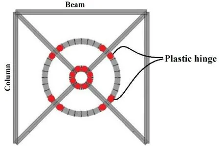
Fig.2 Plastic hinges developed during seismic loading
3 Design of the system
3.1 Internal loads of the rings
At each moment,the steel rings are under a pair of compressive loads along one diameter and a pair of tensile loads along the perpendicular diameter.The compressive and tensile loads are equal in value because the braces are designed not to buckle in any case.This is shown in Fig.3.
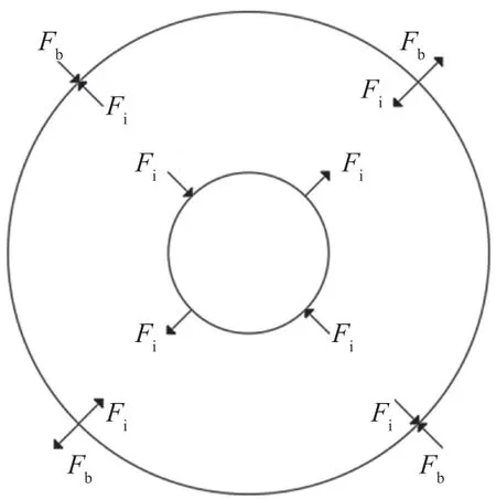
Fig.3 Pair of rings under axial forces of the braces
Then each ring can be analyzed under the resultant of the applied loads.Due to symmetry,analyzing only half of the ring is adequate with the boundary condition shown in Fig.4.
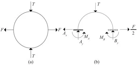
Fig.4 Analytical model of each ring: (a) applied loads(b) boundary conditions of the semi-circle
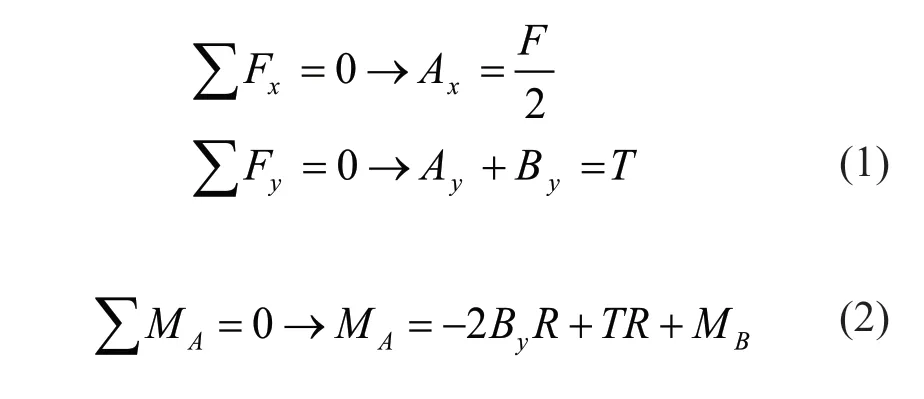
Then,the equilibrium equations of the semi-circle are:
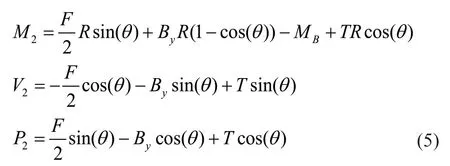
Similarly,for the internal forces of the semi-circle(Fig.5):

Fig.5 Internal reactions of the semi-circle
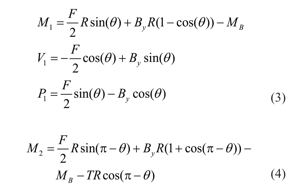
Noting sin(π-θ)=sin(θ) and cos(π-θ)=-cos(θ),then:
Using the Castigliano′s theorem:
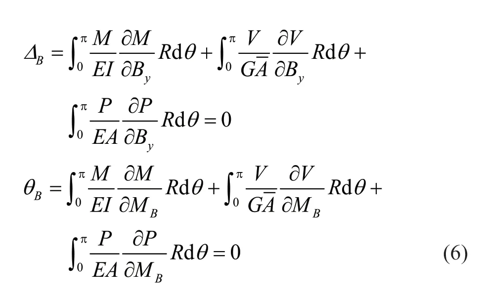
Solving the integrals of Eq.(6) results in relations for the bearing reactions as follows:

The maximum moment is calculated by integrating Eqs.(3) and (5) to occur at the point of application of the external load as:
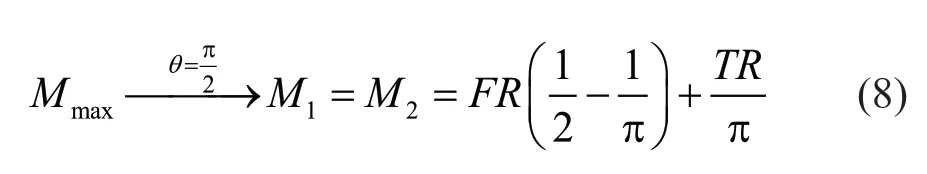
The point away from the lateral load (F) where the moment becomes zero can be found by double integration of the moment equation.It turns out that the moment vanishes at the following angle:

The results of the above analysis for reactions and bending moment of the semi-circle,assumingF=T,are shown in Fig.6.
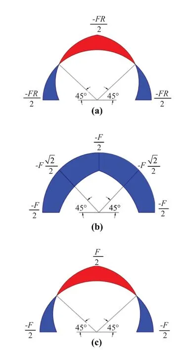
Fig.6 Results of analysis of the semi-circle: (a) bending moment;(b) shear force;(c) axial force
As seen in the figure,the maximum moments occur at the connections of the rings and braces.
Strictly speaking,the above relations should have been developed by considering the effect of the curved shape of the braces.Supplementary analysis shows that the difference in reactions is less than 4% when accounting for the curved shapes.Therefore,this task has been ignored in this study.
3.2 Stiffness of the rings
As will be seen in the latter sections,calculation of stiffness of the rings is necessary for deriving design formula for the braces.
The stiffness of each ring along the axis of a brace is calculated using the Castigliano′s theorem to determine the horizontal displacement of pointBin Fig.4(b) as follows:
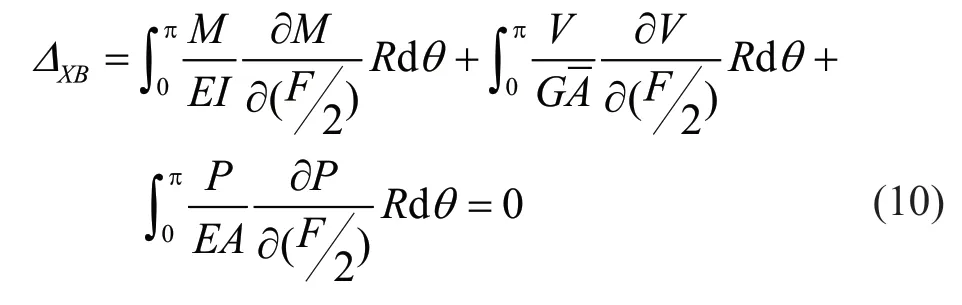
Using Eqs.(3) and (5),Eq.(10) is rewritten as:
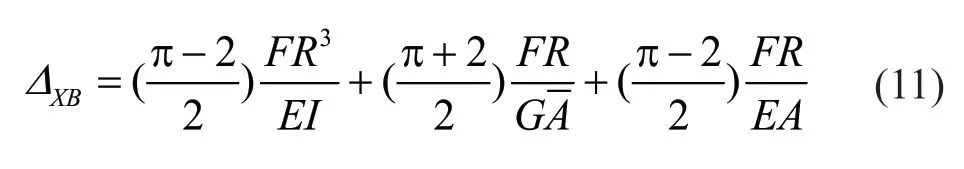
Then,the lateral stiffness of a complete circle (two times the value derived from Eq.(11)) is:
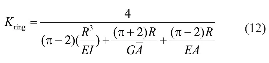
Different terms in the denominator of Eq.(12)include contribution of moment,shear and axial force,respectively.Then it can be rewritten as:

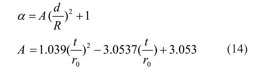
where the coefficientαrepresents how the lateral stiffness of the ring reduces due to shear and axial forces of the ring.
Figure 7 shows howαincreases withd/Randt/rowheredis diameter of the pipe section used for the ring,Ris radius of the ring,andtandroare the thickness and exterior radius of the pipe section,respectively.
As observed,α(shear and axial flexibility) increases with the increase ofd/Rand the decrease oft/roas expected.
By selecting several possible steel sections for the rings and doing a regression analysis,theαcoefficient can be calculated from the following equation with an extremely small error:
3.3 Lateral stiffness of the system
When the lateral stiffness of the rings is known,it is easy to calculate the lateral stiffness of the system.This parameter,K,is calculated using Fig.8.

Fig.8 Calculation of the lateral stiffness of the system
In Fig.7:
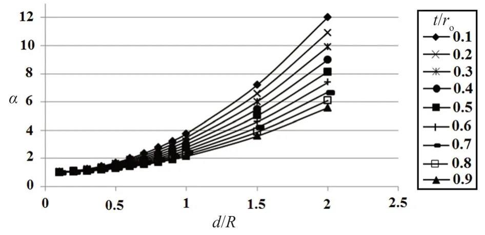
Fig.7 Variation of contribution of shear and axial flexibilities as represented by the common factor α

where:
and:
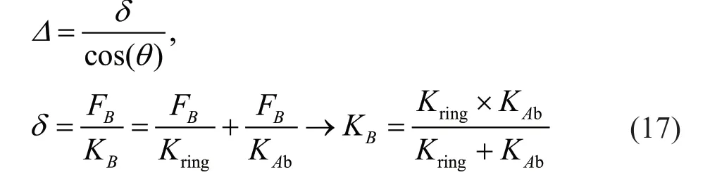
In the above equation,Kringis calculated using Eq.(13) andKAbis the axial stiffness of the exterior brace being equal toEAb/Le,whereEis its modulus of elasticity,Abis the cross section area of the brace,andLeis the effective length of the brace.
Substituting Eqs.(16) and (17) in Eq.(15) results in:

3.4 Design of the rings
According to Fig.3,if a portion of the braces located between the two rings is supposed to be rigid against axial force,the lateral load is distributed based on the relative stiffness of the rings as:

whereFb,FiandFeare the axial force of the brace and the net lateral forces of the interior and exterior rings,respectively.Also,KiandKeare the lateral stiffnesses of the same rings.
According to Fig.6(a) and Eqs.(13),(19),and (20),the ratio of the maximum moments in the rings is:

whereMpis the plastic moment (reduced due to the axial force),Ris radius andIis the moment of inertia of the cross section,and the indices i and e refer to the interior and exterior rings,respectively.For a compact section,Mp=Z(Fy-fa) whereZis the plastic section modulus,Fyis the yield stress,andfais the axial stress.Then Eq.(21)is simplified to:

Numerical evaluation shows that the effect of neglecting the axial stress in the numerator and denominator of the fraction on the left of Eq.(22) is negligible.If the section and geometrical properties of the rings obey Eq.(22),it is expected that all of the plastic hinges form simultaneously.
3.5 Design equations of the braces
The braces are designed such that they do not buckle until a plastic mechanism forms in the system.At that time,the axial force of the exterior portion of the brace,where the same force is largest,must be smaller than the buckling force,or:
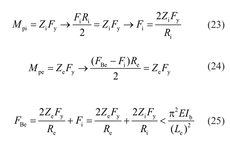
whereFBeis the axial capacity of the brace due to steel rings,Leis the effective length of the brace equal to the product of the effective buckling length factorkand length of the braceL(Le=kL),andIbis the cross section moment of inertia of the brace.
Using the coefficient for the expected yield stress,Ryand for overstrength of the section,Cpr(AISC 341-16,2016),the following equations can be developed for design of the braces not to buckle and not to yield as:
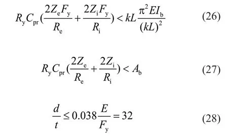
whereAbandLare the cross section area and length of the exterior brace.kis the effective buckling length factor to be calculated in the following.The third equation is for prevention of local buckling.
3.6 Determining the effective buckling length of the braces
For design of the braces according to Eq.(26),the effective buckling length factor,kshould be known.As mentioned in Section 2,the exterior brace is hinged at its upper connection.It has a rigid connection to the exterior ring.As the ring can move and rotate in plane as well as out of plane,the model shown in Fig.9 is drawn for calculation ofk.
The lateral and rotational springs in the above figure are to model the restraints provided by the rings and other braces against buckling of an exterior brace.The reactions and internal forces of the system of Fig.9 after buckling are shown in Fig.10.

Fig.9 Mathematical model for determination of k-factor of the braces
The differential equation governing the system of Fig.10 and its solution are:
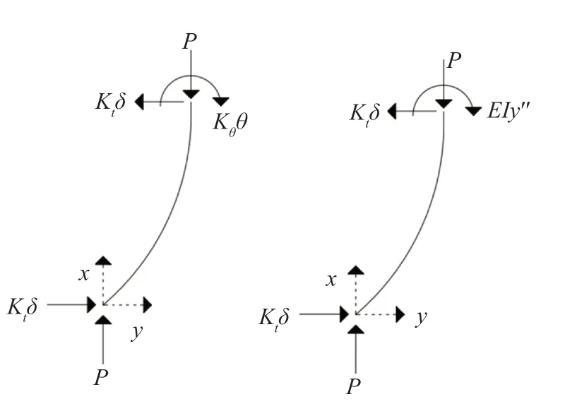
Fig.10 End reactions and internal forces of the exterior brace after buckling
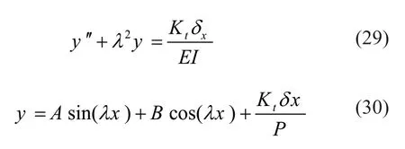
whereλ2=P/EIandP=Fb,I=moment of inertia of the brace section andEis its modulus of elasticity.
Using the existing boundary conditions,a characteristic equation is obtained as:
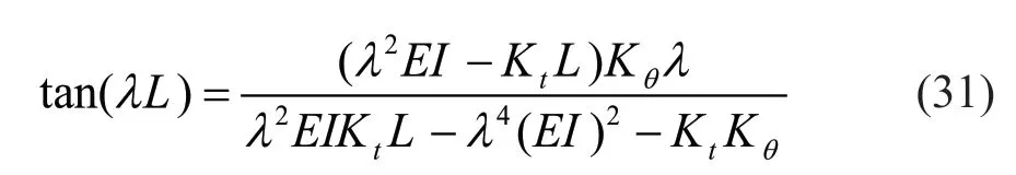
that can be solved by trial.When the minimumλis known from Eq.(31),then thek-factor is calculated ask=π/λL.In Eq.(31) whenKt=0 andKθ→∞,λL=π/2 andK=2 that is equivalent to thek-factor for a column hinged at one end and roller clamped at the other end as expected.On the other hand,whenKt→∞ andKθ→∞,λL=4.49 andk=0.7 similar to the one for a column hinged at one end and clamped at the other end that is correct.Overall,Eq.(31) results in thek-value being a value between 0.7 and 2.
Equation (31) can only be solved when values ofKtandKθare known for in-plane and out-of-plane buckling of the braces as follows.
3.6.1 End restraint for in-plane buckling
The system after in-plane buckling of the compressive braces is shown in Fig.11.
According to Fig.11,lateral stiffness of three exterior braces should be combined as parallel springs and axial stiffness of the exterior ring should be accounted for as a spring in series with the previous one for calculating the spring stiffnessKt,as:
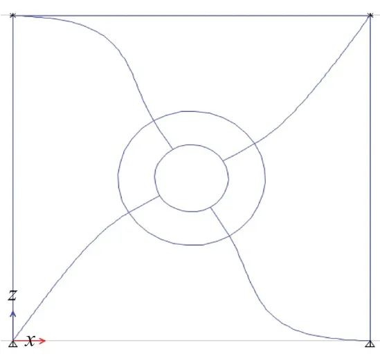
Fig.11 In-plane buckling of the system braces
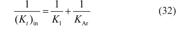
where (Kt)inis the in-plane stiffness of the lateral springKt,Klis the combined lateral stiffness of three exterior braces (=3×3EI/lb3,lb=length of the exterior brace),andKAris the axial stiffness of the exterior rings.Using the Castigliano′s theorem,it can be shown that:

The rotational spring stiffness,Kθsimulates the bending stiffness of the ring.It is calculated using the model of Fig.12.

Fig.12 Mathematical model for calculating Kθ in-plane
Of course,the bending stiffness of the interior brace is also important,but it is added separately to keep it simple.Using the same theorem,it is calculated as:
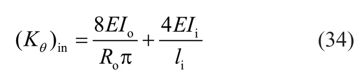
whereRo,IoandEare the radius,moment of inertia and modulus of elasticity of the exterior ring,Iiandliare the moment of inertia and length of the interior brace,and(Kθ)inis value ofKθin plane.
3.6.2 End restraints for out-of-plane buckling
The system after buckling toward out of plane is shown in Fig.13.

Fig.13 Out-of-plane buckling configuration of the system
Against such a buckling,the lateral springKtconsists partially of the lateral stiffness of one exterior brace,and torsional stiffnesses of the two tensile braces acting in parallel as shown in Fig.14.

Fig.14 Lateral and torsional stiffnesses of three braces against buckling of the fourth brace
They are combined in the spring stiffness,Koutusing equilibrium:
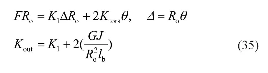
whereJis the torsion constant of brace.
The above parallel springs act in series with the outof-plane bending stiffness of a semi-ring in parallel with the same stiffness component of the interior brace as:
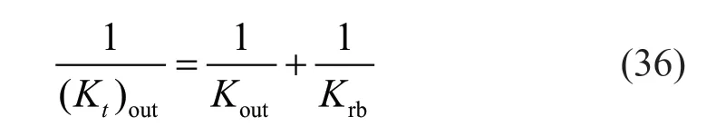
where (Kt)outis the lateral spring stiffness in the out-ofplane direction andKrbis the bending stiffness of a semiring in the same direction that can be shown to be equal to:
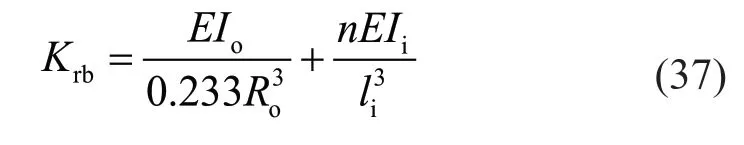
whereIiandliare the moment of inertia and length of the interior brace and 3 <n< 12 based on the bending stiffness of the interior ring.It is approximately taken to be the average value of 7.
The rotational springKθin the out-of-plane direction,(Kθ)outrepresents the torsional stiffness of a semi-ring.It can be shown to be equal to:
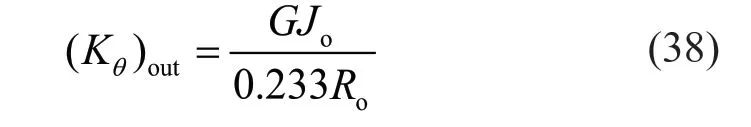
whereGandJoare the shear modulus and the torsion constant of the exterior ring,respectively.
3.7 Accuracy of the k-factor formula
To verify the accuracy of the formula derived for the effective buckling length derived in the previous sections,several practical examples are selected as summarized in Table 1.The samples are assumed to be made of mild steel with modulus of elasticity of 200 GPa and Poisson′s ratio of 0.3.
Thek-factor is calculated using both the developed equations and ABAQUS software (ABAQUS Inc.,2014).The results are gathered in Table 2.They show a proper accuracy.
It seems that in practice the out-of-plane buckling is usually the governing mode.Two points should be noticed here:
1) Because larger torsional rigidity of the braces enhances the buckling capacity of the brace,their section should be selected from closed profiles like box or better,pipe.
2) At the final point of lateral movement when a plastic mechanism has been developed due to formation of 16 hinges at the ends of each quarter-circle,there is no rotational stiffness in the rings to contribute toKθin Fig.9.Therefore,the first term on the right side of Eq.(34)should not be used when determiningKθfor the in-planek-factor calculation.
4 Nonlinear analysis outline
For the seismic design of the proposed system,it is necessary to investigate its seismic behavior.The lateral behavior of the proposed system is compared with the conventional X-braced and moment frames.Based on this comparison,the design parameters of the proposed system are determined including the response modification,overstrength and displacement amplification factors.These parameters can only be calculated by nonlinear analysis.Monotonic and cyclic nonlinear analysis are performed on a single-story single-bay frame being 3 m both in span and height.The procedure is started by selecting a number of choices for the steel pipe rings.Then the developed design formulas are followed to determine the sections of the braces,beam and columns.Then the nonlinear model of the designed system is analyzed and the ductility factor is calculated.
For the selected frames,the geometrical properties given in Table 3 are examined.For the X-braced frame,the brace is of the pipe section withd=70 mm andt=10 mm,and the beam and column sections are IPE200 and IPB200,respectively.The beam and column sections of the moment frame are IPE300 and IPB300,respectively.
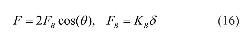
The appropriate sections for the braces are calculated by Eqs.(26) and (27).Then the system is analyzed under the lateral loadP=2Fccos(θ) as well as a vertical loadqand the beam and column sections are determined.Here,Fcis the axial capacity of braces in compression,θis the inclination angle of each brace with regard to the horizontal line andqis the vertical load per unit length that is conventionally taken to be 40 kN/m.
The system of Fig.1 composed of the members listed in Table 3,is analyzed nonlinearly in OpenSees(McKennaet al.,2017).Among the possible options,the distributed plasticity case is chosen for nonlinear modeling.In this case,each member is considered to be composed of several nonlinear fibers along its longitudinal axis.The nonlinear action in each section begins when the tensile or compressive strain reaches the values at yield.Then,it will be only necessary and enough to introduce a one-dimensional stressstrain relation for the steel material.Again,for such a definition,there are several choices within OpenSees.Based on experience,the Steel02 material is taken up for its stability and accuracy.In Fig.15,the Steel02 material is introduced along with the exact stress-strain relation of steel.The steel type is this figure is St37 with the yield stressFybeing equal to 240 MPa.

Table 1 Example cases for k-factor determination

Table 2 Values of the k-factor (N.mm)

Table 3 Geometrical properties of the frames having added rings
The slope of the second line in Fig.15 is 0.00658EwhereEis the steel′s modulus of elasticity and considered as 200 GPa.Poisson′s ratio is also considered as 0.3 for steel.The second branch of the Steel02 stress-strain relation terminates at the strain 0.1 where the section begins necking.This is equivalent to strength and stiffness degradation because the software removes such fibers from the section.Since design of the proposed system in Section 3 was arranged such that the nonlinear behavior of all the plastic hinges occurs more or less concurrently,it is anticipated that the extreme strain in all of the hinges reaches the point of necking at about the same time.Then,the whole system begins to decline as the lateral force-displacement diagram will tend to have an increasing negative slope from that point onward.It was found that the final reliable point of behavior of the system will be when strain at the first fiber among the sections becomes equal to 0.1.This decisive point is considered in the following calculations.To perform a comparative analysis,nonlinear behavior of the proposed system and its X-braced and moment frame counterparts are calculated.To make it easier to focus only on the effects of the addition of steel rings,the beam,column,and brace elements are taken to be the same between the frames with the proposed system.This is equivalent to the design of the X-braced system for the same lateral force mentioned above (2Fccos(θ)).Of course if the moment frame is designed for this force,heavier beam and column section will be derived.
5 Calculation of the seismic design parameters
5.1 Introduction
Two procedures are followed in this section to calculate the design parameters of the proposed system in comparison with the conventional braced and moment frames.First,the lateral behavior of the systems is determined until the point of degradation using a monotonic loading.The response modification factor(or theR-factor) is then calculated as the lateral force which displaces the system to a position corresponding to the starting point of degradation with elastic behavior,by the one where the nonlinear behavior begins.This is shown in Fig.16.
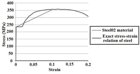
Fig.15 Stress-strain relation of St37 steel
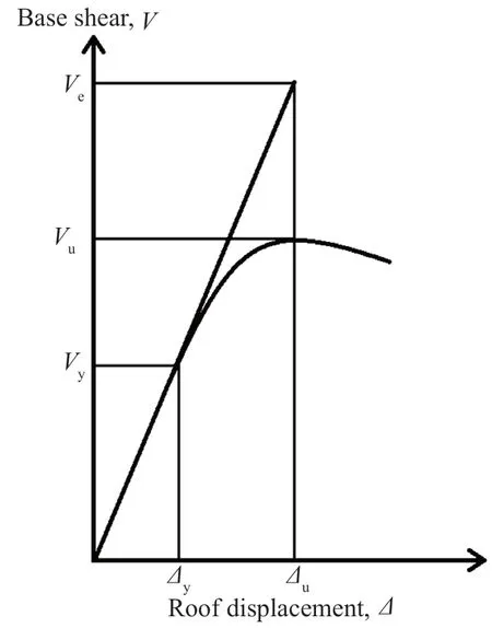
Fig.16 Calculation of the seismic design parameters
In the above figure:
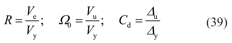
whereR,Ω0,andCdare the response modification,overstrength,and displacement amplification factors,respectively.The above parameters are calculated for each system separately and then the ratio of the values determined for the proposed system to the other two systems is calculated.The computed ratios are multiplied by the values of the design parameters of X-braced and moment frame systems,mentioned in a sample seismic design code,to arrive at the design values for the suggested system.
In the second procedure,a cyclic loading is applied to the system and its cyclic behavior is examined up to the point of degradation.Ratios of the areas enclosed by the hysteresis curves are used in a similar manner as above to calculate theR-factor.
At this point it should be mentioned that here the nominal response modification factorRof the proposed system and the conventional X-braced and moment frame systems are only calculated to compare them with each other on the same basis,not to necessarily use the calculated values for design.Then,it is to investigate the structural behavior of these systems comparatively and is not intended to determine the exact value of theR-factor.Determining the exact value of the response modification factor for the systems needs a comprehensive dynamic analysis and consideration of the soil conditions.
5.2 Numerical results
5.2.1 Verification
To verify the adequacy of the nonlinear models created in OpenSees,the cyclic results of the first sample in Table 3 is compared with the result of ABAQUS software.The specification of the sample D60-48 is shown in Table 3.About 1000 B32 quadratic beam elements each with a size of about 25 mm are used in the FE modeling.Nonlinear plastic material with von Mises yielding criteria and kinematic strain hardening is adopted for the stress strain curve of steel of the sample shown in Fig.15.The cyclic load-displacement results of two numerical models are compared in Fig.17.There is a good agreement between the results as seen in the figure.
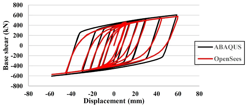
Fig.17 Comparison between cyclic results of OpenSees and ABAQUS numerical models for D60-48
5.2.2 Push-over analysis
The results of the push-over analysis of the three systems listed in Table 3 is shown in Fig.18.
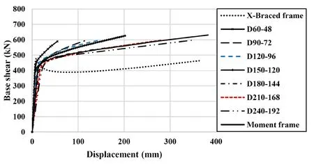
Fig.18 Push-over analysis of the frames
Using Eq.(39),the seismic behavior parameters of the systems are calculated and listed in Table 4.In this table,the amount of elastic lateral stiffness,K,of the frames can also be seen.Comparison of the lateral stiffness of the samples demonstrates that the stiffness of the proposed system varies between MRF and X-brace systems.Lateral stiffness of the proposed system increases with growth in the cross-section of the rings.In any case,since all specimens are designed for almost the same lateral force,the size of the beams and columns of the moment frame are much larger than the braced frames.
Ratios of the values calculated for the proposed system to those of the other systems and their averages are shown in Table 5.
According to the average ratios of Table 5,R factor equals 0.678×8=5.42 with regard to the moment frame and 1.425×6=8.55 with regard to the braced frame.The average of these values isR=6.98 for the proposed system.Moreover,Ω0equals 0.76×3=2.28 with regard to the moment frame and 1.18×2=2.36 with regard to the braced frame.These values are quite close and their average isΩ0=2.32 for the system handoff interest.Also,Cdequals 0.84×5.5=4.62 regarding the moment frame and 1.337×5=6.685 with regard to the braced frame.The average of the values isCd=5.65 for the suggested system.
5.2.3 Cyclic analysis
For cyclic analysis,the SAC loading protocol mentioned in AISC 341-16 (2016) is utilized.It is depicted in Fig.19.

Fig.19 Cycling loading protocol (AISC 341-16,2016)
The results of the cyclic analysis are shown in Fig.20.In addition,the ratio of the areas enclosed by the hysteresis curves of the proposed and the other systems,multiplied by the code-value of theRfactor of each system,is given in Table 6.The calculated values are estimated quantities of theRvalue of the proposed system.TheRfactor of special concentric bracing and moment frame systems is given by ASCE7-16 (2016) as 6 and 8,respectively.

Fig.20 Hysteresis curves of the system
As can be seen in this table,energy capacity of the proposed system is more than the X-braced frame in all cases.According to the average ratios of Table 6,theRfactor equals 0.46×8=3.68 with regard to the moment frame and 1.71×6=10.26 with regard to the braced frame,based on cyclic analysis.The average of these values isR=6.97 for the proposed system using cyclic analysis.As seen,theR-factor calculated using the cyclic analysis is similar to the one from push-over analysis,i.e.,6.13.The averageRfactor between the two analyses is 6.5.
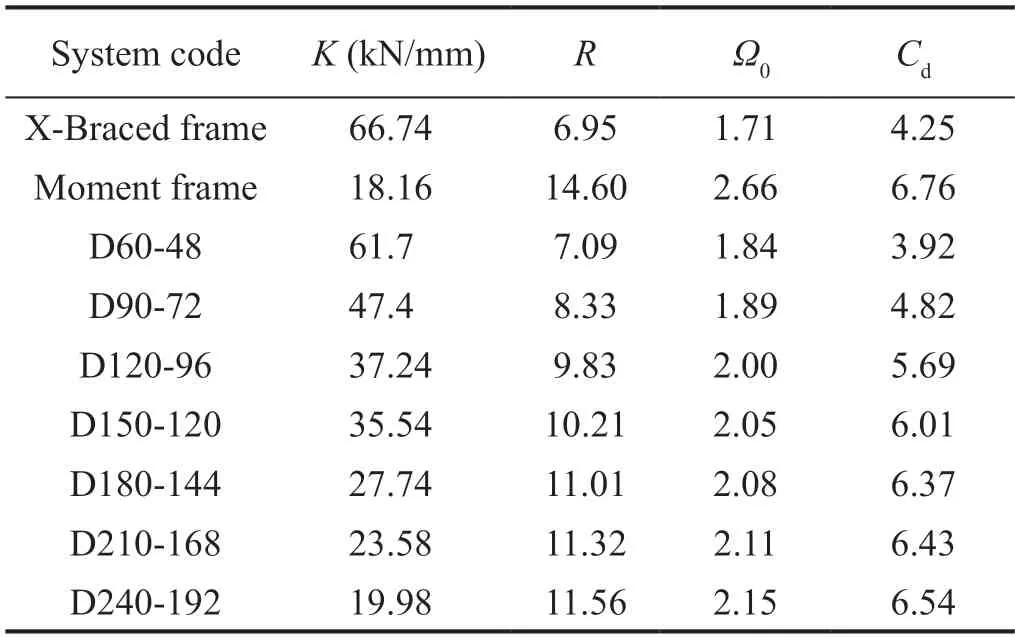
Table 4 Seismic behavior parameters
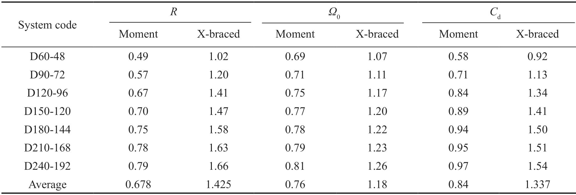
Table 5 Ratios of the values of the suggested system to the ones for the mentioned systems using push over analysis
5.2.4 Values of the parameters
Although determination of the exact values of the seismic design parameters for the proposed system requires further studies,the following values emerge temporarily based on the above calculations:
R=6.5,Ω0=2.4,Cd=5.5
SinceRμequalsR/Ω0,it equals 2.7 for the proposed system and 2.67 as recommended by ASCE7-16 (2016)for special moment frames.Then the above values show that the proposed system is almost as ductile as a specialmoment frame.Moreover,the value of this parameter for the special moment frame of this study,according to Table 3,is 5.49,which is almost twice the value obtained for the proposed system.In addition,the proposed system is more similar to eccentric braced systems regarding other parameters.
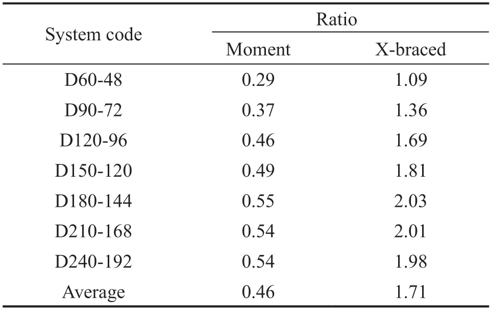
Table 6 Ratios of areas enclosed by hysteresis curves of the proposed and other systems
6 Conclusions
In this study,a new lateral bearing system was introduced in which two steel rings have been added to a truncated X-braced frame to accommodate the system with much larger energy dissipation capacity.To make the steel rings act as seismic fuses,other structural members of the system were designed based on the capacity design approach.The design equations for strength and stiffness of the proposed system were completely derived by the authors.The seismic behavior of the proposed system was investigated and compared with conventional X-braced and moment frames by performing nonlinear analysis.The seismic design factors of the system were calculated for comparison purposes through push-over and cyclic analysis.The results show that the proposed system can be designed to behave similar to a braced frame with regard to lateral stiffness,and to a special moment frame with regard to ductility.Some recommendations were provided for seismic parameters of the proposed system,including the response modification,overstrength and displacement amplification factors.
杂志排行
Earthquake Engineering and Engineering Vibration的其它文章
- Seismic response of selective pallet racks isolated with friction pendulum bearing system
- Reliability and sensitivity analysis of wedge stability in the abutments of an arch dam using artificial neural network
- Study on time-varying seismic vulnerability and analysis of ECC-RC composite piers using high strength reinforcement bars in offshore environment
- Optimization of design parameters for controlled rocking steel braced dual-frames
- Effects of timber infill walls on the seismic behavior of traditional Chinese timber frames
- Innovative mitigation method for buried pipelines crossing faults