Innovative mitigation method for buried pipelines crossing faults
2022-10-19MahdiRojhaniMajidMoradiandAliDerakhshani
Mahdi Rojhani ,Majid Moradi and Ali Derakhshani
1.Department of Civil Engineering,Faculty of Engineering,Shahed University,Tehran,Iran
2.Faculty of Civil Engineering,College of Engineering,University of Tehran,Tehran,Iran
Abstract: A new remediation technique is proposed to mitigate large deformations imposed on buried pipeline systems subject to permanent ground deformation.With this technique,low-density gravel (LDG) with high porosity,such as pumice,is used as backfill in the trench containing the pipe near an area susceptible to PGD.This countermeasure decreases soil resistance,soil-pipe interaction forces and strain on the pipe as the pipeline deformation mechanism changes to a more desirable shape.Expanded polystyrene geofoam has been introduced to decrease the density of the pipeline backfill;however,LDG is more efficient regarding workability during construction,environmental effects,durability,fire safety,and cost-effectiveness.A series of centrifuge model experiments in which the pipelines were subjected to reverse faulting was conducted to evaluate the proposed method.During faulting,the axial and bending strain and pipe deflection were measured.A comparison of the responses of the remediated pipeline and the pipeline without remediation indicates that the proposed technique substantially mitigates the effects of large deformation.
Keywords: pipelines;centrifuge modeling;faulting;mitigation;earthquake
1 Introduction
Protection of buried pipelines is required to guard these essential lifelines during earthquakes.Maintaining the serviceability of city lifelines containing gas,water and oil is vital to rapid recovery after natural disasters.One important cause of damage to pipelines during seismic events is permanent ground deformation (PGD),such as fault rupture and lateral spreading (Ashford and Juirnarongrit,2002).PGD in the soil imposes a considerable strain on pipelines,which can lead to their deformation and consequent breakage.Seismic ground faulting is a concentrated PGD that presents a severe hazard for continuously buried pipelines.Three types of earthquake faults exist: strike-slip,normal and reverse(Fig.1).Also,an oblique fault is a combination of a strike-slip fault and a normal or reverse fault.

Fig.1 Fault types: (a) strike-slip;(b) normal;(c) reverse
The occurrence of an earthquake is one of the main causes of damage to pipelines (Kianiet al.,2019;Shanget al.,2019;Darliet al.,2021;Xueet al.,2021).Some of the major examples of this type of damage are: the damage sustained by San Francisco′s water supply network during the 1906 earthquake;the damage to embedded pipelines caused by normal faulting during 1999 Chi-Chi earthquake;the strike-slip faulting in the 1999 Izmit earthquake in Turkey,which caused a 3 m offset in a 2.2 m diameter pipeline (Fig.2);and the reverse faulting that took place during the 1990 Manjil earthquake in Iran,which led to the buckling of water supply pipelines.Many studies have set out to assess how pipelines react to seismic faulting.Newmark and Hall (1975),Kennedyet al.(1977) and Takadaet al.(2001) established the groundwork for analytical studies on the subject.Meyersohn (1991) used Unipip finite element software to measure pipe strain.Liu and O′Rourke (1997),Xieet al.(2011 and 2013),Vasileiadis(2012),Khaksaret al.(2018) and Kouretziset al.(2014) conducted numerical and analytical studies on the response of continuous pipelines.Karamitroset al.(2011) and Vazouraset al.(2012) also conducted analytical studies on the subject.Ni and Mangalathu(2018) proposed a method based on dissipated energy to estimate the strains on pipes when subjected to normal faults.Niet al.(2020) carried out fragility analyses of buried pipelines due to fault displacements.The performance of pipes at fault crossings was numerically assessed by Melissianoset al.(2017) and Gantes and Bouckovalas (2013).It is necessary to verify research findings by comparison with the actual behavior of pipelines.There are no well-documented records of field cases of pipeline failure under faulting.Furthermore,complex facilities associated with expensive costs and effort are necessary for a full-scale physical simulation of pipelines (e.g.,Takada,1984;Mehrjardiet al.,2012;Fenget al.,2015;Sarvaniset al.,2018).These problems have made experimental modeling the best approach available to study and validate the effects of faulting on pipelines(Haet al.,2008a).It is noteworthy that the accuracy of laboratory tests is subjected to assumptions regarding length scale,boundary condition,soil condition,and so on,involved in modeling.Even the advanced centrifuge modeling technique is associated with a number of limitations such as errors related to the scale of soil particles,acceleration variation (due to radius change),Coriolis acceleration,and the acceleration field of Earth′s gravity.
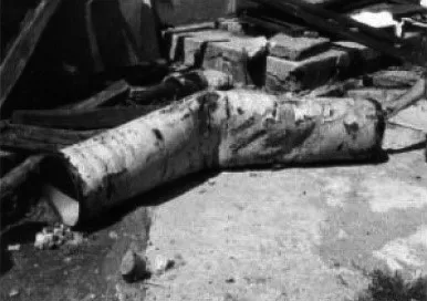
Fig.2 Pipeline damaged by faulting during the 1999 Izmit earthquake in Turkey (Eidinger et al.,2002)
O′Rourkeet al.(2005),Haet al.(2006) and Saiyaret al.(2015) performed centrifuge modeling on pipelines subjected to faulting.The pipe′s reaction under normal and strike-slip faulting was evaluated in their studies in which the deformation fault angles had been limited to 90° in all tests (Haet al.,2008b).Yoshizakiet al.(2001) carried out similar studies during a US-Japan cooperative research study.Other deformation angles were covered by Rojhaniet al.(2012),Moradiet al.(2013) and Khaksaret al.(2018) by means of their centrifuge models of pipelines subjected to normal and reverse faulting.Abdounet al.(2009) assessed the effects of several parameters on the response of buried pipelines subjected to strike-slip faulting.The factors evaluated using centrifuge model tests included soil moisture content,fault offset rate,relative burial depth,and pipe diameter.Different methods have been suggested for the mitigation of pipeline damage.Some relate to isolation or rerouting of pipelines around regions susceptible to damaging ground movement.Others pertain to the pipelines themselves,including the use of high strength or highly ductile materials and joints with enhanced expansion/contraction or rotation capabilities (O′Rourke and Liu,2012;Tsaiet al.,2015;Qin and Ni,2019).Isenberg and Richardson (1989),Ballantyne (1992) and Wang (1994) have suggested flexible joints to mitigate large ground deformation.
The properties of the backfill in pipeline trenches also can be modified for remediation purposes.Mehrjardiet al.(2012) proposed the use of geocell reinforcement with rubber-soil mixtures for mitigating the deformations of buried pipes and the settlement of backfill under repeated loading.Additionally,two series of threedimensional,full-scale tests conducted by Mehrjardiet al.(2012) to investigate the pipe response in a geocellreinforced trench considered the effects of compaction.In addition,Hegde and Sitharam (2015) investigated the suitability of geocell-reinforced sand beds to protect underground pipelines through laboratory tests and numerical analyses.
Meguid and Youssef (2018) performed an experimental study to measure earth pressure distribution on a pipe embedded in granular material with tire-derived aggregate backfill.They showed that the presence of a tire-derived aggregate above the pipe results in the reduction of vertical loads on the pipe.Niet al.(2018)studied backfilling the pipeline trench by using a tirederived aggregate as a seismic mitigation measure.They reported that this method is more effective than other common mitigation approaches.
Gantes and Melissianos (2016) reviewed several mitigating measures at pipe-fault crossings.They compared the effectiveness and applicability of conventional measures used in engineering practices or those that have been proposed in the literature,via numerical modeling.Witthoeft and Kim (2016) studied the use of EPS geofoam panels placed over underground pipes by employing numerical analysis.Application of EPS panels with different sizes was evaluated to determine the optimal geometry of the panels.
In an experimental study,Chooet al.(2007)examined a remediation method in which EPS geofoam blocks were used as low-density backfill.In this method,the split container was filled by sand,after which it was compacted to the desired level.After compaction,sand around the pipe was excavated and geofoam blocks with dimensions of 8.2×12.3×2.5 cm3,which simulate geofoam blocks with dimensions of 1×1.5×0.305 m3at a g level of 12.2,were set around the pipe.The gaps between the geofoam blocks were filled with compacted sand.This remediation technique was successful in reducing peak force in soil-pipe interaction and peak stress in the pipe.However,the type of backfill material and its environmental effect,durability,dimensions,and workability (the difficult process of setting EPS geofoam blocks into the soil) are the main disadvantages of the proposed remediation method offered by Chooet al.(2007),because the EPS geofoam blocks are made of petrochemical material and are not environmentally friendly.Geofoam blocks also are vulnerable to factors such as sun UV,etc.,and are flammable.
The current study evaluated the response of remediated and unremediated continuous buried steel pipelines subjected to reverse faulting,using centrifuge testing of scale models.A fault simulator was designed and constructed for the simulation of faulting (Rojhaniet al.,2011,2012a,2012b;Moradiet al.,2013a and 2013b;Ghalandarzadehet al.,2016).The investigation centered on the influence of a new remediation method using low-density gravel (LDG) with high porosity pumice as backfill on the axial and bending strains of pipelines,as well as ground failure and pipeline deformation patterns (Fig.3).The effects of factors such as burial depth and faulting offset have been considered.The new remediation technique was proved to omit or reduce the main drawbacks of Choo′s method by making use of a new light material.
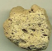
Fig.3 Pumice
1.1 Remediation of a pipeline system using LDG
LDG is commonly used for ground fill applications in which a lightweight fill material is needed to reduce stress on underlying structures.Pumice is a volcanic rock that is highly vesicular and rough in texture,with a relatively low density of about 640 kg/m3(about 25%the density of sand).Pumice is widely used in industry,especially to produce lightweight concrete or insulative low-density cinder blocks.Pumice is easy to work with during ground fill construction.It is durable and has no negative environmental effects.Other positive features of pumice include fire safety and cost-effectiveness.
The remediation scheme was primarily intended to decrease overburden pressure and soil structure interaction force.It required replacing the soil backfill with low-density pumice.To provide full remediation,pumice was placed on top of and beside the pipeline that passed through the site of the fault.
2 Centrifuge Modeling
The details of the centrifuge tests that were done to observe the behavior of a buried pipeline under reverse faulting are shown in Table 1.All Ng or centrifuge tests were designed at 40 g and simulated at a maximum 2.3 m fault offset.The deformation angle of the fault was 60°and the fault angle of the pipe was 90° for all tests.The diameter of pipes was 8 mm,which corresponded to 0.32 m in the prototype.For all tests,a diameter-tothickness ratio of 20 was chosen.The ratio of burial depth to the diameter of the pipe was 2.8 in Test 1 and 6 in Tests 2 and 3.The relationship between the parameters in the model and the prototype are summarized in Table 2.
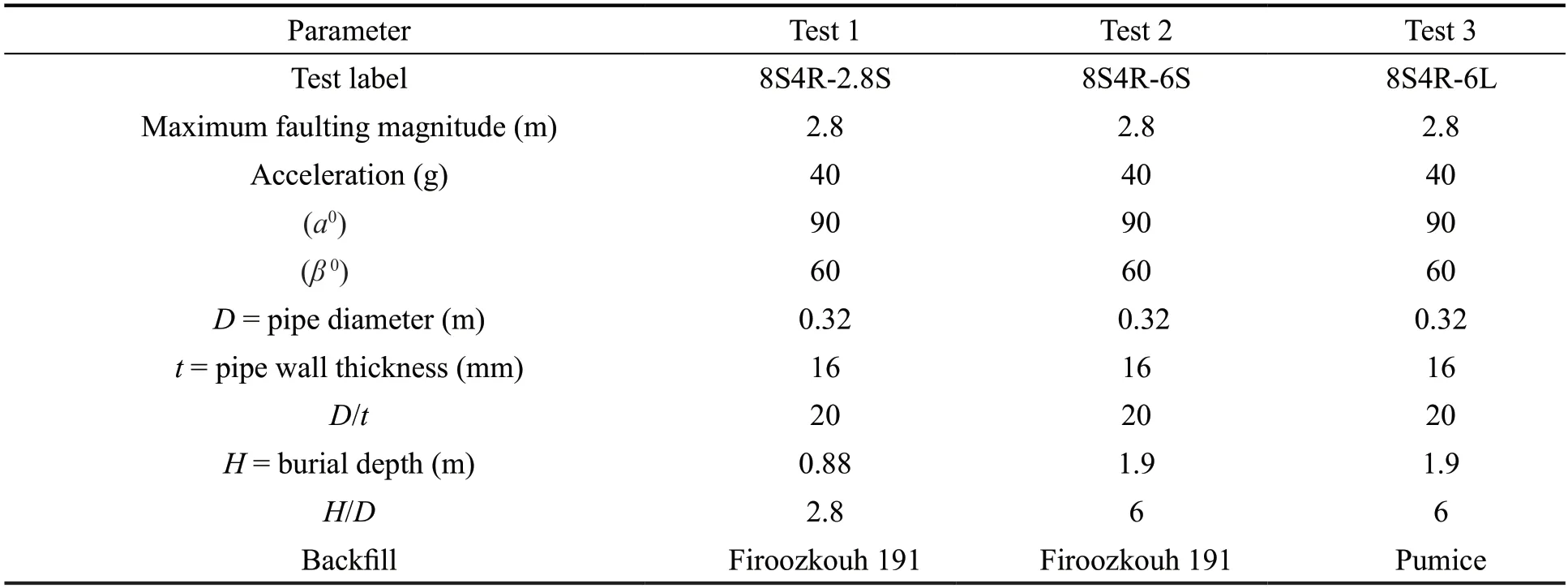
Table 1 Details of centrifuge model tests (dimensions in prototype scale)
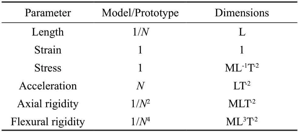
Table 2 Similitude rules of centrifuge model tests
2.1 Faulting simulator
FSUT-RN 60.8,the simulator used at the University of Tehran,is made of aluminum alloy and weighs 2300 N.The components of FSUT-RN 60.8 are displayed in Fig.4.The outer dimensions include a length of 102 cm,a width of 76 cm,and a height of 68 cm.The soil container is 96 cm long,70 cm wide and 23 cm high (Fig.5).The dip angle of the fault in the simulator is set to 60°(β=60°).The faulting plane divided the container into two uneven halves.The larger half is designed to be movable,and the smaller half is fixed in place.The limit of fault offset of the FSUT-RN 60.8 is set to ±4 cm in themodel,which results in a ±1.6 m fault offset at 40 g in the prototype.
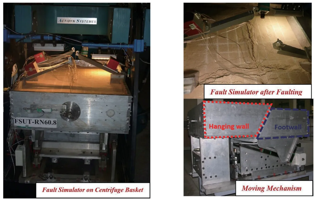
Fig.4 FSUT-RN 60.8 fault simulator parts
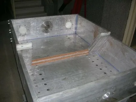
Fig.5 Split container
To boost stability,strength,and rigidity of the moving part and enhance the precision and resistance against unbalanced forces during the faulting procedure,the wedge mechanism was used for moving half.A hydraulic actuator with a 50 kN capacity provided the necessary driving force.This hydraulic jack moves the wedge element of the mechanism in and out under the movable half.The sliding rate of fault is close to 30 cm/s on the prototype scale.
2.2 Soil properties
Table 3 shows the properties of the Firoozkouh 191 sand used in this study.The Toyoura sand′s properties are also shown in Table 3 for comparison.Figure 6 illustrates the Grain size distribution of soil and trench backfill material.The LDG has an average particle size of 1.4 mm and the coefficients of uniformity and curvature are 1.9 and 1.2,respectively.
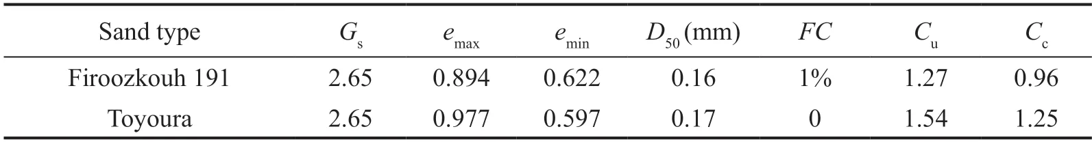
Table 3 Properties of Firoozkouh 191 and Toyoura sand*
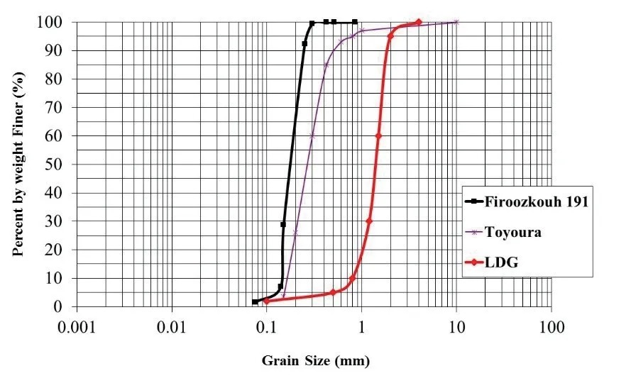
Fig.6 Grain size distribution of soil and trench backfill material
In centrifuge modeling,the soil particle size is important for the study of soil-structure interaction.In this type of modeling,the prototype dimensions are scaled by gravity scaling factorN.However,the scaling down of soil particles by the same factor is impossible because soil behavior will be changed,for example,from non-cohesive to cohesive.To account for the effects of soil particle size scale,some criteria have been recommended,such as those proposed by TC2.
According to the recommendation of TC2 based on centrifuge test data obtained from Ovesen (1981) and Dickin and Leuoy (1983),the smallest ratio of pipe diameter to average soil grain size (D/D50) must be at least 48.The average grain size (D50) of Firoozkouh 191 sand was 0.16 mm and (D/D50) was 50,which satisfied the criterion.
The D50 of LDG in a centrifuge model was 1.4 mm,which represents the LDG grain diameter of about 50-60 mm in prototype at a g level of 40.In other words,the LDG material grain size is completely to scale.It should be mentioned that the natural Pumice is mined,crushed,and graded in plants,therefore,the desired size of Pumice grains can easily be designed and produced to be used in the prototype.
2.3 Model ground preparation
Moist soil (4.5% to 5% moisture content) was placed inside a soil container in layers 4 cm thick and was then compressed using a compactor.The input energy,provided by 10 drops from a height of 10 cm,was~425 J/m2,and a relative density of~85% was achieved.A trench was then excavated in a soil container filled with compacted soil.A pipe was placed into the trench,and either the extracted soil or LDG (pumice) was piled over the pipe.
The LDG backfill in the model was composed of finegraded pumice utilized to model the larger pumice that filled the pipeline trench in the prototype.The specific weight of the pumice was estimated to be less than the specific weight of the Firoozkouh 191 sand compacted around the pipe.Figure 7 shows the plan view and a cross-section of the pipeline and modified trench with LDG.
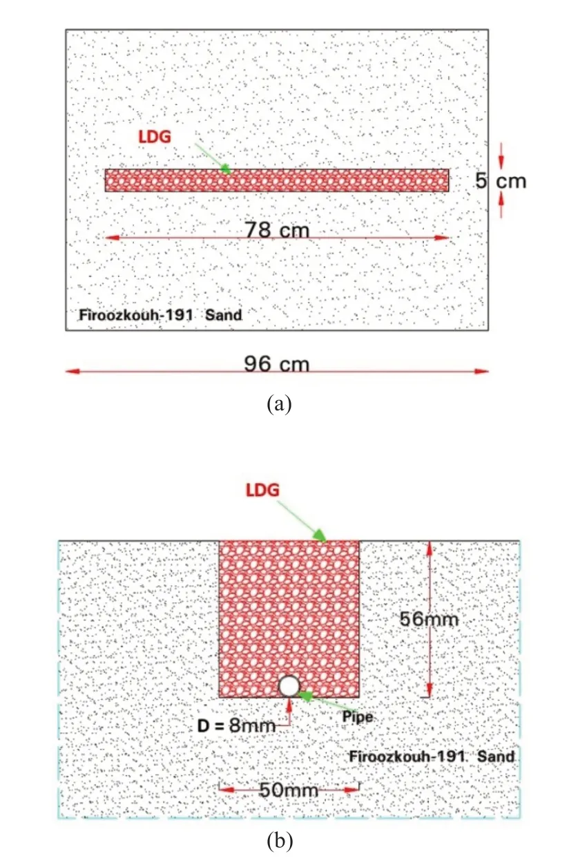
Fig.7 LDG in a pipeline trench: (a) plan view;(b) cross-section
2.4 Pipe specifications
Table 1 provides the model specifications.The pipes in all tests were manufactured using stainless steel 316 that fulfilled the specification with ASTM A999/A999M.All tests were conducted on a pipe-fault angle of 90°.As demonstrated by Fig.8,fixed connections were used to connect the pipeline to the end walls of the simulator.Oxyacetylene gas was used to weld the pipe to a bolted rod at both ends,and nuts were used to fasten the end of these bolted rods to the ends of the simulator.
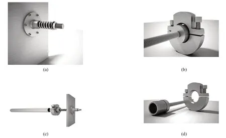
Fig.8 The connection of the end of the pipe to the fault simulator box
To recreate realistic field conditions and eliminate the impact of pipeline end conditions on pipes’ response,the longitude of the pipeline was modeled to be affected by nothing but faulting.The part of the pipe that was located between the two anchored stations on the halves of the fault,and which was affected,must be simulated.The anchored stations were assumed to be the last points on the pipeline subject to faulting.This part of the pipe and the distance between the two anchored stations was analytically calculated to be 70-80 m based on Newmark and Hall′s (1975) and Kennedyet al.(1977) analytical model for calculation of the anchor point.According to the scaling laws for the Ng simulation at 40 g,a 1 m length modeled pipe would accurately simulate the 40 m prototype pipeline.However,the boundary conditions would affect model response.
The boundary conditions for the modeled pipeline influenced pipe behavior because it is impossible to model the entire length of a pipeline.A semi-rigid pipe support condition that is neither a fully hinged nor a fully fixed joint can be utilized in a case such as this.In such a setup,the pipe is neither free with deformation nor fixed,because the remaining part of the pipeline would prevent free deformation.The simulation of a semi-rigid joint is not possible because the rate of pipeline deformation at the end of the pipe model is unknown.However,realistic pipeline behavior might be realized by considering the limit boundary conditions of fully hinged and fully fixed cases.In this study,fixed conditions were simulated because they would best replicate an actual state;nonetheless,simulating a pipeline with a free condition is required and recommended for future studies.
Steel pipelines are almost always coated to prevent corrosion in actual conditions.Polymer tape was used to cover the pipe model to allow consideration of the friction coefficient between soil and the pipe.This coating decreased the friction between the soil and the pipe.It also protected the strain gauges during the test.
2.5 Instrumentation
Displacement transducers and strain gauges were used to monitor the behavior of the pipeline due to faulting.Six LVDT (displacement transducers) measured model displacement factors,such as fault offset,pipe axial displacement,and vertical displacement of the pipeline profile during faulting (Fig.9).Twenty-six strain gauges were installed in a circumferential and longitudinal direction on the pipe at seven positions along the pipeline.At the position of the pipe where a high strain was expected,a compatible strain gauge with a large strain of up to ±20% was used.All strain gauges were arranged in a quarter bridge configuration to make possible the separation of bending strain from axial strain along the pipeline.The frequency of sampling during the testing procedure was 50 Hz.
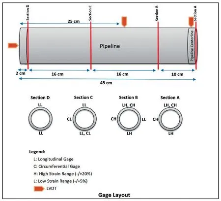
Fig.9 Strain gauges and displacement transducers layout along the pipe
Because of the need to monitor any deformation or displacement in the depth of the model,colored sand layers were used for marking purposes.Also,a network of colored markers was created on the surface of the model to delineate surface deformation.
3 Experimental results and discussion
3.1 Effects of the remediation method on ground and pipe deformation
Considerable deformations occurred along the pipe and on the soil′s surface during all three tests (Fig.10).As shown,in Test 2 the soil surface was not disturbed,but in the other tests the pipe emerged from the soil.Different soil surface deformations and longitudinal cracking could be discerned in a zone above and parallel to the pipe.Similar soil surface deformations were observed in a fault zone,and parallel cracks to the fault on the soil surface resulted from similarity of faulting conditions.
The pipe buckled and was exposed at the soil surface when it was buried at a shallow depth,i.e.,whenH/Dwas low (Figs.10(a),11(a) and 12(a)).Also,the deformation mechanism might be affected by variations in pipe diameter and relative stiffness (D/t) (Rojhaniet al.,2012a).According to the Rojhaniet al.(2012b) results,the pipe deformed in a beam buckling mechanism,such as that seen in Fig.10(a),was caused by the lowD/tratio.Larger pipe diameters and stiffness resulted in local buckling or wrinkling.
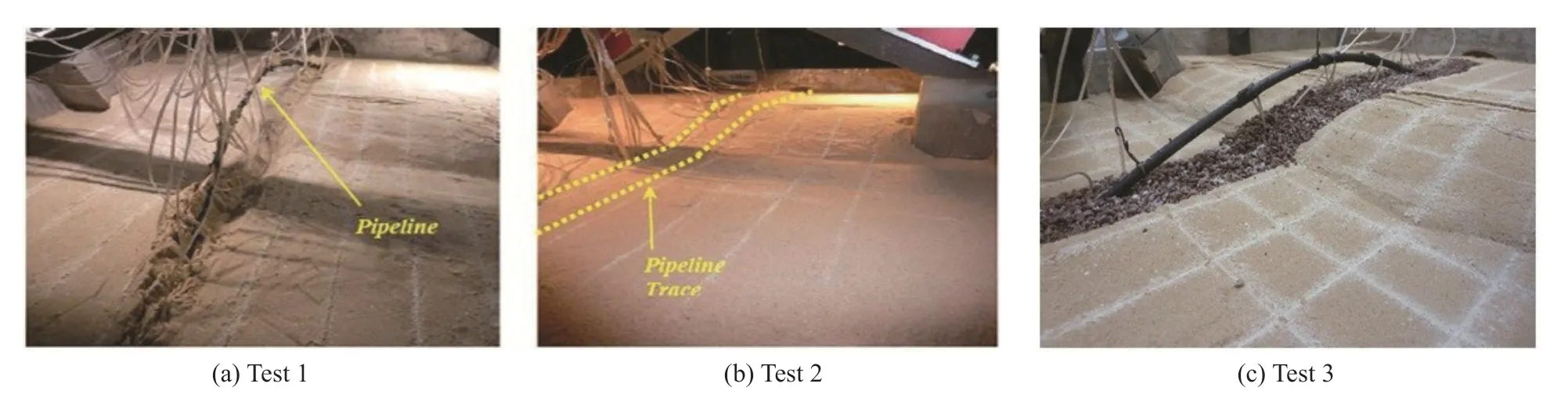
Fig.10 Post-test surface observation
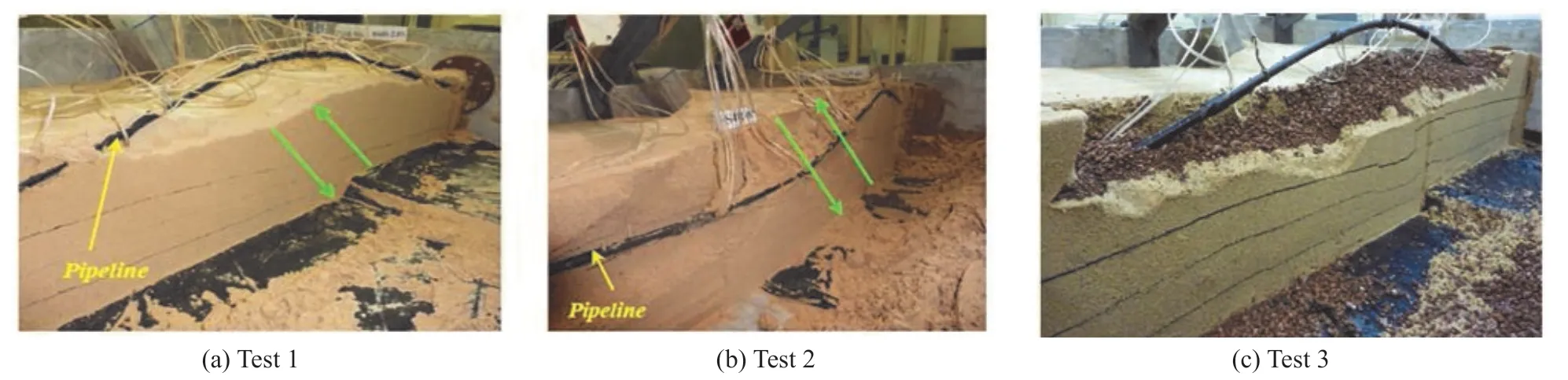
Fig.11 Pipe and soil section deformation-after faulting (left view)
Circumferential cracking of the pipe and leakage may occur in the pipe wall at the wrinkling point.Beam buckling deformation is more desirable to maintain pipeline performance because of the lower potential for tearing in the pipe wall.Moreover,the deformation curve is nearly symmetric for this form of deformation.
A change in burial depth also produced deformation mechanisms.Increasing the burial depth led to an increase in soil stiffness and prevented pipe eruption from the soil.Test 2 resembled Test 1,with an increase in burial depth,and resulted in deformation of the pipe into an unfolded S-shape under the soil surface(Figs.10(b),11(b) and 12(b)).Bending was focused on two points,one on the footwall wall side and another on the hanging side.Along the footwall side,the pipe moved downward in response to concentrated bending.Along the hanging wall,the pipe moved upward toward the surface and sometimes broke through.Because of the difference in soil stiffness under the pipe and above of pipe,the amount of downward movement along the footwall was smaller than the upward movement along the hanging wall.
Test 3 repeated Test 2,using different overburden material,and beam buckling was the governing mechanism (Figs.10(c),11(c) and 12(c)).The portion of the pipe that was thrust above the surface demonstrated greater upward movement than the pipes with sand backfills.This behavior was the result of the lower weight of the overburden,which facilitated upward movement of the pipe despite the relatively high burial depth andH/Dratio.Lighter backfill material decreased passive soil resistance and prevented bending concentration,which facilitated the pipe buckling deformation.
Meyersohn (1991) determined the critical cover depth required to transform local buckling into beam buckling in the pipeline,which is a more suitable deformation mechanism (Fig.13).Critical cover depth was determined from the vertical axis using thet/Dratio of the pipe and soil compaction.The degree of backfill compaction is denoted in the figure by the shading.In these tests,local buckling did not occur because of the low relative stiffness (D/t) of the pipes.
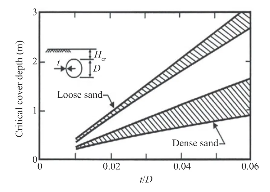
Fig.13 The critical cover depth of the pipe (Meyersohn,1991;O′Rourke and Liu,1999)
3.2 Effects of the remediation method on vertical displacement of pipe
The vertical displacement of the pipelines during faulting is demonstrated in Fig.14.Three sensors located at 8 m on the prototype scale on both sides of the fault and the middle of the pipe were used to gauge displacement.In Test 1,the pipe was quickly exposed at the soil surface because it was buried at a shallow depth.When fault offset had exceeded 1.3 m,beam buckling deformation caused vertical displacement to reach a plateau.In Test 2,the pipe formed an unfolded S-shape and experienced insignificant displacement along the footwall side and slight deformation.
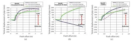
Fig.14 Vertical displacement along pipe: (a) Test 1;(b) Test 2;(c) Test 3
In Test 3,the pipe was backfilled with LDG and was not at a shallow depth.Displacement differed from that of Test 2 and was similar to the displacement recorded for Test 1.The pipe,because of beam buckling deformation and vertical displacement,was exposed at the soil surface.Displacement increased by about 30% compared to Test 1.This appears to have occurred because sand was replaced with LDG.
3.3 Effects of the remediation method on axial strain
Figure 15 shows the variation in axial strain along the pipeline during testing.For the prototype scale,the maximum offset during testing was 2.3 m.No extensive axial strain was observed in the tests,and the pipe bending was predominant during faulting.As the faulting began,axial strain reached about 0.15% and became constant.While the fault sliding increased and pipe buckling was initiated,the value of axial strain dropped to about zero.In Test 2,when the pipeline deformed into an unfolded S-shape,axial strain showed a slight change at the highest curvature point of the pipe.This change may have been larger at this point,but since no strain gauge was available at the highest curvature point,it was not precisely recorded.
A comparison of the tests results shows that,for a givenD/tratio,the onset of pipe deformation was delayed by increasing burial depth.For the LDG backfill with the sameD/t,no delay was observed at the onset of axial deformation of the pipe,despite the great depth.The use of LDG as overburden produced an axial strain similar to that of the pipe at a shallow depth.
Figure 16 depicts the peak axial strain versus fault offset.It can be observed that increasing burial depth increased axial strain.It also can be seen that the strain gradient increased because of deeper embedment and the peak axial strain occurred at a larger offset.The strain gradient was greatest for the LDG overburden,and the peak axial strain value fell between the values for the other tests.
A similar remediation method was investigated by Chooet al.(2007) in which EPS geofoam blocks were used as low-density backfill.They reported that such material decreased the axial strain of about 17% to 30%.It should be noted that these results were summarized based on a series of centrifuge model tests for strike-slip faulting.
3.4 Effects of the remediation method on bending strain
Figure 17 shows the convex and double curvature bending strain curves along the pipe.The double-arc was convex on one part of the fault and concave on the other.The bending strain curve was convex when the pipe was displaced upward and vice versa when it was displaced downward.
Figure 17 (a) shows that the bending strain graph along the pipeline underwent a beam buckling mechanism.The bending strain profile was analogous to the pipe deformation curve,with a small irregularity seen on the footwall hand from the sliding angle of the fault plane and the movement direction of the pipe.Along the footwall hand,the pipe emerged from the soil surface.A small fall in the graph along the footwall is the result of bending in the pipe caused by the weight of the overburden as the pipe rose.On the hanging wall side,no changes occurred because the pipe laid on a stiff and homogeneous soil mat.

Fig.15 Axial strain at various offsets versus distance from fault: (a) Test 1;(b) Test 2;(c) Test 3
Figure 17 indicates that the maximum bending strain was 0.8% and occurred in the middle of the pipe in response to beam buckling.Also,at the end of the pipe,a strain of 0.6% was gauged.Meyersohn (1991),Ariman and Lee (1989),Kyriakideset al.(1983),Hobbs (1981),Marek and Daniels (1971) have studied analytical methods for beam buckling deformation.
Figure 17(b) demonstrates the bending strain curve for Test 2.As shown,the bending strain graph along the pipeline with different curvatures and two peaks was asymmetric.Since the hanging wall part of the simulator moved upward relative to the footwall part with the deformation angle of the fault (60°),the pipe moved upward and out of the soil surface along the footwall.Bending in the pipe was caused by movement of the overburden soil in the reverse angle compared to the bending movement in response to faulting.

Fig.16 Peak axial strain versus fault offset
Along the hanging wall side,the effects of faulting and overburden occurred in the same direction;thus,the bending strain was nearly zero on the footwall hand at the boundary of the pipe and reached 1.2% on the hanging wall side.The maximum bending strain occurred on the footwall side about 3 m distance from the fault.Along the hanging wall side,the peak bending strain decreased in response to the pipe moment at the end of the pipe.The unfolded S-shape deformation began at 0.6 m of the faulting offset.The strain curves were located at 0.3 m offset for Tests 1 and 2,but the peak strain for Test 2 was twice that of Test 1.This observation suggests that increasing the burial depth of the pipe accelerates the rate of bending strain.
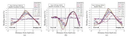
Fig.17 Bending strain at various offsets plotted as a function of distance from a fault: (a) Test 1;(b) Test 2;(c) Test 3
Figure 17 (c) indicates that the results for Test 3 were similar to those for Test 1.Although the burial depth was the same for Tests 2 and 3,the bending strain curves were different since the remediated pipe experienced beam-type buckling.When the remediation method (i.e.,LDG backfill) was used,the deformation concentration decreased,and a bending strain of >1%at the strain concentration points decreased to <1%(~15% reduction).In addition,the location of the peak strain moved to the center of the pipe.Also,the bending strain decreased by about 40% at the ends of the pipe.Unlike Test 1,the bending strain in the middle of the pipe showed an increase of about 25% and was similar at the ends of the pipe.
Figure 18 demonstrates the variation of peak bending strain during faulting.In the first Test,the bending strain was slight prior to the beginning of buckling;however,at the start of buckling,the peak bending strain at the center of the pipeline and for an offset of 2.3 m rose to more than 0.8%.In the second Test on the footwall side and for an offset of 2.3 m,the maximum bending strain increased in an approximately linear gradient,to 1.2%.Along the hanging wall hand,after the strain reached 0.6% for an offset of 0.9 m,it remained unchanged.In the third Test,the peak bending strain at the center of the pipeline increased with a higher gradient than in Test 1,to 1% for an offset of 2.3 m.
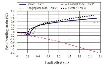
Fig.18 Peak bending strain versus fault offset
Chooet al.(2007) showed that using EPS geofoam blocks as low-density backfill leads to a 45%-60%reduction in the pipe bending strain in contrast to that of the unremediated pipe.
The proposed mitigation in this study also resulted in a considerable decrease in a strain of 15% to 40%.Moreover,changes in the deformation mechanism of the pipe led to efficient damage mitigation.The use of pumice as the backfill material showed advantages over the EPS geofoam blocks,such as better workability during construction,lower negative environmental effects,better resistance when exposed to fire and sunlight,increased durability,and cost-effectiveness.
4 Conclusions
A series of centrifuge experiments were carried out to evaluate the response of continuously buried steel pipelines under reverse faulting.A remediation technique using LDG backfill for buried pipelines under PGD was studied.A stainless-steel pipe was tested at two depths,and the effect of pumice backfill material was examined.The pipes were connected to a soil container by a fixed joint for all tests,and the faulting angle was 60°.Vertical displacement,bending strain and axial strain of the pipe during faulting were recorded using several strain gauges and displacement transducers.
Varying the burial depth of the pipe considerably changed the pipe deformation mechanism.The type of deformation mechanism in the shallower burial depth was beam buckling,which is preferable to wrinkling or local buckling because the pipeline will be more likely to remain in service under such circumstances.Deeply embedded pipe was subject to an unfolded S-shape deformation that significantly damaged the pipeline.Increasing the burial depth of the pipe changed the response of it from beam buckling deformation mechanism to unfolded S-shape.None of the pipes experienced wrinkling because they had low section slenderness ratios (D/t).This behavior is accordant with the Meyersohn graph (1991) for critical burial depth.Peak axial strain raised as burial depth increased.
The use of LDG to fill the pipeline trench was an efficient technique that improved pipeline response to faulting.LDG backfill played a significant role in pipe deformation type because it changed the deformation mechanism to beam buckling.In contrast to wrinkling or other types of damage,the better performance made it safer,and it experienced less damage.Circumferential cracking of the pipe wall and leakage was prevented,which,in a pipeline carrying flammable materials like gas,could pose a serious risk of explosion and significant damage.Pipes experiencing beam buckling deformation were subject to complete bending;thus,no considerable axial strain was observed.
The use of LDG (pumice) backfill instead of soil decreased the overburden pressure and the soil-pipe interaction forces acting on the pipelines and consequently improved the pipe deformation mechanism to a more desirable type.Pumice is more suitable than the EPS geofoam blocks because it offers increased workability during construction,does not pose environmental problems,shows resistance to fire and sunlight,and is durable and cost-effective.
The effects of internal pressure and realistic semirigid supports of pipe on pipeline response were not considered in the present research.A future investigation utilizing a free-end pipeline and the use of pipes experiencing internal pressure also is recommended.The efficiency of the new technique was demonstrated,and it was shown that the behavior of the remediated pipe was better than that of the un-remediated pipe.The influence of the various effective parameters relating to the use of LDG backfill should be studied in more depth.
Notation
Cc=coefficient of curvature
Cu=coefficient of uniformity
D=pipe outer diameter
D50=average particle size of sand backfill
emax=maximum void ratio
emin=minimum void ratio
FC=fine content of soil
Gs=specific gravity of soil particle
H=depth of soil from the surface to the top of pipe
R0=pipe radius
t=pipe wall thickness
α=pipeline fault orientation angle
β=fault deformation (dip) angle
EPS=expanded polystyrene
LDG=low-density gravel
Acknowledgement
This research was carried out at the Physical Modeling and Centrifuge Laboratory of the Soil Mechanics and Foundation Engineering Department in the School of Civil Engineering at the University of Tehran.The assistance and constructive suggestions of all experts and personnel of the lab,especially Mr.Ebrahimi,Mr.Jabarzadeh and Mr.Pirnazari,are greatly appreciated.
杂志排行
Earthquake Engineering and Engineering Vibration的其它文章
- Seismic response of selective pallet racks isolated with friction pendulum bearing system
- Reliability and sensitivity analysis of wedge stability in the abutments of an arch dam using artificial neural network
- Study on time-varying seismic vulnerability and analysis of ECC-RC composite piers using high strength reinforcement bars in offshore environment
- Optimization of design parameters for controlled rocking steel braced dual-frames
- Effects of timber infill walls on the seismic behavior of traditional Chinese timber frames
- Steel rings as seismic fuses for enhancing ductility of cross braced frames