Optimization of design parameters for controlled rocking steel braced dual-frames
2022-10-19SobhanGhasemiFirooziNezamabadiAbdolrezaMoghadamandMahmoodHosseini
Sobhan Ghasemi,M.Firoozi Nezamabadi ,Abdolreza S.Moghadam and Mahmood Hosseini
1. Department of Civil Engineering,South Tehran Branch,Islamic Azad University,Tehran,Iran
2.Structural Engineering Research Center,International Institute of Earthquake Engineering and Seismology (IIEES),Tehran,Iran
Abstract: A controlled rocking concentrically steel braced frame (CR-CSBF) is introduced as an alternative to conventional methods to prevent major structural damage during large earthquakes.It is equipped with elastic post-tensioned (PT) cables and replaceable devices or fuses to provide overturning resistance and dissipate energy,respectively.Although CR-CSBFs are not officially legalized in globally valid codes for new buildings,it is expected to be presented in them in the near future.The main goal of this study is to determine the optimal design parameters consist of the yield strength and modulus of elasticity of the fuse,the initial force of the PT cable,and the gravity load on the rocking column,considering different heights of the frame,spanning ratios and ground motion types for dual-configuration CR-CSBF.Nonlinear time-history analyses are performed in OpenSees.This study aims to define the optimal input variables as effective design parameters of CR-CSBFs by comparing four seismic responses consisting of story drift,roof displacement,roof acceleration and base shear,and also using the Euclidean metric optimization method.Despite the previous research,this study is innovative and first of its kind.The results demonstrate that the optimal design parameters are variable for various conditions.
Keywords: self-centering rocking steel braced frame;design parameters;optimization;low damage
1 Introduction
Conventional buildings must be designed to make sure of modern seismic design codes (ASCE-7,2016;IBC,2018) for life safety and collapse prevention.It is possible by ensuring the strength and ductility of the structural members.In the last two decades,lateral resisting systems have been generated based on low damage approach treated as rocking controlled steel braced frame (Iwashitaet al.,2002;Wiebe and Christopoulos,2015),concrete rocking wall frame(Ajrabet al.,2004;Grigorian and Grigorian,2015a and 2015b),self-centering timber system (Buchananet al.,2008;Francescoet al.,2015),wooden coupled wall (Smithet al.,2007),self-centering concrete frame(Zhang and Hu,2010),confined-masonry rocking wall(Toranzoet al.,2009),foundation rocking and uplifting(Kanmohammadi and Mohsenzadeh,2018);rocking moment frames (Tahmasebiet al.,2014;Moradiet al.,2015) and infilled rocking wall frame (Panet al.,2018).The novel systems cause to enhance seismic performance and reduce casualties in the structure.Rocking motion was first presented by Housner (1963).Later,Clough and Huckelbridge (1977) and also Kelly and Tsztoo(1977) further investigated this type of structural behavior,and more recently,several other types have been assessed and approved (e.g.,Pollino and Bruneau,2010;Wiebeet al.,2013a;Hosseiniet al.,2016).In the other experimental studies,such as Rokeet al.(2008),Eatherton and Hajjar (2010),Sauseet al.(2010),Maet al.(2010b),Wiebeet al.(2013b),and Eathertonet al.(2014) the useful effects of controlled rocking steel braced frame in reduction post-earthquake damage are evaluated.Furthermore,analytical studies have been performed by Sauseet al.(2006) and Maet al.(2010a)to assess the capability of controlled rocking steel braced frame.In a controlled rocking steel braced frame,the column is allowed to uplift from its foundation during an earthquake,in which the frame remains elastic.
There are various configurations for self-centering rocking controlled frame by considering different types of post-tensioning cable and fuse position.In some studies,the single-configuration controlled rocking frame has been evaluated (e.g.,Maet al.,2011;Lathamet al.,2013).Dual-configuration of the controlled rocking steel braced frame was developed by researchers earlier (e.g.,Eathertonet al.,2008;Rahgozaret al.,2016;Rahgozar and Rahgozar,2020;Ghasemiet al.,2021).This paper is focused on the behavior of dual-configuration,controlled rocking concentrically steel braced frame(CR-CSBF) equipped with post-tensioned (PT) strands and shear energy-dissipative devices or fuses.In a dual-configuration CR-CSBF,post-tensioning cables have been incorporated in the center of each rocking frame,and two adjacent frames have been connected by energy-dissipative devices or fuses,which are placed in the middle of the height of each story (Fig.1).The aim of this study is to achieve the optimal design parameters,including the yield strength (σyf) and modulus of elasticity of the fuse (Ef),the initial force of the PT cable(FPT),and the gravity load on the rocking column (PD) by using a multi-objective optimization method on seismic response consist of peak story drift (PSD),peak roof displacement (PRD),peak roof acceleration (PRA) and peak base shear (PBS).Design parameters are deemed as input variables and are also used in the factor combination in this paper.Additionally,five relative-span ratios orA/B(Ais frame length andBis the length between two adjacent frames) and two types of ground motion,including farand near-field pulse subset at the maximum considered earthquake (MCE) level are considered.Three different heights are also considered for the frame,which are 3-,6-and 9-story.Computational models are developed for CRCSBFs to access this goal.Figure 2 shows the idealized not-to-scale behavior of the self-centering system,fuse and PT cable.Figure 2(a) is the sum of Fig.2(b) and Fig.2(c).The following sections describe the research process.
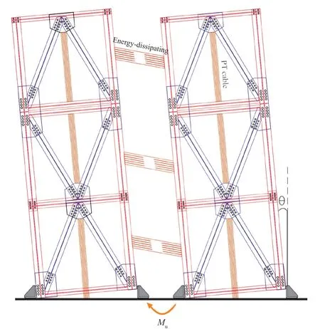
Fig.1 Dual-configuration of CR-CSBF

Fig.2 Flag-shaped hysteretic curve (not to scale) of (a) CR-CSBF,push and hysteretic curves of (b) fuse,(c) PT elements
2 Analytical model attributes
2.1 Studied prototypes
A set of considerations such as various spanning ratios (A/B),number of stories and ground motion categories are chosen to evaluate the dual-configuration controlled rocking concentrically steel braced frame.Figure 3 illustrates the typical prototypes of the CRCSBF.In this study,five amounts are considered for spanning ratio (A/B=1.5,2.0,2.5,3.0 and 3.5),and three-,six-and nine-story are also considered for the elevation of dual-configuration CR-CSBF.In general,30 analysis cases with differentA/B,frame height and ground motion are generated,as summarized in Table 1.Each analysis case is defined by the abbreviationXYZ,whereXis the number of stories (3,6 and 9),Yis the type of ground motion (“f” conforms with far-field and“n” conforms with near-field pulse-like),andZis the spanning ratio (A/B) of controlled rocking steel braced dual-frame.Thus,the expression 3f1.5 (the first analysis case in Table 1) infers that it is related to the three-story frame case with a relative-span ratio of 1.5 analyzed at the far-field ground motion.The prototypes are assumed to be located in Los Angeles,California,and designed for site class D.The entire length of the dual-configuration CR-CSBF (2A+B) and the story height are also assumed 9 m and 4 m for all samples,respectively.The crosssectional area of each post-tensioning cable (APT) for three-,six-and nine-story CR-CSBF is also derived 20,30 and 75 cm2,respectively.As argued later,the initial force of post-tensioning cable (FPT) is considered as an input variable in this paper.
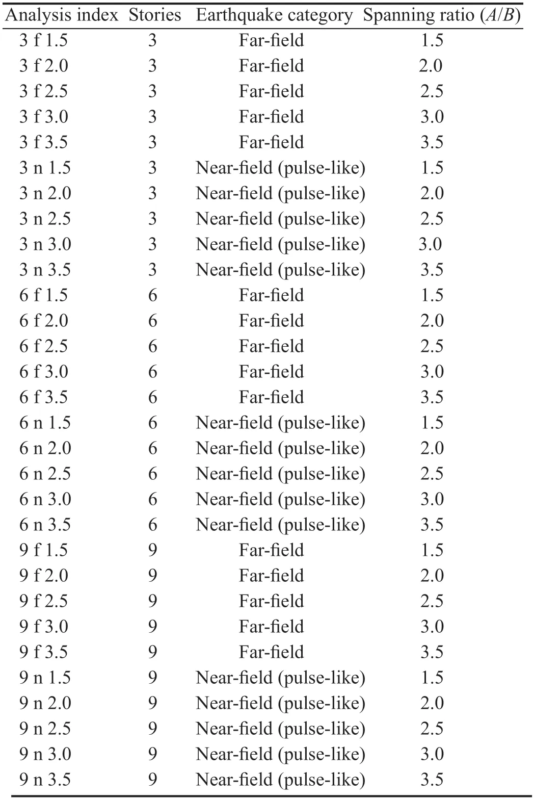
Table 1 Analysis cases
2.2 Computational modeling
This study prepared a two-dimensional computational model to assess the CR-CSBF system using OpenSees(ver.2.4.6,2015).The frame section sizing results are listed in Table 2,which are determined from the capacity design approach.All of these members,including beams,columns and braces,are modeled as dispBeamColumn element and remain elastic during rocking motion and uplifting.Also,fiber section element is used for the members with four integration points and nonlinear steel02 material with modulus of elasticity of 200 GPa.A damping ratio of 2.5% is applied in the models using Rayleigh damping.

Table 2 Beam,column and brace sections of CR-CSBF used in this study
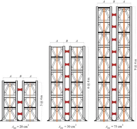
Fig.3 Configuration of CR-CSBF used in this study
Two leaning columns with no lateral stiffness on each side of the rocking steel concentrically braced frame are placed for simulating P-Δ effects arising from the gravity frame,which are connected to the rocking concentrically braced frame using pin ended strut elements.A gap element is used at the base of each rocking column with zeroLength element,which is stiff in compression(MN/mm) without tensile stiffness during column uplift.As can be observed in Fig.4,a detailed scheme of the computational model is depicted.
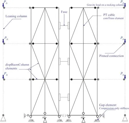
Fig.4 OpenSees model of a three-story dual configuration CR-CSBF
Energy-dissipating devices or fuses are modeled with fiber section and rotational spring at each end to explicitly simulate the flexural,axial and lateral-torsional buckling behaviors of fuses (Eatherton and Hajjar,2010).Hysteretic material is also used to simulate fuses by zeroLength rotational springs.The fiber element with steel01 material is used to capture their hysteretic tension and flexural behavior.
In this study,post-tensioning cables are modeled using a corotTruss element with a series combination of elastic-perfectly plastic and hysteretic material.PT strands only react to tension against the overturning moment.
2.3 Ground motions set
To perform nonlinear time-history analysis (NTHA),22 horizontal components from 12 earthquake events were adapted from FEMA P695 (FEMA,2009).As mentioned earlier,the prototypes are considered to be located in Los Angeles,California,and site class D is assumed.In FEMA P695,the record set is identified based on ground motion characteristics.The selected ground motions set are listed in Table 3.As can be observed,ground motions set consist of two types,far-and nearfield pulse-like.The records set are scaled base on the amplitude scaling method in ASCE-7-16 for maximum considered earthquake (MCE) level.Figure 5 also shows the spectral acceleration of the unscaled far-and nearfield pulse-like ground motion set,separately.
3 Research process
3.1 Sensitivity study and seismic multiple-response
In a rocking steel braced frame,four design variables,includingFPT,PD,σyfandEf,have been determined as effective parameters in seismic response demands(Moradi and Burton,2018).It also is important to specify the high and low levels of them in this system.The high and low values are derived by an algorithm in OpenSees for all frame configurations.Only the low value for the gravity load on a rocking column per floor (2 kN) in the algorithm is assumed to be constant,where the rocking frames does not connect to the gravity frames.These four factors are deemed as influential input variables in this study.
Table 4 summarized the input variables and their level values.On the other hand,four various seismic responses,including PSD,PRD,PRA,and PBS,are obtained in each nonlinear time history analysis (NTHA).In this paper,for evaluating the sensitivity of input factors and their impact on the seismic multiple-response,the factor combinations must be defined.Thus,an effective and appropriate method called design of experiment (DOE)has been used.Design of experiment is the name of an effective and efficient technique for designing processes and predicting their behavioral characteristics in different situations.The term is used when different conditions affect the variables of an issue.Design of experiments allows anyone to gain a better understanding of a process.This solution is actually a well-known method for scientists,specialists and engineers who deal with the methods of improving and developing the studies and products.Considering four input factors and two levels for each of them (see Table 4),24cases are possible.Also,by using the Random Assignment method (Salkind,2010),the selected number of DOEs from the existing factor combinations was considered equal to half of the total factorial design.Therefore,it corresponds to eight various input combinations.
The input (factor) combinations are listed in Table 5.Considering the thirty analysis cases shown in Table 1 and the eight factor combinations listed in Table 5,as well as using the suite of twenty-two ground motions for each model,5280 nonlinear time history analyses are performed in OpenSees in this study.The next section discusses the result of the analyses.
3.2 Description of multi-objective optimization methodology and analysis results
As mentioned earlier,four input variables involvingFPT,PD,σyfandEfare used in the development of eight factor combinations to calculate the seismic response (see Tables 4 and 5).The maximum values of the four seismic responses for each factor combination,each spanning ratio and ground motions set are determined subsequently.
For example,Figs.6(a) to 6(b) illustrate the values of the PSD,PRD,PRA,and PBS of three-story CR-CSBF under near-field pulse-like earthquakes obtained for the first input combinations in Table 5.Given the total number of various inputs,stories,ground motions and responses available,192 diagrams similar to Fig.6 can be drawn.However,this figure is only mentally presented in the process of this research due to the understanding of the relationship between different conditions.

Fig.6 Three-story CR-CSBF response plots of PSD,PRD,PRA and PBS for the first input combination (C1) is subjected near-field pulse-like ground motions
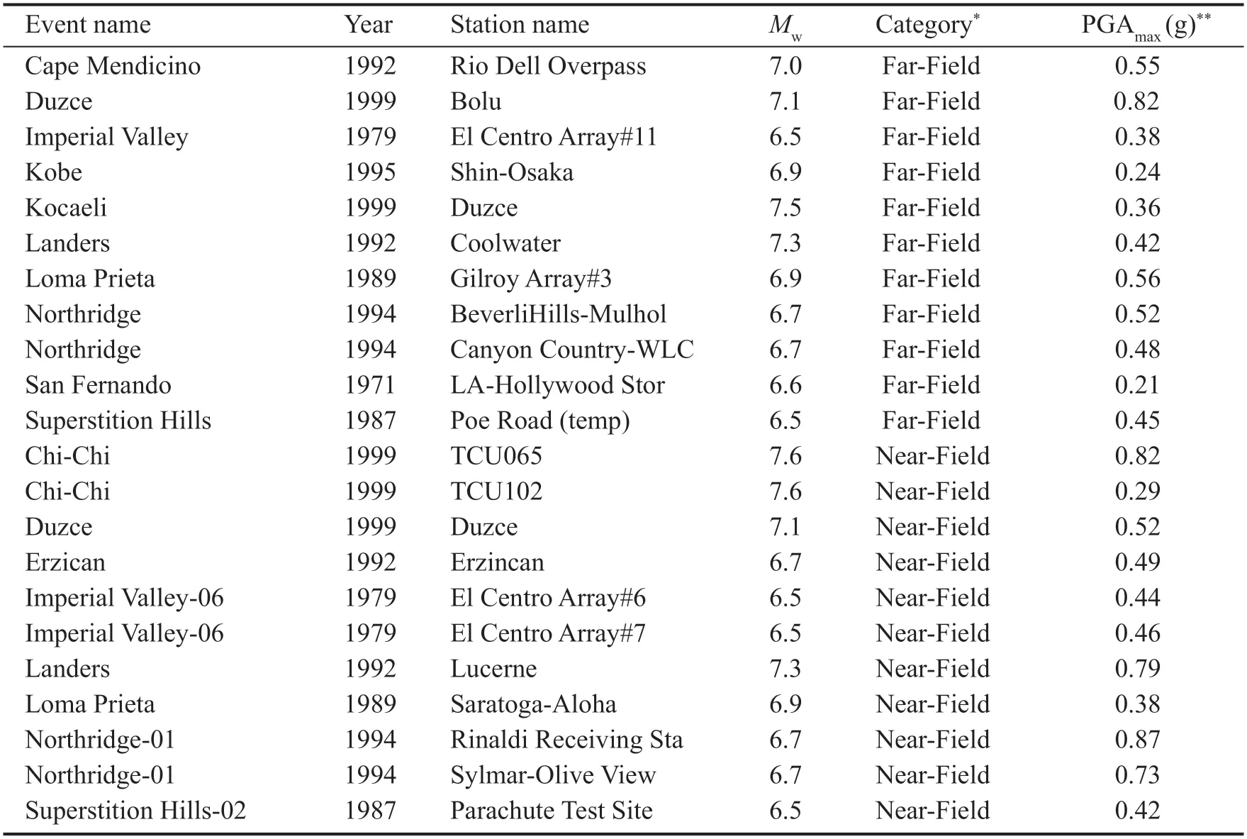
Table 3 Dataset of the ground motion records (FEMA P695)
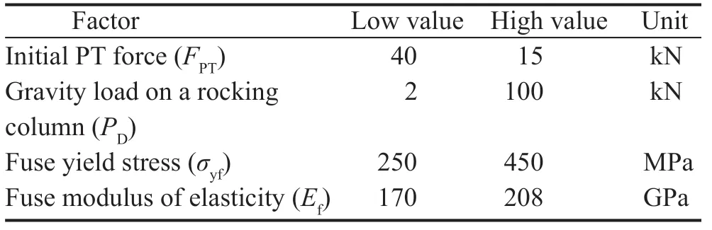
Table 4 Design (input) variables

Table 5 Factor (input) combinations
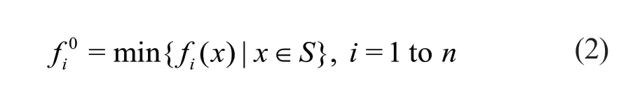
In general,the probability that the optimal values of all the objective functions in the multi-objective optimization problem are at the same point in the design space is very low and rare.In other words,a point in the design space cannot minimize all the objective functions of an optimization problem.Therefore,the ideal (or unique) point will exist only in the criterion space.In addition,it is very difficult to find the ideal points.For this reason,it can be said the ideal points are usually unattainable.In this case,the best option is to find the solutions (Pareto′s optimal solutions),which are closest to the ideal solution in the criterion space.Such a solution is called a compromise solution.The degree of closeness between the ideal point and other points in the criterion space (points that lead to the production of a compromise solution) can be defined by different methods.Usually,the point in the criterion space of a multi-objective optimization problem is known as the compromise solution whose Euclidean distance (dE) from the ideal point is minimal (Deza and Deza,2016).The Euclidean metric (or Pythagorean distance,as-the-crow-flies distance,beeline distance) of a point in the criterion space is calculated from the ideal point through the following equation:

in whichf(x) andf0represent the objective function and a component of the ideal point in the criterion space in a multi-objective optimization problem,respectively.Compromise solutions are also known as optimal Pareto solutions.is calculated by the following equation:
Fig.5 Spectral acceleration of far-field and near-field pulse subset ground motions
ThenandSparameters also indicate the number of objective functions and design space in the multi-objective optimization problem,respectively.
By using this optimization methodology for 40 possible combinations,the optimal condition of design parameters for each of the six final cases,considering eight factor combinations,can be determined (see Table 5).Six final cases are abbreviated by 3f,3np,6f,6np,9f,and 9np in Table A1 and are called three-story rocking steel braced dual-frame is subjected far-field ground motion,three-story rocking steel braced dual-frame is subjected near-field pulse-like ground motion and so on,until the end.
The minimum values of PSD,PRD,PRA and PBS and alsodEof each combination for each final case are presented in “Appendix” (Tables A1,A2,A3,A4,A5,A6),separately.In the tables,the lowest minimum value of PSD,PRD,PRA and PBS is emboldened,the minimum value ofdEfor eachA/Bis shown by using gray highlight and emboldened font and the lowest minimum value ofdEamong all ofA/Bs is emboldened,highlighted and underlined.
4 Conclusions
Self-centering controlled rocking concentrically steel braced frame (CR-CSBF) is a modern low-damage system that can significantly endure a severe earthquake.This novel approach improves steel braced frames′collapse safety incorporating PT cables and replaceable energy dissipative-devices.The study focuses on the assessment of seismic response and optimization of controlled rocking steel braced dual-frames.Four parameters including initial PT force per cable (FPT),rocking column gravity load per floor (PD),fuse yield stress (σyf) and fuse modulus of elasticity (Ef) are assumed as design variables with two upper and lower levels that determined by using an algorithm in eight factor combinations.Four seismic responses,consist of PSD, PRD,PRA,and PBS,are also assessed as the objective functions.Time-history nonlinear analyses are performed in OpenSees on three-,six-and nine-story controlled rocking steel braced dual-frames to investigate design parameters′ impact.For thirty various analysis cases and input combinations,five values of spanning ratio are considered (A/B=1.5,2.0,2.5,3.0,and 3.5).Twenty-two horizontal ground motions are also chosen from FEMA P695 and scaled using the amplitude scaling method based on ASCE-7-16 for maximum considered earthquake (MCE) level into two different categories,including far-field and near-field pulse-like records.In the first place,the obtained results of the four seismic responses are presented and evaluated.Secondly,the study also performed multi-response optimization by the Euclidean optimization method.
The optimization study results demonstrate that for three-story dual-configuration CR-CSBF is subjected to far-field ground motions,the optimal combination for all ofA/Bs is C3or C5.For three-story CR-CSBF is subjected near-field pulse-like ground motions,the optimal combination forA/Bof 1.5,2.0 and 2.5 to 3.5 is C6,C4or C6and C4,respectively.
For six-story CR-CSBF is subjected far-field ground motions,the optimal combination for allA/Bs is C4or C6.For six-story CR-CSBF is subjected near-field pulselike ground motions,the optimal combination forA/Bof 1.5 and 3.5,is C1,andA/Bof 2.0 to 3.0 is C1or C7.
For nine-story CR-CSBF is subjected far-field ground motions,the optimal combination forA/Bof 1.5 to 3.0,and 3.5 is C4or C6and C2or C8,respectively.Finally,for nine-story CR-CSBF is subjected near-field pulse-like ground motions,the optimal combination forA/Bof 1.5 is C1,A/Bof 2.0 and 2.5 is C5,A/Bof 3.0 is C4or C6andA/Bof 3.5 is C2.
In general,it can be concluded that the CRCSBFs are sensitive to various design parameters.The relative-span ratio in controlled rocking steel braced dual-frame was also found to have an effect on the response demands.In spite of the extensive previous study,research seems to be necessary to investigate the optimization of design parameters in controlled rocking steel braced dual-frames.The optimization study results show that fuses with lowerσyfare frequently favorable for attaining optimal conditions of minimized seismic response demands.When the priority is on minimizing PRA demands,Efis only effective in attaining optimal solutions.The most critical factor in reaching the optimal conditions is shown to beFpt.Verification analyses validate and confirm the accuracy of response surface model predictions and optimization results.On the other hand,the relative-span ratio in controlled rocking steel braced dual-frame was also found to have an effect on the response demands.Higher spanning ratios led to higher response demands and the efficacy was greater for the shorter frame models.It can be inferred that the results of the current study were limited to optimizing the design parameters of low-and mid-rise dual-configuration CRCSBF with the shear fuses,which could be presented in the next generation of building codes.As such,future studies are needed on other configurations and fuses.
Appendix
See Tables A1,A2,A3,A4,A5,A6

Table A1 Result of Euclidean optimization for 3f
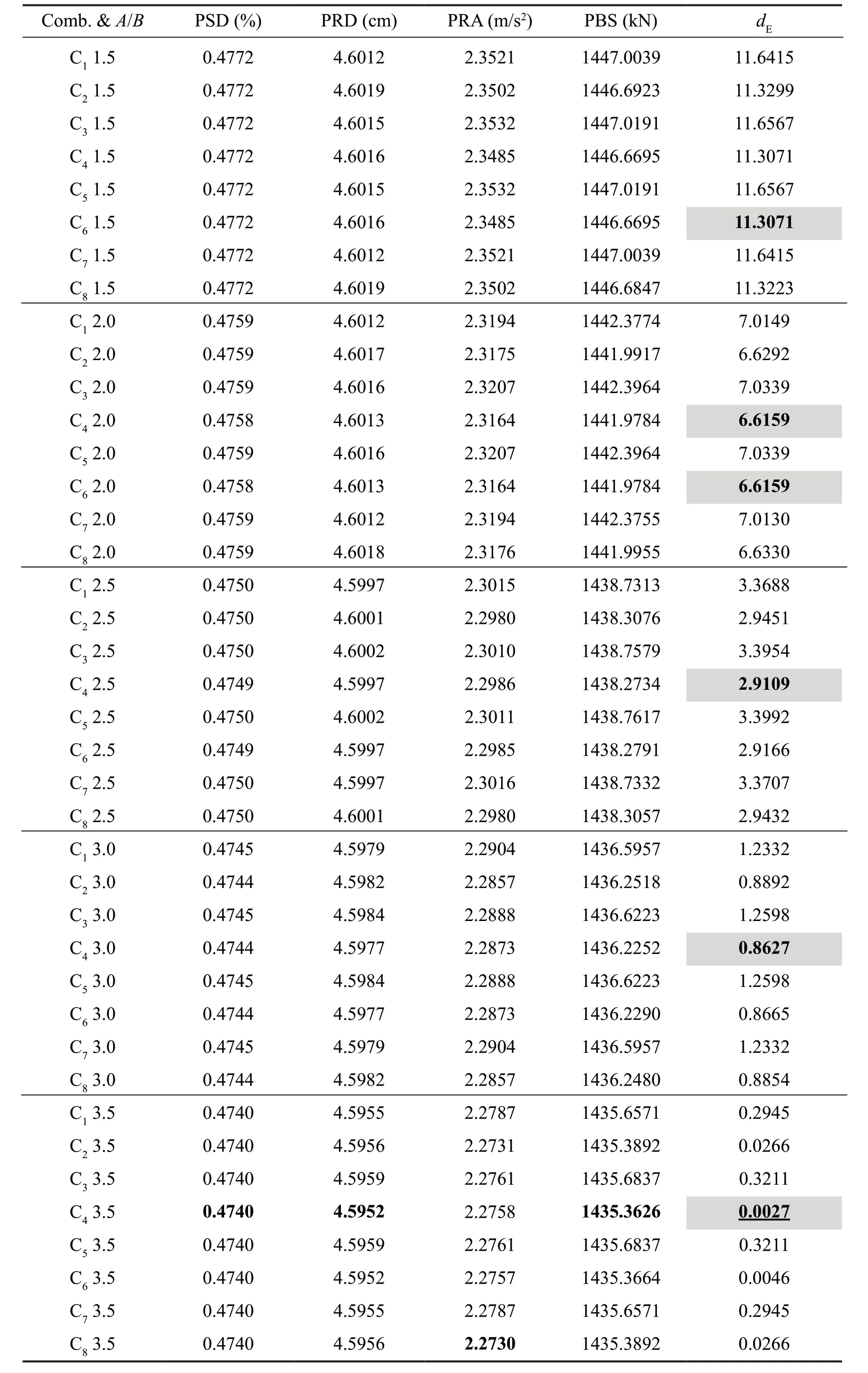
Table A2 Result of Euclidean optimization for 3np
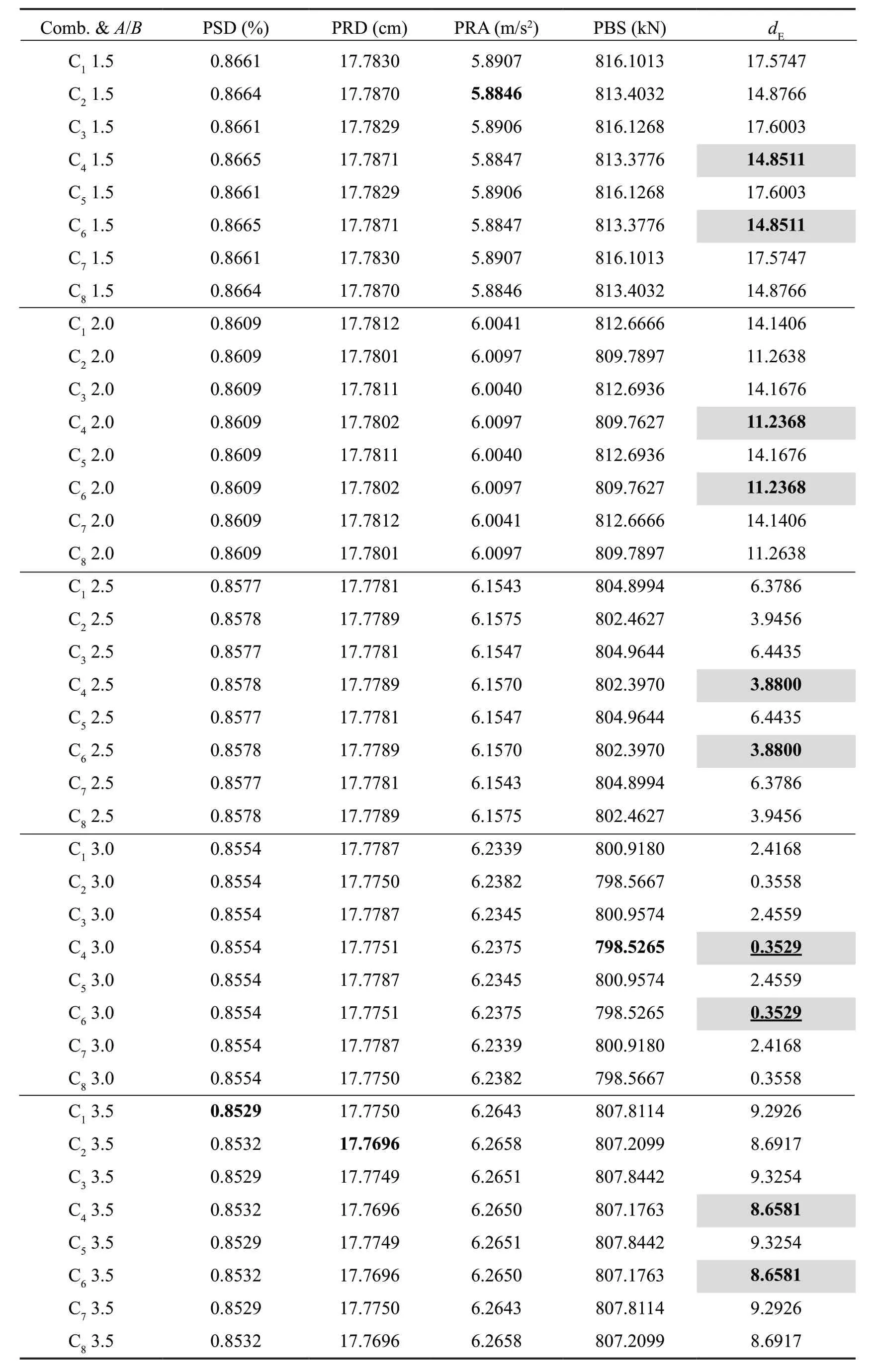
Table A3 Result of Euclidean optimization for 6f
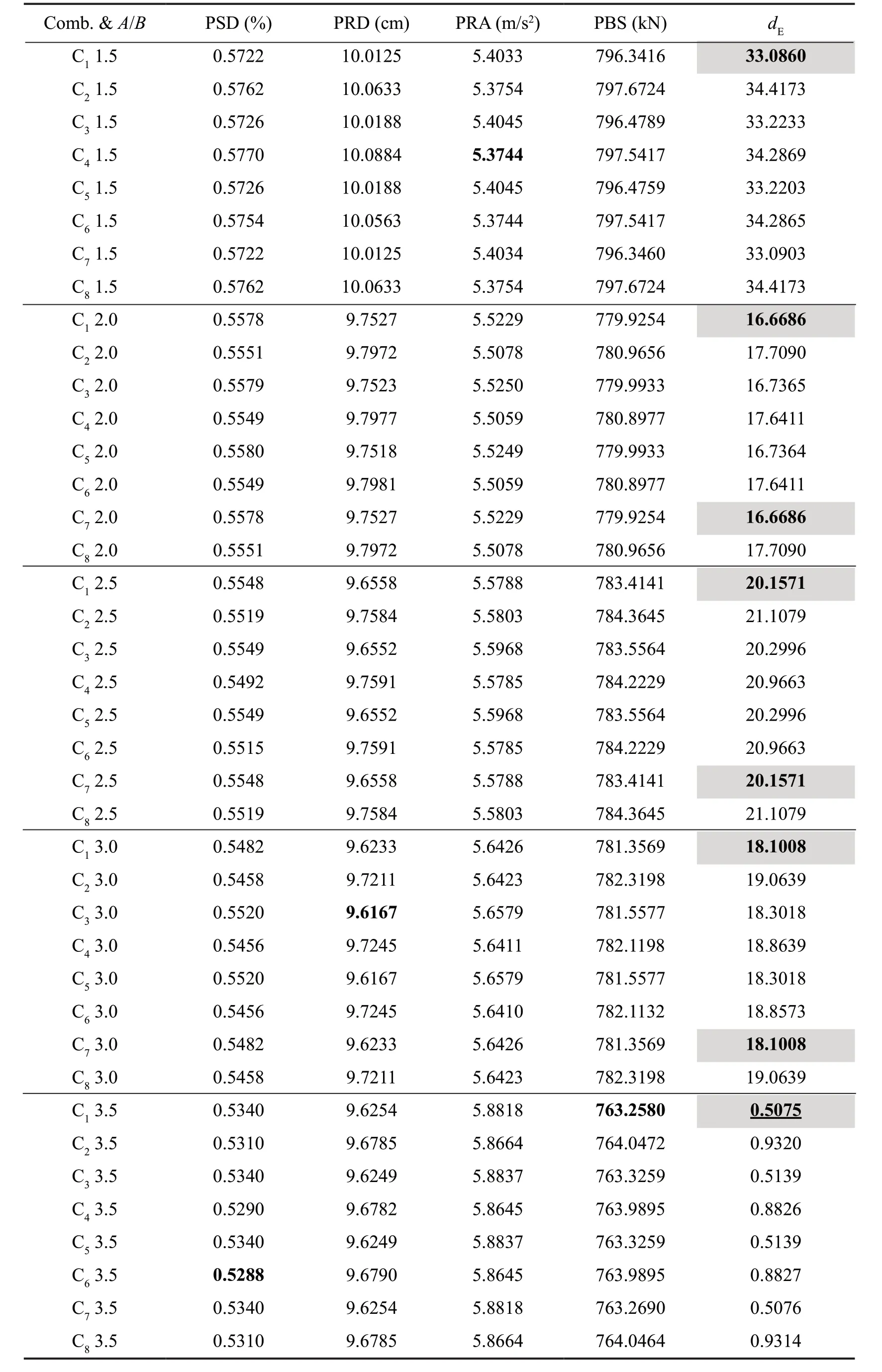
Table A4 Result of Euclidean optimization for 6np

Table A5 Result of Euclidean optimization for 9f
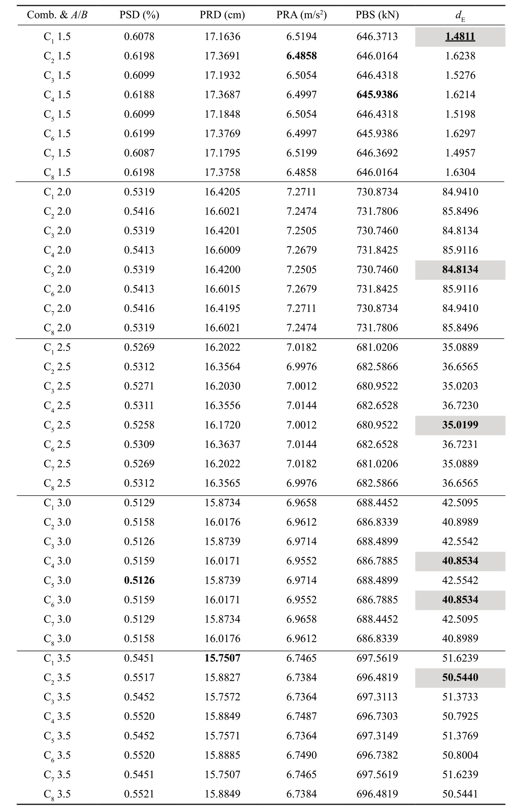
Table A6 Result of Euclidean optimization for 9np
杂志排行

Earthquake Engineering and Engineering Vibration的其它文章
- Innovative mitigation method for buried pipelines crossing faults
- Reliability and sensitivity analysis of wedge stability in the abutments of an arch dam using artificial neural network
- Study on time-varying seismic vulnerability and analysis of ECC-RC composite piers using high strength reinforcement bars in offshore environment
- Seismic response of selective pallet racks isolated with friction pendulum bearing system
- Effects of timber infill walls on the seismic behavior of traditional Chinese timber frames
- Steel rings as seismic fuses for enhancing ductility of cross braced frames