Seismic response of selective pallet racks isolated with friction pendulum bearing system
2022-10-19BennetIpeandSajith
Bennet A.Ipe and Sajith A.S.
Department of Civil Engineering,National Institute of Technology Calicut,Kozhikode 673601,India
Abstract: The concept of base isolation for storage racks is still a developing subject and has not been addressed in the recently updated seismic codes for storage racks.The friction pendulum bearing system (FPS) generates a natural period independent of the structure's seismic mass.This property makes FPS an ideal choice for isolating rack structures since merchandise may be placed on the racks in several possible arrangements.The results of a comprehensive parametric study aimed at evaluating the seismic performance of a four-shelf,two-bay selective pallet rack isolated with FPS is presented in this paper.The influence of radius of curvature of the FPS,seismic mass,and mass irregularity on the rack's seismic response is examined.The effect of variation of the coefficient of friction due to axial loading is studied by choosing friction values from two distinct friction characterization studies.The coefficient of friction calculated from these studies shows mild and significant variations,respectively,for the whole range of static axial loads expected on the isolator,and from different pallet mass arrangements considered.The optimum radius of curvature and the appropriate range of friction coefficient,for the defined range of static axial loads,to attain a desirable seismic performance are determined.
Keywords: selective pallet racks;base isolation;friction pendulum bearing system;cross-aisle direction
1 Introduction
Selective pallet racks have broad applications in industrial warehouses and supermarkets.These skeleton frames support tons of product,much more massive than the self-weight of the structure.The collapse of the racks or the shedding of pallets during an earthquake event is often associated with substantial economic losses and ensuing business disruptions.Moreover,the direct access provided to each bay in a conventional pallet rack system may lead to loss of human life,upon collapses of the rack or product shedding.Furthermore,if a rack collapses on an adjacent rack,it may even lead to a progressive collapse of many racks (Castiglioni,2016).
A classic pallet racking system is shown in Fig.1.Due to the thin-walled nature of uprights,these are prone to local and distortional buckling modes (Diniset al.,2014).Additionally,because these are open monosymmetric sections,they are susceptible to flexuraltorsional buckling (Bernuzziet al.,2015).A braced frame is formed in the cross-aisle direction by bolting or welding diagonal and horizontal bracings of small channel or box sections to uprights spaced apart.Shelfbeams are box,channel or hat sections,with beamend connectors having tabs (Shahet al.,2016).These tabs are hooked onto the perforations on the upright to accommodate pallets of different dimensions.This arrangement forms a semi-rigid frame along the downaisle direction,which is mostly left unbraced to access the pallets at ease.An L-shaped base-plate arrangement is generally used to connect uprights to the floor in such a way that uprights are bolted to the vertical leg of the base-plate assembly and the floor to the horizontal part (Kanyilmazet al.,2016).Steel storage racks are fabricated from thin-walled cold-formed steel sections.The members of a steel storage rack are lightweight due to their smaller thickness,which allows for easy erection and handling.Typical selective pallet racks do not have horizontal cross bracings or diaphragms.Hence,these racks behave as structures with flexible diaphragms(Filiatraultet al.,2008).

Fig.1 General arrangement of a selective pallet rack (see:www.spaceplanners.org/palletized-rack.html)
Many storage racks have collapsed along the crossaisle direction in past earthquakes.In the Northridge earthquake,many unanchored or poorly anchored racks collapsed in a few warehouses causing massive damage to the pallets and the warehouse building.One notable case was the complete collapse of a 5115 squaremeter warehouse due to the progressive collapse of the racks inside (Castiglioni,2016).In the Christchurch earthquake,numerous massive,taller storage racks fell in warehouses,whereas lightly loaded racks in supermarkets performed adequately (Beattie and Uma,2011).
The most common failure modes for selective pallet racks in the cross-aisle direction during an earthquake are upright buckling and rack overturning due to an inadequate base-plate connection (Tanget al.,2017).The conventional method of enhancing seismic performance by strengthening and stiffening the structure generates higher acceleration levels all over the frame.Additionally,the capacity design method is not the right choice to enhance the seismic resilience of selective pallet racks,as the plastic deformations are confined to the connections due to the limited reserve strength of the members.Furthermore,predicting the ductility of upright-bracing and base-plate connections is not straightforward.Limiting the pallet shedding by simpler methods such as netting may not be practical,as it will obstruct access to the shelves (Simoncellietal.,2020).Moreover,netting does not prevent the global collapse of the racks.As a result,external devices such as base isolators or dampers should be integrated into a rack structure to prevent pallet shedding and rack collapse(Michael,2013).Base isolation is a viable method to protect selective pallet racks from earthquake shaking because it filters out the high-frequency component of earthquake input energy.The general concept behind seismic isolation is to increase the fundamental period of structure to a value greater than the predominant period of ground motion (Sahaet al.,2017).An isolation system also serves as an additional means of energy dissipation,minimizing transmitted acceleration into the superstructure (Miaoet al.,2021;Panchal and Jangid,2008;Pistolaset al.,2020;Zhou and Tan,2018).
Introducing the base isolation technique along the cross-aisle direction decreases horizontal accelerations of the rack,thereby reducing the susceptibility of product shedding and mitigating structural damage during a major earthquake.However,a higher isolation period generates higher base displacements which must be accommodated on the isolated interface.On the other hand,base isolation is not essentially required along the down-aisle direction as the seismic force is much less due to the longer periods (Filiatraultet al.,2008).When pallets slide along the down-aisle direction,the cross-aisle frames at the bay ends prevent them from sliding any further than that either side.As against the substantial research on seismic behavior of selective pallet racks,a few studies have employed the concepts of base isolation on selective pallet racks.Filiatraultet al.(2008) performed shake table testing of several full-scale base-isolated pallet-type steel storage racks under the increasing intensity of the ground motions.Three layers of elastomeric rubber material are sandwiched between the top and bottom steel plates to form the base isolation system along the cross-aisle direction.The proposed base isolation system remarkably reduced the shelf level accelerations and inter-story drifts,thereby meeting the performance objectives recommended in the FEMA 460(2005).Until the 200% design basis earthquake (DBE)shaking level,the isolated rack caused almost no product shedding (except for one paint can at 100% level).On the other hand,the fixed base rack shed almost all of the goods at an intensity of 200%.
Kilaret al.(2011) investigated the seismic performance of externally-braced,high-rack storage structures under an in-plane asymmetric arrangement of mass.The analysis was performed for the fixed base condition and a base-isolated variant.As per the findings,asymmetry can cause more damage to the supporting structure on the flexible side,whereas the central part of the rack structure stays elastic when the eccentricity is low.Base isolation has a beneficial influence on reducing the effects of mass eccentricities.Kilaret al.(2013) studied the economic feasibility of retrofitting an externally braced steel frame rack structure with a base isolation system.Numerous plan asymmetric variants with a range of realistic payload mass and occupancy distributions were investigated at two different earthquake intensities (0.175 g and 0.25 g).When downtime and content damage is taken into account,the isolation system appears to be economically viable for all normal occupancies,regardless of mass asymmetry,at both the seismic intensities studied.Michael (2013)added further on the isolation bearing proposed by Filiatraultet al.(2008).In this work,the isolation bearings,consisting of specially damped elastomeric mounts and flat low-friction bearing plates,were designed to produce a target effective period of 1.5 s for fully loaded racks,supporting light and heavy loads.Upon shake table testing,the proposed isolation system provided an improved response over a wide range of pallet configurations and masses.
From the examination of the literature,it is clear that there have been only a few studies reported on the base isolation of selective pallet racks.Moreover,principal design codes for the seismic design of storage racks such as FEMA 460 (2005) and EN 16681 (2016)remain silent about the base isolation of storage racks.Unlike buildings,storage racks have large variations in mass and distribution of mass across the rack.Therefore,designing a conventional elastomeric type base isolation for all critical mass arrangements and varying intensity of ground motions is challenging.This is because it is difficult to attain a desirable shear stiffness for the isolated system for each pallet mass configuration and varying intensities of ground motion.Therein lies the advantage of friction pendulum bearing system (FPS),which has a natural period independent of the mass supported by the structure (Al-Hussainiet al.,1994).
The purpose of this research is to conduct a numerical investigation into the dynamic response of a selective pallet rack isolated with FPS.Three different radii of curvature of 0.995 m,1.555 m,and 2.239 m are chosen for the FPS,one at a time,corresponding to a natural time period of 2.0 s,2.5 s and 3.0 s,respectively.The analyzed pallet rack structure is characterized by variation in pallet mass and irregularity in its pattern of arrangement on the rack structure.There are two pallet mass configurations;a regular pattern of arrangement with pallets on all shelves and an irregular pattern with pallets on only the right bay alone.The coefficient of friction for each isolator is determined using two distinct friction characterization studies,which show minor and considerable variation in the coefficient of friction,respectively,across the entire range of static axial loads imposed on the isolator by the pallet mass arrangements considered.Fast nonlinear analysis of the various isolation systems is performed with synthetic ground motions compatible with the response spectrum of the Indian code (IS 1893 (Part 1): 2016) (2016) for a Zone V location and soft soil condition.The response parameters of interest from the finite element analysis are shelf-level acceleration,isolator displacement,and topshelf drift.The effectiveness of the base isolation system is examined by comparing the response parameters predicted by the seismic analysis of base-isolated racks and the corresponding fixed-base racks.
2 Working principles and mechanical properties of friction pendulum bearing
The motion of a structure isolated by FPS is similar to a simple pendulum experiencing pendulum motion with the supplementary effect of friction at the sliding surface.An FPS consists of a curved sliding surface of polished stainless steel and an articulated slider which is faced with polytetrafluoroethylene (PTFE) type composite material,as shown in Fig.2.

Fig.2 Friction pendulum bearing section
During an earthquake,the articulated slider moves along the stainless-steel surface,identical to a pendulum motion.For small amplitudes of oscillation,the time period of the base-isolated structure is given by;

From Eq.(1),it is evident that the fundamental time period is independent of the supported weight.Thus,the time period of the isolated rack structure may be fixed by choosing the appropriate radius of curvature of the sliding surface.This property of FPS makes it especially suited for isolating storage rack structures as the behavior of the isolated structure is not governed by the mass on the rack and its spatial distribution.The frictional interaction between the two mating surfaces imparts energy dissipation to the system.The second unique characteristic that makes FPS most appropriate for isolating storage racks is the coincidence of the center of mass of the superstructure and the center of rigidity of all the isolators acting as a group (Zayaset al.,1990).It is expected that this property of the FPS reduces the torsional response of the selective pallet racks loaded with asymmetrical distribution of merchandise.However,this argument is valid only if the friction coefficient under each isolator remains the same during the earthquake motion,which is hard to be satisfied due to the difference in axial loads under each isolator (Saittaet al.,2018).
Another significant aspect of the FPS is its recentering ability,which is facilitated by the spherical surface of the FPS that decreases the residual displacements after a seismic event (Mosquedaet al.,2004).Near-fault ground motions have been the main subject of concern in isolated structures,as these ground motions,containing long period velocity pulses,cause large responses in both the superstructure and the isolation system (Bhagat and Wijeyewickrema,2017;Nepal and Saitoh,2020).Torsional motions are likely to occur because the highfrequency vertical acceleration component of the nearfault ground motion significantly alters the axial load on the isolator and,consequently,the lateral stiffness of FPS(Mazza and Mazza,2016).Moreover,near-fault ground motions may result in large residual displacements in the FPS,limiting the displacement capacity of the FPS and making it difficult to predict its future response(Zhenget al.,2021).Jangid and Kelly (2001) concluded that the large isolator displacement that results is primarily attributable to the component of near-fault ground motion parallel to the fault.Additionally,it was reported that there is a damping value for the isolation system at which the superstructure acceleration reaches a minimal value for near-fault ground motions.The variable curvature friction pendulum (VCFP) could be a promising solution for reducing seismic response under near-fault ground motions.A VCFP isolator is similar to an FPS,except that its sliding surface is not spherical.Because isolation stiffness is geometry-dependent,it can be designed as a function of isolator displacement.By correctly choosing the geometric function of the sliding surface,it is feasible to achieve a proper dynamic behavior under near-fault ground motions (Luet al.,2011).
The bilinear model expressing the force-displacement behavior of an FPS in the horizontal direction is shown in Fig.3,for constant values of axial load and coefficient of friction.During a seismic event,the axial load keeps varying because of the overturning moment due to horizontal excitation and vertical excitation of the bearing.The instantaneous sliding velocity,the axial pressure on the bearing,the temperature at the sliding interface,as well as the breakaway and stick-slip phases,all influence the coefficient of friction (Castaldoet al.,2018;Mazza and Mazza,2017).
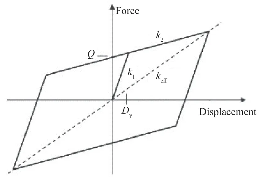
Fig.3 Bilinear force-displacement characteristics of FPS
More specifically,the coefficient of friction increases exponentially with increasing sliding velocity up to a specific value of sliding velocity,and after that,it remains nearly constant.Larger axial pressure at the sliding interface reduces the friction coefficient at high sliding velocity,whereas the friction coefficient at low velocity remains unchanged (Constantinouet al.,1990).The coefficient of friction decreases swiftly as the temperature at the sliding interface increases from-40°C to 20°C,and thereafter gradually decreases until it attains a constant value for temperatures beyond 250°C (Kumaretal.,2015).The friction pendulum isolation systems shift between sliding and sticking phases,during which two different frictional forces are generated.The coefficient of friction attained at the initial phase of sliding and motion reversals are 1.5 to 4.5 times greater than the friction value at sliding,subject to the friction material used to coat the slider(Mazza and Mazza,2017).The high friction coefficients during the initial sliding phase and motion reversals and the transition of friction coefficients during the stick-slip phase can result in unforeseen superstructure responses if not correctly accounted for in modelling (Fagaet al.,2016).Manufacturers such as FIP Industriale are currently using innovative sliding materials to reduce stick-slip while lowering the ratio of break-away to dynamic friction coefficients (see: https://www.pretensa.com.pt/upload/pdf/content_our_work/FZhd5uLx/S04_FIPFIPD-eng.pdf).
The parameters characterizing the bilinear curve are elastic stiffness,characteristic strength and the postyield stiffness.In an FPS,the force required to produce a displacementDin the direction of earthquake shaking is given by;

The effective stiffness at a displacementDis given by;

Elastic stiffness is given by;

whereμis the coefficient of friction,Wis the axial load on the isolator,Dis the horizontal displacement,Ris the radius of curvature andDyis the yield displacement of the isolator.
Post yield stiffness is given by;

The characteristic strength (Q) reflects the stability of the hysteretic behavior of the bearing under numerous cycles of loading.The effective damping ratio of the bilinear system is determined by equating the energy dissipated by one cycle of the bilinear hysteretic response with the energy dissipated by one cycle of the viscously damped elastic structure at equal displacement.The effective damping ratio is given by;

3 Description of analyzed rack structure
The considered rack structure is a four-shelf,twobay,heavy-duty rack,with a story height of 1.3 m and bay width of 1.4 m,as shown in Fig.4.The crosssection of the uprights and pallet beams are adopted from Saravananet al.(2014),the dimensions of which are presented in Figs.5(a) and 5(b),respectively.The bracings are lipped channel sections,as depicted in Fig.5(c).

Fig.4 Schematic view of the analyzed selective pallet rack (mm)

Fig.5 Cross-section of components (mm)
4 Characterization of base-isolated rack systems considered in the analysis
The base-isolated variant of the rack structure is characterized by identical friction pendulum bearings of the same radius of curvature,placed below each upright.Three different radii of curvature of 0.995 m,1.555 m,and 2.239 m are chosen for the FPS,one at a time,corresponding to a natural time period of 2.0 s,2.5 s and 3.0 s,respectively.
The seismic response of selective pallet racks is substantially influenced by the pattern of the positioning of the pallets on the racks as well as the total pallet mass placed on the system.In order to assess the seismic performance of racks isolated with FPS under a range of loading,three different pallet masses of 1000 kg,500 kg and 250 kg are placed on the rack,in two different mass configurations.It is assumed that only one mass condition acts on the rack at a time.
The first loading configuration consists of identical pallets placed symmetrically on all shelves (see Fig.6(a)).In the second mass configuration,identical pallets are positioned on the right bay,as shown in Fig.6(b).The peak response is expected to occur in the first mass configuration with the identical pallets placed on all shelves.The first loading configuration is considered for all the FPS variants with a radius of curvature of 0.995 m(T=2.0 s),1.555 m (T=2.5 s),and 2.239 m (T=3.0 s).The second mass configuration is considered for the baseisolated rack with a radius of curvature of 1.555 m (T=2.5 s)only.The asymmetrical mass configuration is chosen to examine the effectiveness of FPS in minimizing the harmful torsional motions.

Fig.6 Mass Configurations considered
It is questionable whether an FPS that provides seismic isolation only in the cross-aisle direction or in all directions should be used.The isolation system developed by Filiatraultet al.(2008) provides seismic isolation only along the cross-aisle direction with fixed support in the down-aisle direction,allowing for more storage space.Furthermore,the fundamental period in the down-aisle direction is already high,and there is no reason to increase it further through seismic isolation,as stated before.Mass irregularity in structures isolated by FPS may induce torsional motion due to the differences in the friction coefficients of the FPS beneath each column caused by differences in axial load (Saittaet al.,2018).If the FPS is altered to provide unidirectional isolation along the cross-aisle direction,the possibility of torsional twisting of uprights increases,particularly when the mass distribution is uneven.As a result,in this work,racks are isolated using FPS in the conventional manner,with the isolator free to move in all directions along the horizontal plane.
Furthermore,the friction coefficients for each isolated base variant with a given mass arrangement are based on two distinct friction characterization studies.This constitutes eighteen base-isolated variants in the first mass configuration,corresponding to the three natural time periods (or radius of curvature),the threepallet mass and the two different friction coefficients.Similarly,six base-isolated variants are considered in the second mass configuration,for the combinations of a natural time period of 2.5 s,three pallet masses and the two different friction coefficients.Table 1 summarizes the 24 base-isolated variants that have been considered in this study.

Table 1 Details of isolated racks considered
5 Finite element analysis
5.1 Superstructure modelling considerations
The SAP2000 (2017) finite element program is used to model the base-isolated and fixed base structures.All superstructure frame elements such as uprights,beams and bracings are modelled as linear elastic elements while the friction pendulum bearings were modelled using two joint,zero-length,nonlinear link elements.The modelling approach is based on the assumption that the superstructure of a base-isolated building remains linear elastic during seismic shaking.The connections between the bracings and upright are assumed to be pinned.The stiffness of the semi-rigid beam to upright connections is assigned as 71.62 kNm/rad,as reported by Saravananet al.(2014).In addition,the moment of inertia of uprights is reduced by 15% to account for the effect of stiffness reduction due to perforations along the upright.This is aligned with the findings of the study by Saravananet al.(2014),which served as the source for the upright section used in this work.The modulus of elasticity is chosen as 20500 MPa as reported by Saravananet al.(2014).Due to the absence of horizontal cross bracings,a flexible diaphragm is assumed at all shelf levels.The merchandise weights are assigned as uniformly distributed loads on the shelf-beams.
5.2 Constitutive modelling of friction pendulum bearing
The nonlinear link elements used to model the friction pendulum bearings in SAP2000 (2017) has coupled frictional properties along the two principal shear directions.In the vertical direction,it behaves as a gap element with no tensile stiffness.To model friction pendulum bearings in SAP2000 (2017),the compressive stiffness,elastic stiffness,effective stiffness,and coefficient of friction values at high and low velocities,and the rate parameter must be specified.The software automatically generates the post-yield stiffness as well as the coupled force-displacement relationship along the two directions based on the input parameters.
The elastic stiffness of an isolator is given by Eq.(4),and the effective stiffness is calculated from Eq.(3) at the design displacement.The hysteretic behavior of the friction model in SAP2000′s isolator element is based on Parket al.(1986).The pendulum behavior is as formulated by Zayaset al.(1990).The link element in SAP2000 (2017) for modelling the friction pendulum bearing considers the variation of friction coefficient with the velocity,ignoring the effect of axial pressure.The following expression suggested by Constantinouet al.(1990) gives the variation of coefficient of friction with velocity as follows:

whereμfastis the coefficient of friction at high velocity of sliding,μslowis the coefficient of friction at a slow velocity,vis the velocity of sliding,andais the rate parameter.μslowis considered as half of the value at high velocity of sliding,μfast.The rate parameter controls the transition fromμfasttoμslow,which is adopted as 100 s/m in this study,as specified by Constantinouet al. (2007).
The friction force is given by

whereZis a nondimensional hysteresis variable that satisfies both Eq.(9) and Eq.(10) (Parket al.,1986).
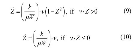
in whichkdenotes the shear elastic stiffness of the sliding material in the absence of sliding.During motion,Z=± 1,whereas< 1 during the sticking phase (Constantinouet al., 1990).
The bidirectional motion produces the following forces in two orthogonal horizontal directions:

The first term denotes the pendulum force directed towards the center of the bearing,while the second represents frictional force.μxandμyare the coefficients of friction along theXandYdirections,respectively,expressed by the following equations;

whereμfast,xandμfast,yare the friction coefficients at high velocities of sliding along theXandYdirections,respectively.Similarly,μslow,xandμslow,yare the friction coefficients at very low velocities of sliding along theXandYdirections,in that order.The resulting sliding velocity (v) is described by the equationThe effective rate parameter (a) is given bywhereaxandayare the rate parameters along theXandYdirections.
The hysteretic variablesZxandZyare adjusted in accordance with the following differential equation.

wherekxandkyare the elastic shear stiffness of the slider during the sticking phase.axandayare equal to 1 ifv x·Zx> 0 andv y·Zy> 0,respectively and otherwise equal to zero.The hysteretic variablesZxandZymust satisfy the condition
Hysteresis variables are dependent on displacement,velocity,and the initial stiffnessk1,which is fixed by the yielding displacement (Saittaet al.,2018).
Two different values ofμfastare considered under each isolator for a particular loading condition,one at a time;i.e.,for a pallet mass configuration with a specific pallet mass.The values ofμfastare given by both Eq.(16) and Eq.(17),which are adopted from Kumaret al.(2019) and Takeuchiet al.(2019),respectively.Equations (16) and (17) provide friction coefficients with mild to significant variations,respectively,for the entire range of static axial loading expected from the various pallet mass arrangements considered.In this way,the variation of coefficient of friction with axial loading is implicitly taken into account,which otherwise is ignored in modelling friction pendulum bearings by SAP2000(2017),as discussed before.
whereprepresents the axial pressure at the isolation interface,μ0represents the reference coefficient of friction which is taken as 0.047,andvis the velocity at the top of the slider,as reported by Takeuchiet al.(2019).The axial pressure is calculated by assuming an articulated slider with a bearing contact area of 30 mm diameter.A sliding velocity of 500 mm/s is considered to calculateμfastas per Eq.(17).The value of sliding velocity chosen is in agreement with the maximum sliding velocity expected for the considered isolated rack structures during a seismic event.
The coefficients of friction obtained from Eq.(16) and Eq.(17) are referred to as friction type I and friction type II,respectively,in the following sections.Table 2 presents theμfastvalues under each upright based on the two friction types for the static axial loading corresponding to different pallet mass configurations.Moreover,the elastic stiffness is calculated as per Eq.(4),consideringμslowvalues based on the two friction types for each pallet mass arrangement,and a yield displacement of 0.5 mm.The elastic stiffness based on the two friction types for various pallet mass arrangements is also reported in Table 2.The axial stiffness of the isolator element is chosen as 1.9625×10⁶kN/m.The rotational stiffness of the isolators is assumed to be fixed in both horizontal directions,while the torsional stiffness is assumed to be zero.As rotations are often small when the superstructure remains elastic,introducing rotational effects is largely unneeded (Fenz and Constantinou,2008a).
The design displacement of the FPS is determined using the design acceleration coefficient in the response spectrum of the Indian code (IS 1893 (Part1): 2016)(2016) for soft soil conditions and Zone V location.The response reduction factor is chosen as 1,assuming limited superstructure ductility for the base-isolated structure.Additionally,the importance factor is chosen as unity.As the effective stiffness and effective damping are displacement dependent,an iteration procedure is followed to obtain the design displacement for each loading condition.For the analyzed rack structure,the axial loading and subsequently coefficient of friction may be different under isolators,due to the two-bay geometry of the rack structure and the pallet mass arrangement.Therefore,the conventional iteration procedure is extended further to find the global effective stiffness and global effective damping for each iteration,from the effective stiffness and damping of each isolator(see Liuet al.,2014).The steps of the iteration procedure are presented below.
1.Estimate the weight supported by each isolator under gravity loads.
2.Calculate the equivalent linear properties,keffandζeff,of each FPS using Eq.(3) and Eq.(6) for an assumed value of initial displacement,static axial loading andμfast,for each pallet mass arrangement.
3.Calculate the global equivalent linear properties of the simplified SDOF system from the equivalent linear properties of each isolator using Eqs.(18),(19)and (20);
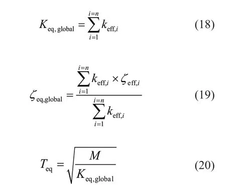
The design displacement is given by the following formula;

where,Sais the spectral acceleration corresponding toTeq,(from IS 1893 (Part 1): 2016),for soft soil conditions and Zone V location) andBis the damping modification factor for any given damping ratio.The damping modification factor for Indian sites is adopted from Suranaet al.(2019) and is given by;

4.Check the differences in the design displacement between two successive steps.If the maximum difference is less than 10%,stop the iteration.
For various mass combinations and friction types,Tables 3 and 4 indicate the design displacements of the isolated racks,as well as the effective stiffness of the central and side uprights at the design displacement.
5.3 Analysis scheme
Fast nonlinear analysis (FNA) (Wilson,2004) is carried out to examine the seismic response of pallet racks isolated with FPS,under the assumption that nonlinear response is limited to the isolator elements.Mode shapes are calculated as load-dependent Ritz vectors in FNA,and that mode shapes orthogonal to the loading are discarded in FNA (Giammonaet al.,2015).A sufficient number of 75 modes are considered to adequately describe the dynamic characteristics of the isolated structure.In the present study,all modes associated predominantly with superstructure deformations are assigned a 5%modal damping.In modal analysis,these are structural modes that appear following the isolation modes.Below the fundamental frequency of the superstructure in the fixed base condition (isolation modes),zero damping is specified. Therefore,in the isolation modes,all of the energy dissipation results from the hysteretic energy dissipation of the isolators only (Pantet al.,2013).A 99.9% modal damping ratio is assigned to the last six modes,which are high-frequency modes associated with the vertical excitation of isolators (see: Example 6-11,SAP2000 (2017) Verification Manual).The response of the corresponding fixed-base structures is determined using a modal time-history analysis with 10% modal damping.A larger damping ratio is considered for fixed-base structures to indirectly account for energy dissipation due to pallet sliding,which would be induced by higher shelf level accelerations.(Pollinoet al.,2014).
5.4 Ground motion selection
Ground motions for time history analysis compatible with the response spectrum of the Indian code (IS 1893 (Part1):1 2016) for soft soil conditions and Zone V location are chosen from the Pacific Earthquake Engineering Research Center (PEER) database (PEER,2013).It is generally accepted that base isolation is less efficient for soft soil when compared to hard/ medium strata (Kulkarni and Jangid,2003).As a result,the seismic analysis is conducted using the design hypotheses that includes a high-risk seismic zone (Zone V) and a soft soil site to generate a greater response from the isolated structure.Artificial ground motions are generated by matching the response spectrum of the selected ground motions with the aforementioned response spectrum of the Indian code in the desirable period range of interest using the SeismoMatch (2016) program.In the case of the isolated pallet racks considered in the study,the effective natural time period varies from 1.613 s to 2.518 s,for various loading configurations,as presented in Table 6.As per ASCE 7-10 (2010),the period range of spectral matching is 0.25TDto 1.5TM,for base-isolated structures,whereTD&TMcorresponds to the effective time period in the design basis earthquake (DBE) and maximum considered earthquake (MCE).However,a lower limit of 0.1 s is chosen for spectral matching,considering the possibility of contribution from superstructure modes.Table 5 reports the characteristics of the original ground motions selected for the study.Figure 7 depicts the response spectra of the synthetic ground motions,matching with the target spectrum.

Table 2 Coefficient of friction at high velocity of sliding and elastic stiffness
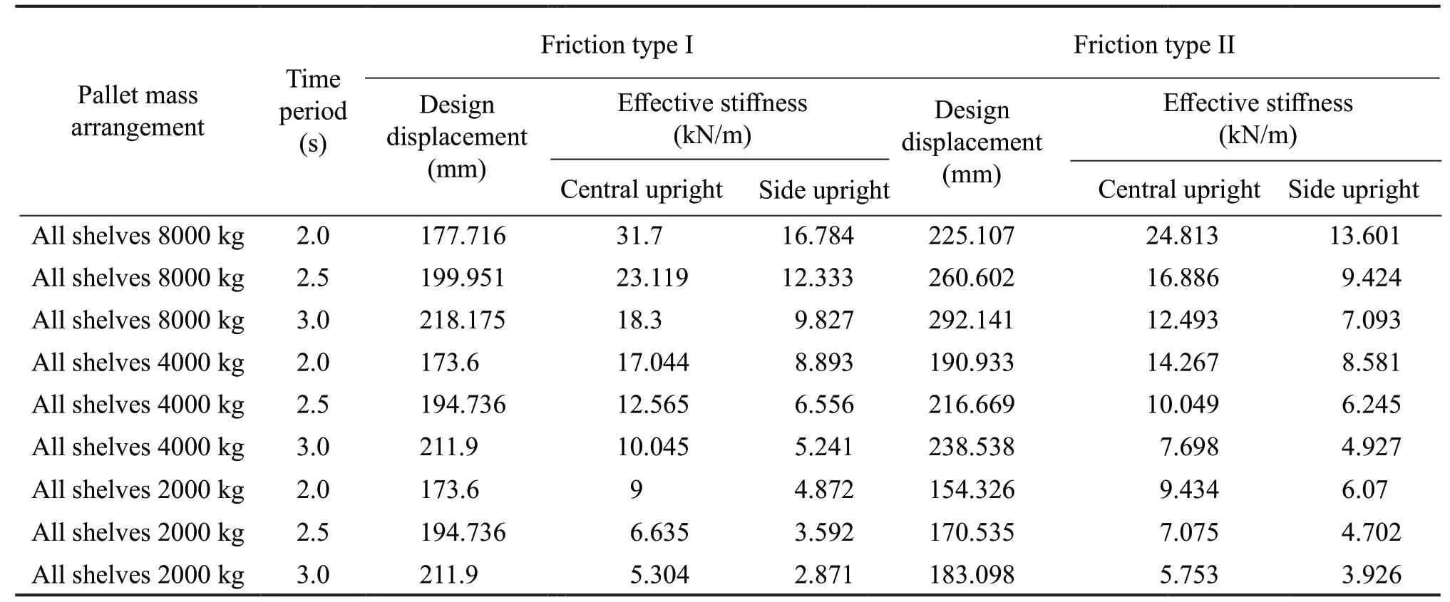
Table 3 Design displacement and effective stiffness for the first mass configuration

Table 4 Design displacement and effective stiffness for the second mass configuration
A dilemma exists whether to adopt the target response at the MCE or DBE level of shaking,as FEMA 460 (2005)does not suggest pallet shedding as part of the collapse prevention performance objective in MCE.However,it cannot be assured that pallets will not fall under MCE if it is safe in DBE.Therefore,MCE is considered as the critical hazard level,and the performance evaluation at DBE is not carried out.The latest revision of the Indian code (IS 1893 (Part 1): 2016) does not use the terminologies DBE and MCE;the authors are compelled to adopt the spectral acceleration at MCE in the same way as in the previous version of the Indian code (IS 1893 (Part 1): 2002).As a result,the design acceleration coefficient (Sa/g) for soft soil conditions is used without any multiplication factors,with the exception of the zone factor,importance factor,and response reduction factor.The Zone factor for seismic Zone V is adopted,and the importance factor and response reduction factor are both set to unity,as discussed in Section 5.2.
6 Results
The results of the parametric study are presented in terms of the engineering demand parameters such as effective time period,shelf level acceleration,isolator displacement and top-shelf drift.Seismic responses are generally understood to be lognormally distributed when sampled over a large number of ground motions (Sayaniet al.,2011).The median and dispersion of the responsexi(i=1,2,...,n) that follows a lognormal distribution are calculated using Eq.(23) and Eq.(24),respectively.The median represents the central tendency,whereas dispersion shows the degree of scattering in the data.The median plus one standard deviation,or 84th percentile value,is computed asμ.exp (δ).
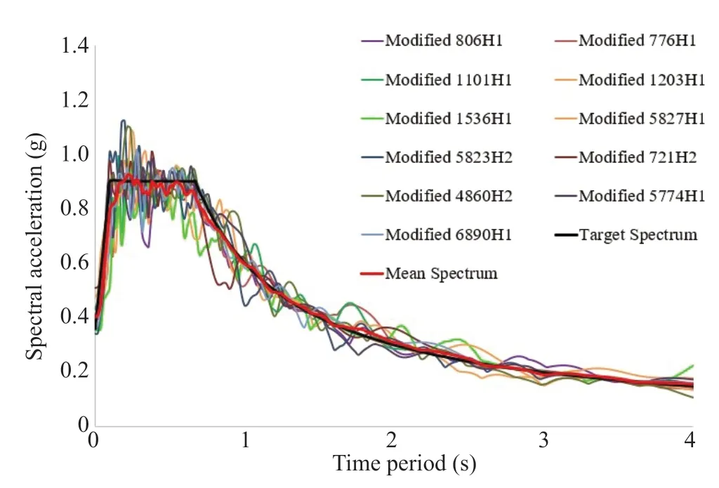
Fig.7 Response spectra of the artificially generated ground motion records compatible with target spectrum

6.1 Effective time period
Table 6 presents the effective time periods obtained from the modal analysis of base-isolated racks for the various combinations of the radius of curvature,pallet mass arrangement,and friction types.Note that if the coefficient of friction at the sliding interface is nearly equal for the static axial loads corresponding to the considered values of three pallet masses,the effective time period along the cross-aisle direction,for a given radius of curvature and pallet mass configuration,is approximately equal for the three pallet masses.This is noticeable from the third column of Table 6 for isolated racks centered on friction type I.Due to the difference in coefficient of friction between the three pallet masses investigated,isolated racks based on friction type II have different effective time periods along the cross-aisle direction for a given radius of curvature.As expected,the effective time period along the down-aisle direction is more than the cross-aisle direction due to the semirigid upright beam connections,which increases the superstructure flexibility along the down-aisle direction.

Table 5 Characteristics of the selected ground motions
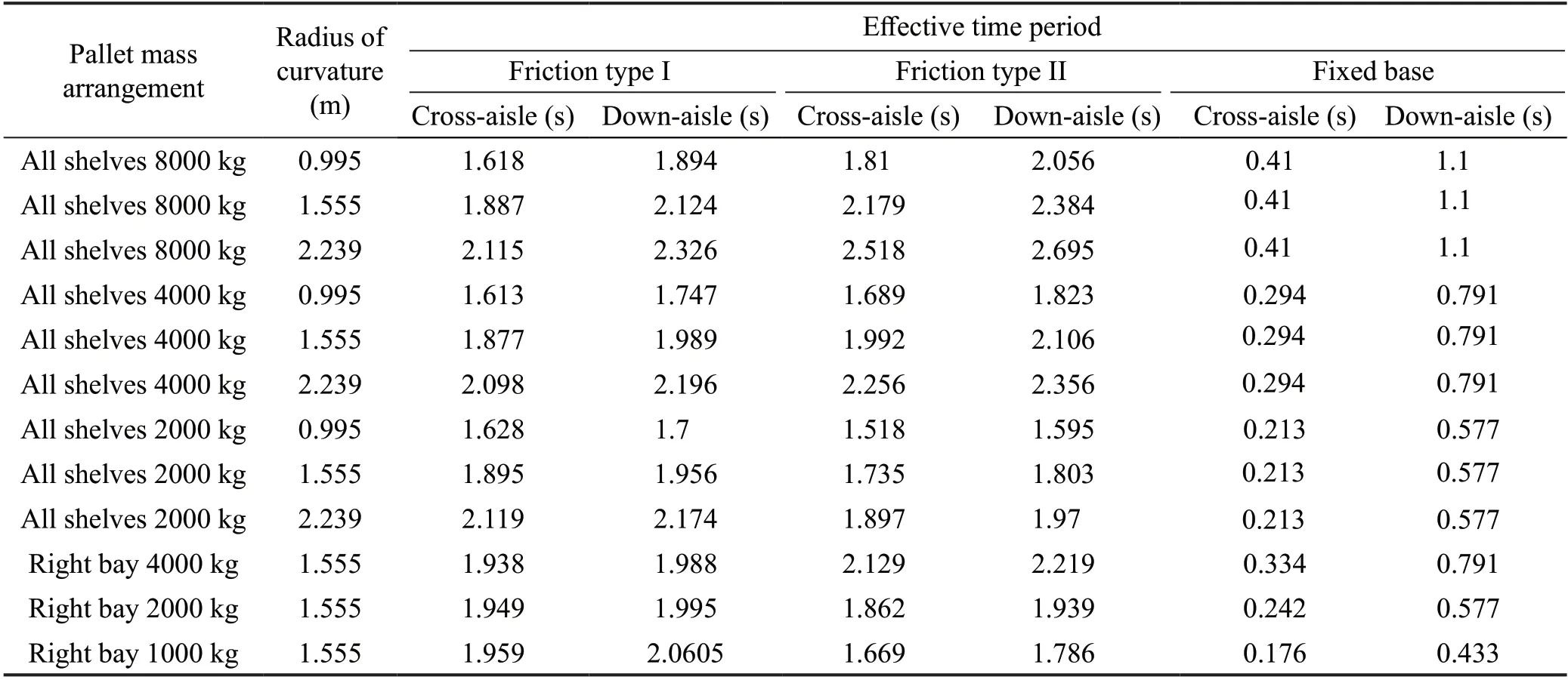
Table 6 Effective time period
6.2 Shelf level acceleration
Peak shelf level acceleration along the cross-aisle direction is a key parameter governing the effectiveness of the base isolation for selective pallet racks,as it controls the pallet shedding fragility of the racks under seismic loading.The analysis results indicate shortduration spikes in the acceleration response time history of the shelf joints,which may not generally occur in real experiments.The high-frequency oscillations in the response could be caused by the instantaneous opening and closing of the vertical gap element inherent in the friction pendulum isolator.Furthermore,the stickslip behavior may also lead to these spikes,although to a smaller extent.(see Example 6-11,SAP2000(2017) verification problem).Hence,comparing the peak acceleration responses may lead to inaccurate conclusions.To lighten this issue,the RMS of the accelerations of the six upright beam joints is calculated at every shelf for each time step,which is defined as the representative acceleration at that shelf-level.The representative acceleration can be considered the resultant or effective acceleration for each shelf level at each time step.When examining the pallet shedding fragility of racks,it is essential to consider the peak representative acceleration.
Figure 8 presents the peak representative accelerations at different shelf levels for the selected combinations of pallet mass arrangement,the radius of curvature,and friction type.The median value of peakrepresentative accelerations for all the base-isolated and the corresponding fixed-base structures,loaded in the first and second mass arrangements,across the ground motion ensemble,are presented in Fig.9 and Fig.10,respectively.The results indicate that isolated racks with a natural time period of 2.0 s (radius of curvature=0.995 m) generate more shelf level acceleration than isolated racks with time periods of 2.5 s and 3.0 s.This is apparent for most ground motions investigated,with the median and 84th percentile values demonstrating this trend very convincingly.The increase in acceleration can be attributed to the larger post elastic stiffness of the isolation systems with a smaller radius of curvature.

Fig.9 Median peak representative acceleration for isolated racks in first mass configuration (all shelves loaded)

Fig.10 Median peak representative acceleration for isolated racks in second mass configuration (pallets on right bay)
It is desirable to limit the shelf level acceleration to be within 0.35 g as this intensity of acceleration is not anticipated to cause the fall of pallets (Michael,2013).The results demonstrate that the peak representative acceleration for isolated racks withT=2.5 s andT=3.0 s is less than 0.35 g,except in a few rare instances.For all combinations of the radius of curvature,pallet mass arrangement,and friction type investigated in the study,the median peak representative accelerations are within 0.35 g.However,for isolated racks withT=2.0 s,the 84th percentile peak representative accelerations exceed 0.35 g in a few instances,whereas the values forT=2.5 s andT=3.0 s remain below 0.35 g.The dispersion in acceleration demands (reflected as the difference between the median and the 84th percentile) is higher for isolated racks withT=2.0 s and lower for isolated racks withT=3.0 s.

Fig.8 Peak representative acceleration for isolated racks in first mass configuration (all shelves loaded)
It is generally observed that isolated racks based on friction type I yield larger peak representative acceleration than an equivalent base-isolated model based on friction type II for larger pallet mass.In contrast,isolated racks centered on friction type II generate larger peak representative acceleration than those based on friction type I for lower pallet mass.The median peak representative accelerations for all the base-isolated variants,except those at the second and third shelf levels for the isolated racks withT=2.0 s and a pallet load of 8000 kg,corroborate the statement above.The increase in acceleration for racks based on friction type I might be due to the greater flexibility of the superstructure for the larger mass (Matsagar and Jangid,2004).However,the low coefficient of friction due to the larger mass for friction type II increases the flexibility of the isolation system,thereby offsetting the effect of superstructure flexibility.Additionally,the higher elastic stiffness of racks centered on friction type I for larger pallet mass increases the shelf accelerations.In contrast,the elastic stiffness of isolated racks based on friction type II is higher than that of friction type I for lighter pallet mass.Therefore,it is expected that isolators based on friction type II produce larger shelf level acceleration for lower pallet mass due to the higher elastic stiffness and coefficient of friction,which increases the stiffness of the isolation system.
The median peak representative accelerations indicate a sharp increase from the third shelf level to the fourth shelf level in isolated structures,based on friction type I,and with natural periods of 2.5 s and 3.0 s.This could be because longer isolation periods increase the nonlinearity of the isolated structure,magnifying the higher mode effects (Skinneret al.,2012).This effect is more pronounced for isolated racks with a total pallet mass of 8000 kg,where the difference in median peak representative accelerations at the fourth shelf level between isolated racks withT=2.0 s,T=2.5 s,andT=3.0 s is minimal.This is to be expected,as more mass causes the superstructure periods of the isolated structure to lengthen,resulting in an increased higher mode contribution (Chimamphant and Kasai,2016).This trend is not observed for isolated racks based on friction type II with natural periods of 2.5 s and 3.0 s and a total pallet mass of 8000 kg,due to the lower elastic stiffness of the isolated system in comparison to those based on friction type I,which reduces the nonlinearity of the isolation system even over longer isolation periods(Skinneret al.,2012).
6.3 Isolator displacement
The larger the isolator displacement,the more are the chances of the collision of racks with forklift trucks or human beings.Moreover,the larger diameter of the FPS reduces the clear space for the operation of forklift trucks between adjacent racks.Therefore,the base displacement of the FPS needs to be limited.
The maximum isolator displacement along the cross-aisle direction is found for the six isolators,and the largest of these is adopted as the peak isolator displacement for the isolated rack.The peak isolator displacement for a few variants of isolated racks loaded in the first mass configuration (all shelves loaded) is shown in Fig.11.Figure 12 displays the median value of peak isolator displacements,across the set of ground motions considered,for all the isolated racks loaded in the first mass configuration.Similarly,Fig.13 depicts the median peak isolator displacements for isolated racks with a natural time period of 2.5 s and loaded in the second mass configuration (right bay alone).

Fig.11 Peak isolator displacement for isolated racks in first mass configuration (all shelves loaded)

Fig.12 Median peak isolator displacement for isolated racks in first mass configuration (all shelves loaded)

Fig.13 Median peak isolator displacement for isolated racks in second mass configuration (pallets on right bay)
Note that for a given pallet mass arrangement,the peak isolator displacement is generally observed for isolated racks with the largest radius of curvature of 2.239 m (orT=3.0 s).This behavior is attributed to the greater flexibility of the isolation bearings with a larger radius of curvature during the sliding phase.Additionally,the results of median peak isolator displacements validate this conclusion.However,this trend is not observed in all the base-isolated variants for specific ground motions,such as the ‘Modified Iwate_Japan’,‘Modified Chuetsu-oki_ Japan’,and ‘Modified Darfield_ New Zealand’.For example,when subjected to ‘Modified Darfield’ ground motion,all isolated rack systems based on friction type I and loaded in the first mass configuration yield the largest isolator displacement when the radius of curvature is 1.555 m (T=2.5 s),followed by 2.239 m (T=3.0 s) and 0.995 m (T=2.0 s).
Isolated racks based on friction type I with a total mass of 8000 kg,loaded in the first mass configuration(all shelves loaded),yield a maximum isolator displacement of 174 mm,across all ground motions examined.In contrast,a comparatively larger peak isolator displacement of 264 mm is obtained for the analogous base-isolated models centered on friction type II.The reason for the larger displacement might be the lesser coefficient of friction for the same mass in the case of the latter.When loaded in the first mass configuration with a total pallet mass of 2000 kg,the isolated rack system based on friction type I generates a larger isolator displacement than those based on friction type II.This could be due to the higher coefficient of friction associated with the smaller pallet mass in the latter′s case.The same conclusion is applicable for the second mass configuration (shelves on the right only loaded)as well.As anticipated,the dispersion in peak isolator displacement demands is larger for isolated racks withT=3.0 s and lower for isolated racks withT=2.0 s.
The effectiveness of FPS in mitigating the torsional motion for the second mass configuration with pallets placed on the right bay is investigated by finding the differences in base displacements between adjacent isolators along the down-aisle direction at each time instant.The greatest difference,29.5 mm,is seen across all base-isolated versions loaded in the second mass configuration,in the case of isolated racks withT=2.5 s,based on friction type I and a total pallet mass of 1000 kg.However,the greatest down-aisle displacement is only a few millimetres in all cases.This concludes that global torsion about the vertical axis is not observed for the asymmetrical configuration,while a shear dominant response along the cross-aisle direction is observed.This might be due to the flexible nature of the shelf level diaphragm.Figure 14(a) presents the time history of isolator displacement for left,central and right uprights in the case of isolated racks withT=2.5 s,based on friction type I with a total pallet mass of 1000 kg,loaded in the second mass configuration.For the purpose of comparison,the time history of isolator displacements for isolated racks withT=2.5 s,based on Friction Type I and loaded in the first mass configuration with a total pallet mass of 2000 kg,is plotted in Fig.14(b).The results are presented only for the ‘Modified Kobe’ ground motion,for the two mass configurations considered,for brevity.It is clearly visible from Fig.14(b) that the left,middle and right isolators move as a group with negligible relative displacement even in the absence of a rigid bottom shelf.

Fig.14 Isolator displacement history for isolated racks based on friction type I,with T=2.5 s,under modified Kobe ground motion
6.4 Top-shelf drift
It is desirable to limit the drift of a base-isolated structure within the elastic limits to mitigate the superstructure damage and lower the unfavorable P-delta effects on the stability of the isolation system.For an isolated structure with a braced frame type superstructure,the allowable drift is limited to 0.005hs,wherehsis the height of the story level (see FEMA P-751,2009).The results show that all isolated racks generate a peak drift at the top-shelf level within the permissible limits,except for the case of FPS withT=2.0 s,based on friction type II and loaded in the first mass configuration with 8000 kg total pallet mass,under ‘Modified Kobe’ground motion.Figure 15 presents the median values of peak drift at the fourth shelf level,across the ground motion ensemble,for all the base-isolated racks loaded in the first mass configuration.The peak values of the top-shelf drift for the two mass configurations and the median drift values for the second mass arrangement are not presented for brevity.

Fig.15 Median peak top-shelf drift for isolated racks in first mass configuration (all shelves loaded)
For a fixed pallet mass,the largest drift is mostly observed for racks with the shortest natural time period (T=2.0 s) and the least for the largest natural period.(T=3.0 s).This is expected as the stiffer the isolation system (T=2.0 s),the larger the drift and vice versa.Unlike peak representative shelf-level acceleration and peak isolator displacement,higher dispersions are not necessarily seen for natural time periods for which responses are highest (T=2.0 s),in the case of peak top-shelf drift.It might be because certain base-isolated variants withT=2.5 s andT=3.0 s have response outliers for ground motions,such as ‘Modified Kobe’ and‘Modified Loma Prieta’ (both stations),increasing the dispersion of the whole sample.Note that top-shelf drift has a higher dispersion than that of isolator displacement.Because both top-shelf and isolator displacements are necessary to quantify the drift of an isolated structure,the dispersion increases with the increase in the number of parameters.
6.5 Uplift
Note that the peak uplift displacements predicted in this study are on the order of a few millimeters only.This is likely due to the fact that SAP2000 (2017) software underpredicts the uplift displacements produced by rigid body rocking of the isolators since the software performs small displacement analysis (Fenz and Constantinou,2008b).
7 Conclusion
A numerical study for evaluating the effectiveness of FPS in isolating selective pallet racks is performed.A wide range of variables is considered for the parametric study in terms of the natural time period (or radius of curvature),the total pallet mass,pallet mass irregularity,and coefficient of friction at the sliding interface.The peak shelf acceleration and isolator displacements are critical in defining the optimal radius of curvature and friction coefficient for achieving the desired performance of racks isolated with FPS.Compared to a fixed base rack,the base isolation systems included in this study could significantly reduce the shelf-level accelerations.The peak representative acceleration is well within the critical limit of 0.35 g for isolated racks withT=2.5 s andT=3.0 s for all the isolated rack variants considered,except for a few instances.In contrast,isolated racks withT=2.0 s generate peak representative acceleration of more than 0.35 g for a larger number of instances.Therefore,it is concluded that FPS characterized by a natural period of 2.0 s is inappropriate for isolating the selective pallet racks considered in the study.In the matter of peak base displacement,base-isolated racks realized with a natural period of 3.0 s generate larger base displacements than isolated racks with a natural period of 2.5 s.Consequently,FPS with a natural period of 2.5 s (radius of curvature 1.555 m) is the favorable time period for isolating the pallet rack considered,among the three time periods considered in the study,namely 2.0 s,2.5 s and 3.0 s.
The friction coefficient at fast sliding velocities is calculated from the static axial loads corresponding to each pallet mass arrangement using the equations presented by Kumaret al.(2019) and Takeuchiet al.(2019).Even though base-isolated variants based on these two friction types do not disclose a clear advantage over each other in terms of the overall acceleration response,there are notable differences in the isolator displacement.The largest isolator displacement for isolated racks based on friction type I,considering all the base-isolated variants,is 193 mm (for the second mass configuration with 1000 kg total pallet mass,under ‘Modified Loma Prieta’ ground motion (Station-‘Hollister-South &Pine’).On the other hand,a considerably larger isolator displacement of 264 mm is obtained for friction type II,among all the isolated cases considered (for the case withT=3.0 s and 8000 kg total pallet mass placed in the first configuration,under ‘Modified Kobe’ ground motion).
The research shows that the isolator displacement demands and,consequently,the superstructure′s responses are sensitive to individual ground motions.For illustration,the mean peak isolator displacement for all the base-isolated variants investigated in the first mass configuration (all shelves loaded) is 166 mm (for the base-isolated variant withT=3.0 s,loaded with 8000 kg,and friction type II).However,for the same base isolated system,three ground motions,namely ‘Modified Loma Prieta’ (Station-‘Hollister-South &Pine’),’ Modified Kobe’,and ‘Modified Superstition Hills-02’,generated significantly larger peak isolator displacements of 261 mm,264 mm,and 240 mm,respectively.The remaining eight ground motions resulted in a maximum isolator displacement of less than 170 mm,with three responses less than 140 mm.Furthermore,these findings cast some doubt on the common perception that adopting spectrum matched ground motions results in less dispersed structural responses (Xieet al.,2018).The sensitivity of responses to specific ground motions is further illustrated by results that diverge from the overall pattern of the median response of isolated systems with different radius of curvature.For instance,the study has shown that as the radius of curvature increases,so do the median isolator displacements.However,‘Modified Darfield’ground motion yields a larger isolator displacement at a radius of curvature of 1.555 m,as opposed to a larger radius of curvature of 2.239 m,for all the baseisolated systems with Friction Type I and loaded in the first mass configuration.Indeed,similar anomalies for specific ground motions have been reported in the work of Deringöl and Güneyisi (2019).
It is observed that the asymmetrical mass configuration considered in the study (pallets on the right bay) generates a shear dominant response along the cross-aisle direction without global torsion,due to the diaphragm flexibility of racks.
The present work has provided insights and clarifications on how the isolator characteristics such as radius of curvature and coefficient of friction must be tuned for fitting FPS as a viable solution for isolating selective pallet racks.Due to the constraints imposed by the analysis method,the authors made no attempt to incorporate the effect of the friction coefficient on the uplift behavior in this part of this study.An isolated rack structure should experience less uplift force than a fixed base rack due to the reduced shelf level accelerations.Nevertheless,the uplift forces can be significant enough to cause concern for base-isolated structures with large aspect ratios when ground motion is intense.Therefore,it is advisable to accommodate specific uplift limiting measures,particularly for single entry racks.Before drawing any firm conclusions,more research into the uplift potential of selective pallet racks isolated with sliding isolation systems is needed,taking into account variable aspect ratios of racks,pallet masses,friction coefficients,and ground motion intensity.Additionally,future studies must account for the variation of coefficient of friction with respect to the axial force at each time instant.
杂志排行

Earthquake Engineering and Engineering Vibration的其它文章
- Innovative mitigation method for buried pipelines crossing faults
- Reliability and sensitivity analysis of wedge stability in the abutments of an arch dam using artificial neural network
- Study on time-varying seismic vulnerability and analysis of ECC-RC composite piers using high strength reinforcement bars in offshore environment
- Optimization of design parameters for controlled rocking steel braced dual-frames
- Effects of timber infill walls on the seismic behavior of traditional Chinese timber frames
- Steel rings as seismic fuses for enhancing ductility of cross braced frames