Seismic behavior assessment for design of integral abutment bridges in Illinois
2022-04-15DerekKozakLarryFahnestockandJamesLaFave
Derek L. Kozak, Larry A. Fahnestock and James M. LaFave
1. KPFF Consulting Engineers Inc, 1601 Fifth Avenue, Suite 1600, Seattle, WA 98101, USA
2. Dept. of Civil and Environmental Engineering, Univ. of Illinois Urbana-Champaign, Urbana, IL 61801, USA
Abstract: Integral abutment bridges (IABs) minimize deterioration and degradation of the abutment seats and bearings due to water, dirt, and deicing chemicals by eliminating bearings and expansion joints. Although the continuity between superstructure and abutments in an IAB is beneficial for reducing maintenance costs, it leads to more complex behavior under strength and service loading (temperature and traffic) and extreme loading (earthquake). The coupling of superstructure and substructure behavior necessitates system-level analysis of IABs. Prior seismic IAB studies have typically investigated the behavior of individual IAB components, however a gap of knowledge has developed due to the lack of studies and investigation about the behavior of all IAB components and their interactions with each other in a single analysis model. This study uses nonlinear static and dynamic analyses to investigate and assess the seismic behavior of IABs typical to the state of Illinois. The analyses aim to bridge the gap of knowledge by evaluating IABs as a whole and utilizing the results to indicate potential vulnerabilities in the design and construction of IABs in Illinois during design-level and larger seismic events, which could not be identified by component-level IAB analyses alone.
Keywords: structural analysis; seismic design; bridge design; structural models; seismic analysis
1 Introduction
Integral abutment bridges (IABs) have become increasingly popular in the United States, and IABs are now the standard bridge of choice in the majority of states (Quinn and Civjan, 2017), including the Midwestern state of Illinois. The popularity of IABs has led to an increased need to understand their behavior under a variety of loads. IAB behavior under thermal loading has been extensively studied in the past (Burdetteet al., 2004; Paulet al., 2005; Xuet al., 2007; Huanget al., 2008; Williamet al., 2012; Civjanet al., 2013), as well as in recent years for the case of bridges in the state of Illinois (Olsonet al., 2013; LaFaveet al., 2016, 2021). However, examination of the seismic behavior of IABs as an entire system has not been nearly as prevalent.
IABs differ from more typical seat-type abutment bridges by providing integral connections between the girders and abutments, as opposed to having the girders sit atop elastomeric bearings on the abutments (IDOT, 2012a, 2012b). The integral connection is formed by monolithically casting the abutment concrete around the girder (IDOT, 2012a). This method is advantageous in that it eliminates the seat and bearings (and associated expansion joint), which reduces deterioration of the girder at the seat due to water, dirt, and deicing chemicals (Kunin and Alampalli, 1999). However, as a result, the abutment becomes much stiffer and inertial forces are transmitted to the abutment foundation during earthquake response, which can damage abutment components. Although only a single row of piles is typically used, in order to increase abutment foundation flexibility under service conditions, there have still been indications of significant damage caused to IABs in earthquakes at the abutmentpile interface (Waldinet al., 2012; Wood, 2015) and at the superstructure-abutment interface (Itani and Peckan, 2011). The complex behavior at the abutments affects the rest of the structure as well during an earthquake, such as by increasing pier damage (Waldinet al., 2012). The interdependence of damage and other limit states being reached has also been observed in various non-integral abutment bridge studies (Wanget al., 2012; Ghotbi, 2014). This provides justification for studying IABs as an entire bridge system, similar to past studies of seattype abutment bridges, as opposed to only as individual components that are part of a bridge assemblage.
Most previous seismic IAB studies have focused on the behavior of a single aspect / component, such as soil-structure interaction (SSI) (Spyrakos and Loannidis, 2003; Kotsoglou and Pantazopoulou, 2009; Vasheghani-Farahaniet al., 2010; Zhaoet al., 2011; Franchin and Pinto, 2014; Fiorentinoet al., 2020), the abutmentpile interface (Froschet al., 2009; Fiorentinoet al., 2020), or the superstructure-abutment interface (Itani and Peckan, 2011). The seismic behavior of individual IAB components and their interactions with each other has not been extensively studied in the past, although it has generally been noted that strong participation of the abutment and backfill soil can significantly influence and effectively reduce the seismic demand on bridges and that integral bridges tend to perform better from a seismic perspective than their jointed bridge counterparts (Aviramet al., 2008; Mitoulis, 2012; Ni Choineet al., 2015). This leads to an existing gap in knowledge between how IABs perform under seismic loads at the component-level and at the system-level, with extensive research being completed at the component-level, but only minimal research for IAB behavior as a whole system.
This study aims to bridge the gap of knowledge and identify the effects that critical bridge parameters have on the seismic behavior of entire IABs, as well as to assess IABs under seismic loading and determine design implications and recommendations for better implementation in seismic regions such as southern Illinois. These effects and design implications are not based on the behavior of a single IAB component, but rather on the behavior of the IAB as a whole system, accounting for the individual component behaviors and their interactions with each other. This process has previously been performed on non-integral abutment (stub abutment) bridges (Filipovet al., 2013b; Luoet al., 2017, 2021) and on individual IAB component behavior, as mentioned above. However, the aim of incorporating all IAB components and behavior into a single bridge system model for seismic analysis differentiates this study from past ones.
2 Parametric study overview
With an aim of the study being to assess effects of various bridge parameters on overall seismic behavior of IABs, the parametric study reported in this paper represents the most common IAB scenarios in the state of Illinois, based on discussions with the Illinois Department of Transportation (IDOT) and an examination of the southern Illinois bridge inventory. Southern Illinois is of particular interest in this study due to its proximity to the New Madrid seismic zone and the popularity of using IABs by IDOT. The specific location being studied is the city of Cairo, Illinois, which is the furthest south location in Illinois and has the largest seismic hazard in the state.
Five bridge parameters are varied, and their effects on seismic IAB behavior are studied. These parameters are the span configuration, superstructure type, pier height, bearing layout, and foundation soil type. This results in 51 distinct bridge designs, provided in the matrix of Fig. 1, which are based on actual designs of recent IDOT bridges in the region. The IAB naming convention is provided in Fig. 2.

Fig. 1 IAB parametric study matrix

Fig. 2 IAB naming convention

Fig. 3 (a) Elevation view and (b) visualization of the IAB model for a three-span bridge
The span configuration and superstructure type are related in that the superstructure girder is designed to accommodate the desired span. Five combinations of span and superstructure are studied. The single-span steel superstructure (Ss in the naming convention) utilizes six 1.778 m (70 in.) deep plate girders to span a single 48.77 m (160 ft) span. Two three-span IABs are studied, which have a span configuration of 24.38 m (80 ft) exterior spans and a 36.58 m (120 ft) center span; both steel (St) and concrete (Ct) superstructures are included. The steel superstructure comprises six 1.016 m (40 in.) deep plate girders, and the concrete superstructure comprises six IL54-2438 precast prestressed concrete (PPC) girders. Two four-span IABs are also included, which have 44.20 m (145 ft) exterior spans and 48.77 m (160 ft) interior spans. They are also studied with steel (Sl) and concrete (Cl) superstructures consisting of eight 1.524 m (60 in.) deep plate girders and seven IL72-3838 PPC girders, respectively.
Short and tall pier heights are also considered: 4.572 m (15 ft – “15” in the naming convention) and 12.19 m (40 ft – “40” in the naming convention). The bearing layout consists of all intermediate piers having either IDOT Type I elastomeric bearings (E) or lowprofile fixed bearings (F). The final parameter is the soil condition, which represents either realistic stiff (H) or soft (S) bounds for southern Illinois (based on Luoet al., 2016), or else alluvial soil conditions realistic to Cairo based on boring logs (A) (Kozaket al., 2019).
Across all 51 bridge designs, a deck width of 13.16 m (43 ft-2 in.) and deck thickness of 203 mm (8 in.) is consistently used. The St, Sl, Ct, and Cl IABs utilize 15-a, 20-d, 13-b, and 18-d IDOT Type I elastomeric bearings, respectively, along with 32 mm, 51 mm, 25 mm, and 38 mm (1.25 in., 2 in., 1 in., and 1.5 in., respectively) diameter anchor bolts for the fixed bearings and elastomeric bearing side retainers. Side retainers are components intended to prevent excessive transverse displacements of elastomeric bearings; they act as fuses when anchor bolt yielding and fracture occur. The short piers consist of four 0.762 m (30 in.) diameter reinforced concrete columns, while the tall piers consist of four 0.914 m (36 in.) diameter reinforced concrete columns. The short and tall piers were reinforced with twelve (12) #10 reinforcing bars and fourteen (14) #11 reinforcing bars, respectively.
For all Illinois IABs, the IDOT Bridge Manual (IDOT, 2012a) recommends constructing a single row of abutment piles oriented such that there is weak axis bending when subjected to longitudinal loads. This is done in an attempt to increase the flexibility of the abutment foundation, in order to offset the increased stiffness of the integral abutment and superstructure.
All designs are made to satisfy the IDOT Bridge Manual (IDOT, 2012a) and AASHTO (2011) Guide Specifications, and they are based on recent Illinois IAB designs as provided by IDOT. The general bridge design properties, which remain consistent across the parametric study, are provided in Table 1. The variety of designs allows for observations and recommendations to be made based on the seismic assessment of every design.
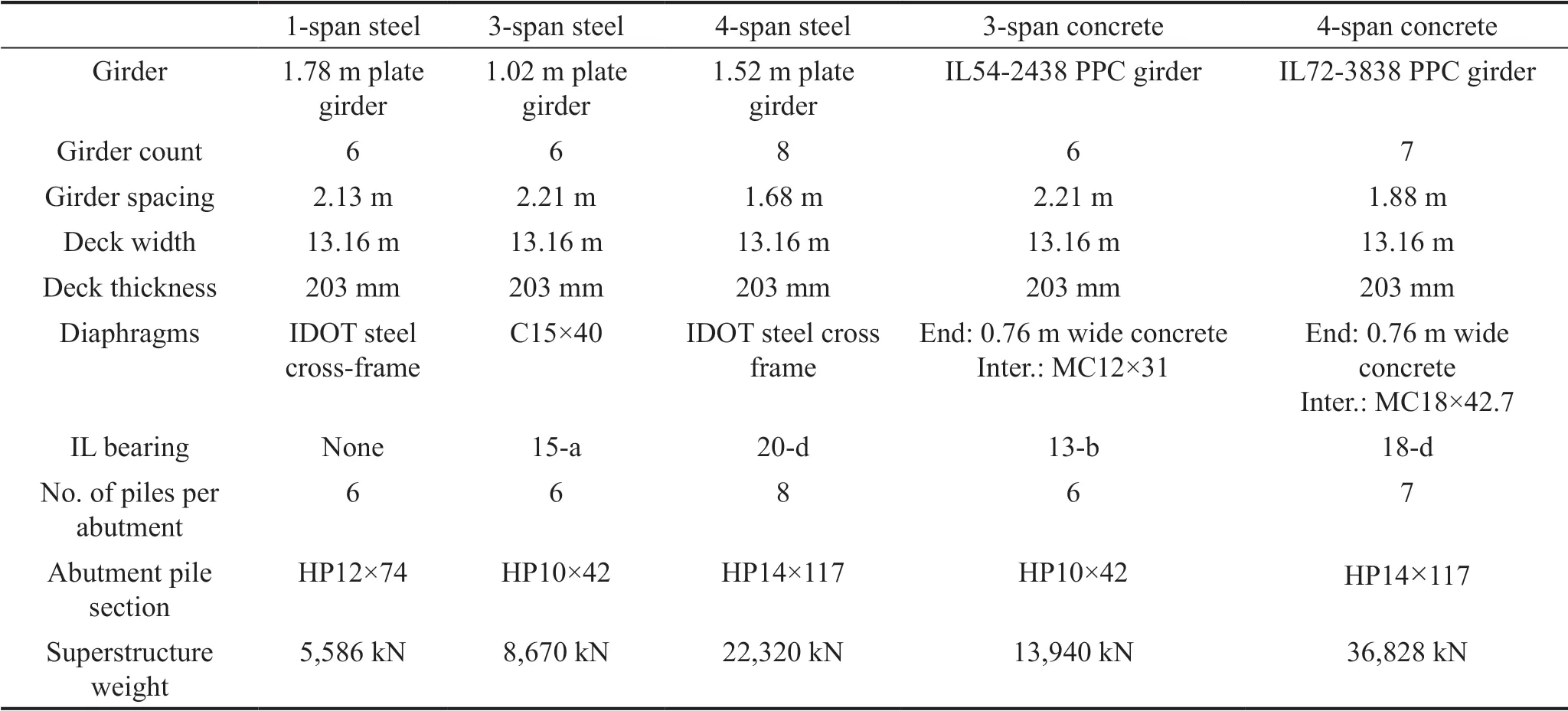
Table 1 Bridge design properties
3 IAB modeling
All IABs in the parametric study are modeled and analyzed in OpenSees (McKennaet al., 2006). The IAB models have been developed to capture the nonlinear behavior of all critical components within the bridge. System-level modeling for IABs captures the complex coupled superstructure-substructure behavior while also tracking the response of critical components during response history analysis. An elevation view and schematic representation of a threespan IAB model is presented in Fig. 3, along with the locations of key modeled components. The modeled components that account for nonlinearity and other realistic behavior include the elastomeric bearings and side retainers, low-profile fixed bearings, pier columns, abutment and pier piles, soil surrounding the abutment and pier piles, backfill behind the abutment, pile capabutment connections, and girder-abutment connections. Descriptions of the nonlinear model components are briefly provided below and discussed in more detail in Kozaket al.(2018) and LaFaveet al.(2018); while the general modeling approach is similar to that presented in those articles, the five key IAB parameters investigated in this current work have not previously been studied.
The elastomeric bearings are modeled based on Filipovet al.(2013b) considering typical elastomeric bearings used in Illinois. The elastomeric bearing model includes an initial stiffness region until friction is overcome and a slip occurs, followed by sliding at a lower kinetic friction force. Adjacent to the elastomeric bearings in the transverse direction are side retainers. The retainer behavior is closely tied to its anchor bolt behavior, and once engaged, the retainer experiences roughly elasto-plastic behavior with anchor bolt yielding and fracture (Filipovet al., 2013a). Similar to the retainers, fixed bearing behavior is also primarily based on its anchor bolt behavior with elasto-plastic behavior, yielding, and fracture (LaFaveet al., 2013). Design of the bearing and retainer models are based on experimental results from an earlier stage of this study, as reported on by Filipovet al.(2013a, 2013b) and LaFaveet al.(2013). These component models have been shown to accurately represent the bearings and retainers used in Illinois bridges.
The reinforced concrete columns at the piers are modeled using distributed plasticity models, which divide the columns into three regions, with the top and bottom being plastic hinge regions and the center being an elastic region. The plastic hinge regions are modeled using fiber elements with the fibers having properties corresponding to reinforcing steel, confined concrete, or unconfined concrete depending on the location in the cross-section. Concrete and steel are modeled using the Concrete02 and Steel02 materials, respectively, in OpenSees. The length of the plastic hinge regions (lp) is determined by Eq. (1), whereLis the distance from the critical section to the point of contraflexure,fyis the reinforcing steel yield strength,dbis the reinforcing bar diameter, andcf′ is the 28-day concrete compressive strength (Berryet al., 2008).

The integral abutments themselves contain a number of modeled components, as shown in Fig. 4. This figure provides a comparison between an isometric layout of the integral abutment area and how it is represented in the model. Individual abutment-area components are listed in the legend of Fig. 4(b) and described in more detail in this section. Even further detail about each component model can be found in Kozaket al.(2018).
The piles in both the abutment and pier foundations are modeled as a series of nonlinear beams represented by fiber elements. The fiber elements represent the geometry of the pile cross-sections as well as the Giuffré-Menegotto-Pinto model for steel material (Steel02 in OpenSees) with expected yield and ultimate stress values. The pile elements are shorter and more frequent near the top of the piles in order to capture the increased stresses and nonlinear behavior in that region. At the ends of the individual pile elements arep-y(lateral) andt-z(vertical) springs that represent the typical soil properties in the region determined through boring log records. Thep-yspring behavior of clay and sand layers are determined based on the undrained shear strength (from standard penetration test results) and the effective friction angle, respectively, of each soil layer. Thep-yandt-zsprings are modeled using the PySimple1 model in OpenSees.
The backfill against the abutments is modeled using nonlinear springs attached at two points along the height of the abutment. The nonlinear spring properties are based on typical backfill properties in Illinois (provided by IDOT, which may be found in Kozaket al.(2018)), with soil mobilizing in a logarithmic spiral failure surface while also considering a hyperbolic stress-strain behavior of the soil. This model type is known as an LSH model and simulates the passive backfill pressure against the abutment by using the force-displacement relationship provided in Shamsabadiet al. (2005, 2007). The model of the backfill is based on a modified version of the HyperbolicGapMaterial in OpenSees and is shown in Fig. 5 when subjected to cyclic movements. Unlike non-integral abutments that allow for some superstructure movement before the backfill engages, there is no gap in IABs, resulting in any movement towards the abutment engaging the backfill soil. The soil mobilizes when the failure surface is formed and provides its ultimate force resistance. Once the soil mobilizes, the backfill spring allows for unlimited deformation at the ultimate resistance force. This behavior only applies when the abutment is compressed into the backfill. There is no resistance to the abutment pulling away from the backfill. The backfill soil model only considers seismic effects and does not consider any softening from thermal cycling that may occur prior to a seismic event. This is an area of ongoing and future interest, as some recent studies have shown thermal effects to affect backfill seismic behavior (e.g., Tsinidiset al., 2019).

Fig. 4 (a) Integral abutment isometric view, (b) integral abutment modeled view

Fig. 5 Sample backfill spring model behavior
The connections between the pile caps and abutments, as well as between the girders and abutments, is also modeled. The pile cap-abutment model is based on dowel shear and concrete-to-concrete friction between the two components. The girder-abutment connection is initially modeled as pinned to simulate its flexibility before the concrete sets. During service, the girder-abutment connection is assumed rigid due to the abutment concrete encasing the girders.
Results from the IAB models have been compared to field observations of IAB damage after earthquakes in Kozaket al.(2018). The field observations of Waldinet al.(2012) and Wood (2015) indicate that a main location of damage is at the abutment-pile interface and in the piers. These damage locations match common early damage locations from the model analyses.
3.1 Limit states
Direct modeling of individual bridge components – instead of aggregating the behavior of multiple components into a simplified set of nonlinear springs – allows for limit states to be monitored explicitly in order to determine which components are damaged, the extent of damage, and the sequence of damage. While these limit states have certainly been studied on their individual components in the past, this study aims to provide insight on how IABs behave as a whole system and how the individual components and their limit states interact and contribute to the overall behavior.
The limit states are separated into three categories, depending on their desirability – ideal, acceptable, and unacceptable. Ideal limit states act as fuses and protect critical bridge components; they are typically associated with damage contained in components that are easily replaceable. Acceptable limit states do not involve severe damage, however the damage occurs in components that are more difficult to inspect or replace. Unacceptable limit states are those involving severe damage that renders the bridge unusable by emergency services immediately after an earthquake. Table 2 presents the monitored limit states, their abbreviations, and their categories. Limit states are described in further detail below as well as in Kozaket al.(2018) and LaFaveet al.(2018).

Table 2 Limit states of the IAB model
Nine limit states are classified as ideal. Backfill mobilization (BF) occurs when one of the backfill springs achieves its ultimate capacity and the spring allows for deformation without any additional force. Three retainer limit states are included: engagement (RE), yielding (RY), and fusing (RF). Engagement occurs when the gap between the bearing and side retainer is closed. Retainer yielding and fusing occur when the anchor bolt of a side retainer yields and fractures, respectively. Similar limit states are found in fixed bearings, with their anchor bolts being capable of yielding (FY) and fusing (FF). Bearing sliding (BS) occurs when a bearing reaches the kinetic/sliding portion of its bearing friction behavior. Light pier column damage occurs in the reinforcing steel (SL) when tensile strain exceeds 0.0021, and in the unconfined concrete (CL) when compressive strain at the exterior column fiber exceeds 0.002 (Kowalsky, 2000).
Eight limit states are classified as moderate. Moderate damage to the column reinforcing steel (SM) occurs at tensile strains exceeding 0.015, and moderate damage to the column unconfined concrete (CM) occurs at compressive strains exceeding 0.005. Yielding of the abutment piles (APY) or pier piles (PPY) is indicated by yielding of the material in any of the fibers of the steel pile cross-section. Abutment piles may also experience local buckling (APB) which is estimated to occur when the strain in any pile fiber exceeds 20 times the yield strain (based on Froschet al.(2009)). The soil surrounding the piles may also be mobilized (APS, PPS) by soil springs achieving their force capacity and allowing further deflection with minimal extra force. Failure of the dowels linking the pile cap and abutment indicates failure at this interface (PA).
Four limit states are classified as being unacceptable due to a likelihood of collapse of the bridge should they occur. Bearing unseating (BU) occurs when bearing displacement exceeds seat length in either direction. Severe damage to the reinforcing steel (SS) or unconfined concrete (CS) of the pier columns is achieved if the steel tensile strain exceeds 0.06, or if the concrete compressive strain exceeds 0.018. While not necessarily leading to collapse, rupture of any abutment piles (APR) can lead to the bridge becoming extremely dangerous to use. Pile rupture is identified by the pile steel reaching 40 times the yield strain.
4 Static pushover analysis
Static pushover analyses are performed on the IAB models to identify trends in IAB behavior when subjected to lateral loads. These pushover analyses monitor component limit states throughout the response to determine the sequence of limit state occurrences, how the limit states interact, and how they influence overall IAB system behavior.
4.1 Pushover analysis procedure
The pushover analysis is displacement-controlled and conducted by specifying a displacement increment on a control node (the center-most node of the model at the deck level) and recording the lateral load required to achieve the displacement increment. The applied lateral load is distributed across the IAB model in proportion to the distribution of mass in the bridge. The analysis is performed until an unacceptable limit state is reached, indicating the bridge is not serviceable after an earthquake. Pushover analyses are performed in both the bridge longitudinal and transverse directions.
4.2 Pushover analysis results
The static pushover analysis results indicate trends in IAB behavior that are insightful for understanding the more complex dynamic response when subjected to ground shaking. Representative pushover curves are presented in Fig. 6 to illustrate typical behavior across all IABs analyzed. The provided pushover curves are for the ClC15EA and ClC40EA IABs in the longitudinal (Fig. 6(a)) and transverse (Fig. 6(b)) directions.
In the longitudinal direction (Fig. 6(a)) it is observed that yielding of the abutment piles (APY) and mobilization of the soil surrounding the abutment piles (APS) are the first limit states to occur – leading to a decrease in overall IAB stiffness that is observed as a change in slope of the pushover curves. After damage to the initial abutment foundations, light damage to the pier column concrete (CL) and reinforcing steel (SL) occurs, followed by moderate damage (CM and SM). It is important to note that the peak longitudinal force resisted by the IAB occurs at roughly the same point as CM. This is attributed to the CM limit state being closely tied to spalling of the pier column concrete, which limits the amount of load the columns can carry beyond that point. Another trend to note is the occurrence of abutment pile local buckling (APB) and rupture (APR) before severe damage to the pier columns (CS or SS) in IABs with taller piers, stiffer soils, or shorter spans. This is due to the increased stiffness of the abutments relative to the piers, leading to the abutments experiencing larger forces.
The transverse pushover analyses (Fig. 6(b)) exhibit similar trends to the longitudinal pushover analyses. An exception to this is the additional engagement of elastomeric bearing side retainers and fixed bearings, which impact IAB behavior in similar ways. Side retainers increase IAB stiffness at low displacements, upon retainer engagement (RE); when retainer yielding (RY) or fixed bearing yielding (FY) occurs, stiffness reduces. The pushover curve then illustrates light, moderate, and severe pier column damage. Abutment damage also occurs (APY, APB, APR), at larger displacements than in the longitudinal direction, which causes severe pier column concrete damage (CS) to be the first unacceptable limit state reached. Increased abutment foundation damage, due to the lack of backfill contribution in the transverse direction, makes the abutments much less stiff than the piers and experience less force.

Fig. 6 General trends of limit state occurrence in the (a) longitudinal and (b) transverse pushover analyses
4.3 Pushover analysis observations
The pushover analysis results relate limit states in vulnerable components to critical IAB parameters. The first observation, as noted earlier, concerns the occurrence of damage to the pier columns and abutment foundations in nearly every IAB pushover analysis. This indicates that these components are the most vulnerable during the application of lateral loads. This observation also matches the post-earthquake field observations of Waldinet al.(2012).
Within the abutment foundations, it is observed that buckling and rupture of the abutment piles (APB and APR, respectively) are more prevalent and occur at lower control node displacements in IABs with taller piers, stiffer soil conditions, and shorter spans. These observations can be seen in Fig. 7(a) (where the pier height is varied), Fig. 7(b) (where the abutment soil conditions are varied), and Fig. 7(c) (where the span configuration is varied). The reason for this occurrence in all three cases is that more force demand is placed on the abutment foundations by reducing the pier stiffness through taller piers, increasing the abutment stiffness with stiffer soils, or increasing the overall bridge stiffness by decreasing the span length. The increased force leads to increased pile damage at the abutments.
Loads in the abutment piles and at the abutmentsuperstructure connection may also be mitigated by modifying the backfill such that the contact area between the soil and abutment is increased, thereby increasing the strength and stiffness of the soil, or by including different soil layers and compressible inclusions. Increasing the contact area by using taller abutments has been shown to reduce bending moments in IABs under seismic loads (Mitoulis, 2020). Stiffening the soil or modifying the soil using compressible inclusions or wrapping soil layers to mechanically stabilize them has also shown the ability to reduce demands in IAB components (Tsinidiset al., 2019).
The final observation concerns the yielding and fusing of fixed bearings or elastomeric bearing side retainers. As observed in Fig. 8, which compares steel (Fig. 8(a)) and concrete (Fig. 8(b)) IABs with fixed and elastomeric bearings, retainer or fixed bearing yielding (RY or FY, respectively) is achieved in all cases while fusing (RF or FF) only occurs in the concrete IABs of Fig. 8(b). This is due to the concrete IAB superstructure being approximately 65% heavier than the steel IAB superstructure. The increased mass leads to more load being transferred through the bearings, which increases the occurrence of bearing and retainer fusing. This also affects bridge behavior by limiting the load to the columns after fixed bearing or retainer fusing occurs, compelling the abutment force demand to increase and leading to increased abutment foundation damage.

Fig. 7 Comparison of IAB pushover results with varying (a) pier heights, (b) soil conditions, and (c) span configurations
5 Incremental dynamic analysis
5.1 Incremental dynamic analysis procedure
Incremental dynamic analyses (IDAs) are performed on the Illinois IABs with alluvial foundation soil conditions, which are the most realistic for Cairo, IL. These analyses are conducted by subjecting the IAB models to a suite of 20 ground motions at varying scale factors. The 20 ground motions at a scale factor of 1.0 are developed specifically for the city of Cairo, IL at a 1000-year return period hazard level. This hazard level corresponds to the American Association of State Highway and Transportation Officials (AASHTO) seismic design hazard level (AASHTO, 2011).
The ground motions used were developed by matching existing central and eastern North American ground motion records to each 5% damped conditional mean spectra (CMS) developed for Cairo, with conditional periods of 0.2 s, 0.3 s, 0.5 s, 1.0 s, and 2.0 s. The CMS is used as a target spectrum to match due to its ability to provide realistic earthquake spectra that focus on conditional periods of interest, as opposed to targeting a uniform hazard spectrum that unrealistically provides large accelerations across all periods (Baker and Cornell, 2006). Four existing records from the NUREG/CR-6728 (McGuireet al., 2001) and PEER NGA-East (Gouletet al., 2014) databases, which most closely matched the spectral similarity of each CMS, were selected for a total of 20 records. The records were also within a magnitude of 0.5 and a source-to-site distance within 30 km of the mean hazard deaggregation results for Cairo at the specified conditional period. The ground motions were modified to better match the appropriate CMS and were also propagated through a soil profile appropriate for Cairo to develop usable surface-level ground motion records (Kozaket al., 2019). These ground motion records may be acquired from Kozaket al.(2017) and are presented in Fig. 9 for the design-level at Cairo.

Fig. 8 Comparison of IAB pushover results with varying superstructure material

Fig. 9 Spectra (5% damped) of 20 ground motions used for dynamic and incremental dynamic analyses
The IAB models were subjected to the ground motion records multiplied by linear scale factors between 0.50 and 1.75, in increments of 0.25. The 1.00 scale factor represents 1000-year return period (designlevel) events. Based on comparisons between 1000-year return period events and 2500-year return period events (i.e., maximum considered earthquake (MCE)-level) in southern Illinois, the maximum scale factor of 1.75 in the IDAs is assumed to be roughly comparable to MCElevel events.
Component behavior is monitored throughout the dynamic analyses at all scale factors to determine the approximate hazard level at which IAB components reach key limit states. The results are displayed on plots in Figs. 10 through 13, which present the median component responses between the absolute maxima and minima against the ground motion scale factor. Between discrete scale factors on these plots, a line is drawn connecting the median values for visual clarity.
5.2 Single-span IAB results
The single-span steel IAB IDA results demonstrated that yielding of the abutment piles (APY) and mobilization of the soil surrounding the abutment piles (APS) can occur at all scale factors. APY and APS occur in a majority of analyses at the design-level (scale factor of 1.00) in both the longitudinal and transverse directions. While the piles frequently yield, they rarely encounter local buckling (APB) or rupture (APR), with APB only occurring in the transverse direction at a scale factor of 1.75. This is due to the short spans being so stiff and having relatively small inertia loads due to the relatively small mass. The lack of abutment damage beyond pile yielding at the design-level provides validation for AASHTO′s guideline to not explicitly design single-span bridges for seismic loads.
Another limit state of note for single-span IABs is related to behavior of the backfill. As expected, there are no backfill mobilization (BF limit state) occurrences in the transverse analyses due to the lack of backfill resistance in that direction; however, there are also no BF occurrences in the longitudinal IDA results. The force in the backfill soil rarely exceeds 50% of the force required to mobilize the soil at a 1.75 scale factor in longitudinal IDAs. This is not ideal, as it would be preferred that the backfill mobilize instead of damage to the piles, which are difficult to inspect.
5.3 Three-span concrete IAB results
Similar to the single-span IABs, yielding of abutment piles and mobilization of the soil surrounding abutment piles is commonly reached in all analyses of three-span concrete IABs at all scale factors in the IDAs. Additionally, mobilization of the backfill soil rarely occurs; however, it is reached in 20% of the analyses at the 1.75 scale factor in the longitudinal direction. The occurrence of BF is encouraging, however it is still much less frequent than desired – and also less than what might be able to be achieved (Argyroudiset al., 2016) – with the abutment piles experiencing buckling (APB) and rupture (APR) at lower scale factors, as shown in Fig. 10(b) where the vertical lines represent APB and APR.
Three-span concrete IABs with shorter piers (CtC15EA) are observed to have larger pier strains, as presented in Figs. 10(a) and 10(c) where maximum strain in the concrete at any pier column is presented. This observation is particularly noticeable after moderate pier concrete damage (CM) occurs (represented by the dashed vertical line) at scale factors above 0.75 in the longitudinal direction (Fig. 10(a)) and above 1.00 in the transverse direction (Fig. 10(c)). This is due to a combination of the heavy concrete superstructure producing more inertia loads during seismic events, and the shorter, stiffer piers increasing the demand in the piers and decreasing the demand in the abutments.
The presence of shorter piers is also associated with less abutment pile strain in the longitudinal direction, as shown in Fig. 10(b), and more force being transmitted through the retainers, as shown in Fig. 10(d). These observations are also associated with the increased stiffness of shorter piers, which leads to increased loads on those components. The increased column load leads to decreased force and strain in the abutments, increased strain in the piers, and increased load being transferred through the retainers and fixed bearings to the piers in the transverse direction. These result in increased occurrences of severe damage to the piers and retainer fusing at lower scale factors (the latter of which can be observed in Fig. 10(d), where a load limit is reached), while decreasing damage to the abutment foundation.

Fig. 10 Select IDA results for three-span concrete IABs in the longitudinal ((a) and (b)) and transverse ((c) and (d)) directions
5.4 Three-span steel IAB results
Backfill mobilization does not occur at any scale factor for three-span steel IABs. Despite the lack of backfill mobilization, damage to the abutments is significant, with the abutment piles yielding very frequently at scale factors above 0.75 in the longitudinal direction, as shown in Fig. 11(b) (note that pile strain is normalized to pile yielding). Abutment pile local buckling and rupture (represented by vertical lines in Fig. 11(b)) are shown to be present in many of the analyses, especially at scale factors above the design-level of 1.00, however they are more commonly found to have occurred in IABs with taller piers (StC40EA and StC40FA).
Conversely, there is less strain in the piers (represented by pier concrete strain in Fig. 11(a)) when taller piers are present in the longitudinal direction. This is again due to the relative stiffness between the abutments and piers varying as pier height changes, with larger pier forces in stiffer, shorter piers and larger abutment forces when taller, more flexible piers are used.
The presence of side retainers or fixed bearings complicates the relation between pier strain and pier height in the transverse direction, as seen by the lack of a clear trend in Fig. 11(c). However, the load transferred through the side retainers and fixed bearings is shown to be larger in IABs with shorter piers, as illustrated in Fig. 11(d), which also demonstrates that although fixed bearings yield (represented by vertical line FY), they do not fuse (represented by vertical line FF) at any scale factor. Figure 11(d) indicates that the load through the fixed bearings seems to reach a limit at scale factors of 1.25 and larger. This corresponds to the occurrence of concrete spalling in the pier columns, as shown by moderate damage (CM) in Fig. 11(c). In these analyses, concrete spalling acts as the fuse, rather than fixed bearing fusing.
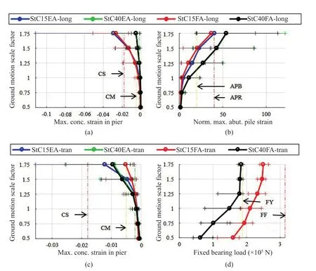
Fig. 11 Select IDA results for three-span steel IABs in the longitudinal ((a) and (b)) and transverse ((c) and (d)) directions
5.5 Four-span concrete IAB results
The most significant result of the four-span concrete IAB IDA is the relation between pier height and pier strain. As shown in Figs. 12(b) and 12(d), the IAB with shorter piers (ClC15EA) experiences much larger strains in the pier column concrete than the IAB with taller piers in both the longitudinal and transverse directions. The IAB with the taller piers rarely reaches the severe concrete damage limit state (indicated by vertical line CS), however the IAB with the shorter piers experiences it at lower than design-level scale factors. This difference in pier behavior depending on pier height can once again be attributed to shorter, stiffer piers increasing the demand in the piers. However, the additional flexibility of the long span bridge also increases the demand in the piers relative to three-span bridges due to the abutments being further away and more seismic force being loaded through the piers.
Similarly, the IAB with shorter piers experiences moderate pier concrete damage (indicated by vertical line CM), which corresponds to pier concrete spalling, at nearly all scale factor levels while the IAB with taller piers only begins to significantly experience it at the design-level scale factor of 1.00 in the longitudinal direction. The occurrence of concrete spalling correlates well with the total base shear of the bridge reaching a limit, as shown in Fig. 12(a), and the backfill load reaching a limit before mobilization, as shown in Fig. 12(c). This implies that spalling of the pier concrete is a key fusing mechanism in the longitudinal direction seismic behavior of four-span concrete IABs.
In the transverse direction, it is shown that IABs with taller piers cause larger forces and strains on the abutment through the increased abutment pile strains in Fig. 12(e). This observation, along with the observations concerning pier strain, are again attributed to the relative stiffness difference between the abutments and piers in IABs of different pier heights. Figure 12(e) also demonstrates that yielding of the abutment piles (normalized pile strain of 1.0) occurs at low scale factors, well below the design-level.
As was the case with three-span steel IABs, it was found in four-span concrete IABs that the occurrence of concrete spalling in transverse IDAs relates well with the load transferred through side retainers reaching a limit. This is shown in Fig. 12(f) where IABs with short piers experience more load transferred from the superstructure to the piers, however the spalling of pier concrete occurs before retainer fusing in both IABs. This indicates that the actual fusing mechanism in the longitudinal direction is the piers as opposed to the more desirable side retainers.

Fig. 12 Select IDA results for four-span concrete IABs in the longitudinal ((a), (b), and (c)) and transverse ((d), (e), and (f)) directions

Fig. 13 Select IDA results for four-span steel IABs in the longitudinal ((a) and (b)) and transverse ((c), (d), and (e)) directions
5.6 Four-span steel IAB results
Similar to the observations for all the other multispan IABs, it is shown that there is more pier force and strain in four-span steel IABs with shorter piers, as shown in Figs. 13(a) and 13(c), and more abutment pile force and strain with taller piers, as shown in Figs. 13(b) and 13(d). This is due to the relative stiffness of the abutments and piers depending on the pier height.
Comparing longitudinal and transverse results to each other, the mobilization of soil surrounding the piles and the strain within the piles is found to be larger in the longitudinal direction than in the transverse direction, which can be seen by comparing the x-axis scales in Figs. 13(b) and 13(d). This leads to the longitudinal analyses experiencing more abutment pile local buckling and rupture (APB and APR, respectively) than in the transverse analyses. This is due to the high flexibility of the four-span IAB in the transverse direction redistributing more load to the piers than the abutments, while the longitudinal analyses are mostly unaffected by bridge length, which can further be confirmed by the larger median concrete pier strain IDA results in Fig. 13(c) over Fig. 13(a). Overall, the transverse analyses indicate more severe pier damage and less abutment pile damage in the transverse direction than the longitudinal direction.
The increased pier strains in the transverse direction lead to concrete spalling (CM line in Fig. 13(c)) at lower scale factors, which then limits the amount of load transferred to the piers from the superstructure. This is shown in Fig. 13(e), where the transverse load transferred through the fixed bearing does not significantly vary at any scale factor and is well below fixed bearing yielding due to pier concrete spalling acting as the fuse for the piers.
5.7 General observations and discussion
A common observation throughout the IDAs in both directions for all the IABs is the relation between pier height and pier strain, side retainer or fixed bearing force, and abutment pile strain. This is due to piers with increased stiffness (i.e., shorter piers) increasing the force distributed to the piers, and therefore through the bearings and/or retainers, and decreasing the amount of force in the abutments. The opposite is true of more flexible piers, which have decreased forces in the piers and through the fixed bearings or retainers but increased forces in the abutments. It can also be observed that there is more damage and strain in the piers and abutments of concrete IABs as opposed to steel IABs. This is due to the increased mass of the concrete superstructure causing more inertial forces in the dynamic analysis; increased loads in all components lead to more IAB damage when subjected to earthquakes in both directions.
Overall, it is shown that damage is primarily in the side retainers or fixed bearings, piers, or abutment foundations. Ideally, the side retainers or fixed bearings would be the fusing mechanism in the system under transverse excitation, as they are easy to inspect and replace. Failure of the retainers or fixed bearings is also desirable in order to change the stiffness of the structure and dissipate more energy, as seen in Fig. 14, which occurred in the CtC15EA IAB at design-level excitation. While these limit states are found to occur frequently in IABs with three-spans and shorter piers due to the increased stiffness of the pier drawing force through the bearings and retainers, they often do not occur at the design-level.
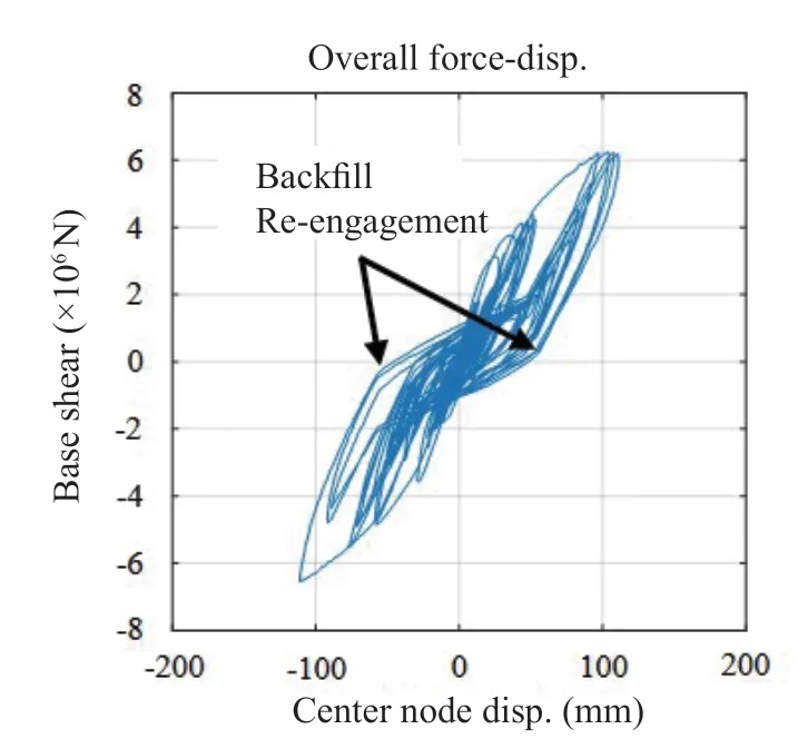
Fig. 15 Effect of backfill re-engagement on an IAB force- displacement plot
In most other IABs with more flexible piers, the fuse under design-level hazard tends to be at another location such as in the columns due to moderate damage and concrete spalling or in the abutment piles in the form of yielding, local buckling, or rupture. While concrete spalling and damage to the columns in an inspectable location is acceptable under AASHTO earthquakeresisting system (ERS) requirements (AASHTO, 2011), damage to the abutment piles is undesirable due to their difficulty for inspection and replacement.
Damage to the abutment piles is a frequent occurrence in all IABs analyzed, consistently occurring well below the design-level earthquake at the lowest ground motion scale factor of 0.5. As stated above, abutment damage is much less desirable than damage to inspectable areas such as to the piers or even to the backfill behind the abutments. When subjected to excitation in the longitudinal direction results show that the engagement and re-engagement of the backfill aids in dissipating energy, as can be observed in the overall force vs. center node displacement figure for StC15EA at the design-level shown in Fig. 15. In terms of seismic collapse through the occurrence of unacceptable limit states, it is found that concrete IABs and IABs with shorter piers are more vulnerable to collapse at lower hazard levels when subjected to earthquakes in both directions. Although IABs with long spans are vulnerable to collapse at lower seismic hazard levels in both directions, they are found to be particularly ineffective in the transverse direction due to the high flexibility of the superstructure. This can be observed through Table 3, which summarizes the ground motion scale factor at which the first occurrence of an unacceptable limit state (severe pier column damage, SS or CS, or abutment pile rupture, APR) occurs in any analysis. With the exception of the four-span concrete IABs, these limit states do not occur before the design-level scale factor of 1.00, though some are at the design-level. The fact that the unacceptable limit states are so close to the design-level event is a cause for concern. Severe damage to the piers not only affects the pier components themselves, but also adversely affects the bridge behavior as a whole in some cases by introducing a permanent offset, as seen in the center node displacement vs. time graph for a designlevel ground motion time history on the CtC15EA bridge in Fig. 16.

Table 3 Ground motion scale factor of the first occurrence of either the SS, CS, or APR limit state

Fig. 16 Demonstration of permanent offset due to severe pier damage
6 Conclusions
Through analyzing a variety of limit states affecting different components of IABs with varying bridge parameters, a few main conclusions can be made from the pushover and incremental dynamic analyses performed on comprehensive IAB models. These observations would not have been possible by simply analyzing the components and limit states individually―by analyzing the IABs at the system-level, interactions between the components were able to be observed. The concluding observations are summarized as follows:
• Moderate pier concrete damage, which is associated with pier concrete spalling, often corresponds to the peak load carrying capacity of an IAB. This indicates that pier damage acts as a fuse for the bridge, which is acceptable under AASHTO ERS requirements; however, it is more desirable to have fusing occur between the piers and superstructure in the form of side retainer or fixed bearing fusing.
• Consistent foundation abutment damage in the form of the abutment piles yielding, buckling locally, or rupturing occurs in almost all IAB analyses in both ground motion excitation directions (transverse and longitudinal). This is concerning due to the difficulty to inspect and replace these components.
• There is a trade-off between abutment foundation damage and pier column damage depending on the stiffness of the piers. Taller flexible piers concentrate more damage in the abutments, while shorter and stiffer piers concentrate more damage in the piers.
• IABs with concrete superstructures experience more damage than IABs with steel superstructures when subjected to ground motions in any direction. This is due to the increased mass of concrete superstructures, which can be approximately 65% heavier than steel superstructures for the same spans.
• Seismic collapse due to severe column damage is more common in IABs with concrete superstructures, IABs with shorter piers, and IABs with longer spans. Long-span concrete IABs are particularly susceptible to collapse at seismic hazard levels less than the AASHTO design-level.
These conclusions have been used to assess IABs of varying parameters under seismic loads and lead to a series of design implications and recommendations that can be utilized to minimize undesirable IAB seismic behavior. These implications and recommendations can be valuable to bridge designers for various seismic regions, including southern Illinois; they are as follows:
(1) Bearings, retainers, and columns should be designed as a system. It is more desirable to replace the side retainers or fixed bearings of a bridge than entire piers, and they are both easy to inspect after an event. In this regard, the columns, bearings, and retainers should be analyzed and assessed as a system to ensure that the retainers or fixed bearings fuse before spalling in the pier columns.
(2) Flexible (i.e., longer and/or heavier) IABs require more robust columns. This should be considered due to the increased force demands placed on the piers in the four-span concrete IABs under transverse excitation. This IAB, along with other heavier IABs such as concrete IABs, places considerably larger loads on the pier columns, which should be taken into account. In addition to this suggestion, caution should be used when designing a long-span, heavy IAB in general due to the increased forces in all components.
(3) IAB use in southern Illinois should be limited to steel girders instead of PPC girders. While PPC girders may be used for some cases, they should only be considered for use in IABs with total spans of 85 m (280 ft) or less. Longer span IABs should utilize steel girders.
(4) Backfill contributions may be increased. The consistent damage to the abutment piles is undesirable, as it is more desirable to instead mobilize the backfill or dissipate greater energy through the soil and less through the piles. In order to do this, the backfill contribution to longitudinal resistance could be increased through methods such as increasing the contact area of the abutment, increasing the strength and stiffness of the backfill through mechanical stabilization, or including additional material layers to aid in dissipating energy.
Acknowledgement
This paper is based on the results of ICT R27-133,Calibration and Refinement of Illinois’ Earthquake Resisting System Bridge Design Methodology: Phase II. ICT R27-133 was conducted in cooperation with the Illinois Center for Transportation (ICT); Illinois Department of Transportation (IDOT); and the U.S. Department of Transportation, Federal Highway Administration (FHWA). This work used the Extreme Science and Engineering Discovery Environment (XSEDE), which is supported by National Science Foundation (NSF) Grant No. ACI-1548562. The contents of this paper reflect the view of the authors, who are responsible for the facts and the accuracy of the data presented herein. The contents do not necessarily reflect the official views or policies of the ICT, IDOT, FHWA or NSF.
杂志排行

Earthquake Engineering and Engineering Vibration的其它文章
- Dynamic shear modulus and damping ratio characteristics of undisturbed marine soils in the Bohai Sea, China
- Geotechnical engineering blasting: a new modal aliasing cancellation methodology of vibration signal de-noising
- Response prediction using the PC-NARX model for SDOF systems with degradation and parametric uncertainties
- Probability-based analytical model for predicting the post-earthquake residual deformation of SDOF systems
- Seismic behavior of multiple reinforcement, high-strength concrete columns: experimental and theoretical analysis
- Numerical study of a multiple post-tensioned rocking wall-frame system for seismic resilient precast concrete buildings