Numerical study of a multiple post-tensioned rocking wall-frame system for seismic resilient precast concrete buildings
2022-04-15AfshinNaserpourandMojtabaFathi
Afshin Naserpour and Mojtaba Fathi
Department of Civil Engineering, Engineering Faculty, Razi University, Kermanshah 6714665989, Iran
Abstract: A multiple rocking wall-frame (MRWF) system, in which the wall panels are directly connected to the adjacent beams and foundation is presented herein. In the MRWF system, the unbonded post-tensioned (PT) tendons are used to promote the self-centering ability, and O-shaped steel dampers are applied to enhance the energy dissipation capacity and reparability of the structure. First, analytical equations are proposed to determine the behavior of the O-shaped dampers. Then, the MRWF system is numerically evaluated for five different models consisting of rocking walls with varying numbers and arrangements while keeping the total effective width of wall panels constant. The numerical results show that with an increase in the number of wall panels and a decrease in the wall width, the hysteretic behavior of the MRWF system tends to the ideal flag-shaped pattern, resulting in little damage to the beams, insignificant strain in the wall toe, negligible residual drifts and damage index of less than 0.2 under severe earthquakes. In contrast, the conventional model demonstrates extensive damage to the structural elements due to undesirable wall-to-frame interaction, which leads to a damage index of 0.78 and residual drifts of 0.42% under seismic loads.
Keywords: precast wall-frame system; rocking behavior; post-tensioning; O-shaped steel damper; residual drift
1 Introduction
Past major earthquakes have revealed that reinforced concrete (RC) buildings designed based on the current design philosophy suffer significant structural damage. In fact, by allowing for formation of plastic hinges, irreparable damage is inflicted on the members of the structure, which may result in large residual displacements, and repair costs, and in some cases, demolition (Kamet al., 2011; Pampaninet al., 2011; Wadaet al., 2018; Xuet al., 2020).
Due to these deficiencies, it is necessary to develop low-damage systems which can withstand severe earthquakes with minimal structural damage. Indeed, in such systems, instead of plastic hinge formation in the structural elements, the rocking mechanism is performed at the connection joints, called ductile joints. At the ductile joints, the elements are connected to each other using unbonded post-tensioned (PT) tendons which provide the self-centering ability and reduce the residual displacements.
To enhance the energy dissipation capacity, the replaceable energy dissipating devices such as friction and yielding steel dampers are applied. These dampers are activated through rocking mechanism in the connection joints such as the wall-to-foundation and the beam-to-column interfaces (Mao and Wang, 2021).
The precast seismic structural systems (PRESSS) project (Priestleyet al., 1999) was the first study conducted on low-damage lateral resisting systems. During the PRESSS project, a jointed rocking wall system consisting of two unbonded PT rocking walls was investigated. Unbonded PT tendons were implemented to improve the self-centering ability and diminish story residual drifts. In addition, a series of U-shaped steel connectors were attached to the vertical joint between the wall panels to enhance the energy dissipation capacity. Due to the rocking behavior, the U-shaped steel connectors underwent flexural deformation through the relative displacement between the walls. To improve the reparability of the jointed wall system, Guoet al. (2018) experimentally studied a self-centering wall system. In this system, the friction connectors were applied instead of using mild steel connectors, and the steel jackets were placed at the corners of the wall panels to prevent the concrete crushing.
As an alternative to the jointed wall system, other self-centering rocking wall systems have been developed. Kuramaet al. (1999) analytically proposed the hybrid wall system which included a single rocking wall panel in which a series of mild steel bars were placed internally at the wall-to-foundation interfaces. In recent years, many researchers have investigated the cyclic and seismic behavior of hybrid wall systems (Restrepo and Rahman, 2007; Perezet al., 2007; Guet al., 2019; Smith and Kurama, 2014). In addition, a shake table test has been carried out on a five-story precast concrete building with a hybrid wall system (Luet al., 2018).
One of the main purposes of low-damage systems is to be repairable and replaceable after extreme earthquakes. However, it is difficult to inspect and repair the hybrid wall system in which mild steel bars are used internally. To enhance the reparability of the hybrid wall systems, tension-compression yielding steel dampers and viscous dampers with external attachment to the rocking wall have been considered as the effective solutions (Marriot, 2009).
In order to improve the lateral stiffness and strength of the jointed wall system, Sritharanet al. (2015) introduced the precast rocking walls with two end columns (PreWEC) system. The PreWEC system is comprised of a PT wall which is connected to two end columns through oval-shaped steel connectors. The most important motivation for applying the oval-shaped connectors is that they can be easily manufactured and replaced after severe earthquakes. Aaleti and Sritharan (2011) experimentally ascertained that the PreWEC system has a lateral strength comparable to conventional shear wall systems with the same geometry dimensions. In recent years, more experimental studies have been carried out on the cyclic and dynamic behavior of the PreWEC system (Twigdenet al., 2017; Twigden, 2016; Nazari, 2016; Twigden and Henry, 2019).
Overall, based on the above-mentioned studies, it can be concluded that unbonded PT rocking walls combined with supplementary energy dissipaters exhibit an ideal flag-shaped hysteretic behavior, demonstrating the self-centering ability and favorable energy dissipation capacity. However, past studies have mostly focused on the isolated rocking wall systems in which the rocking mechanism is only performed at the wall-to-foundation joint, leading to some challenges and inconveniences.
Due to the rocking mechanism, wall uplift has occurred, which resulted in local damage to the floors connected to the wall. Special shear connectors which transfer the shear load while allowing vertical displacement can be adopted to connect the rocking wall panels to the floor diaphragms (Watkins, 2017). However, other alternative approaches should be considered to transfer the gravity loads while minimizing the local damage to the floor diaphragms.
Although the isolated rocking wall systems have the advantage of superior seismic performance and the self-centering ability, the interaction of wall-to-frame can significantly influence the wall responses (Waugh and Sritharan, 2010). In other words, undesirable wall-to-frame interaction can result in local damage to the primary structural elements and diminish the selfcentering ability (Naserpour and Fathi, 2021).
The current study investigates a rocking wallframe system in which several multiple rocking walls are directly connected to the adjacent beams using PT tendons. The proposed system is intended to address the current challenges of the isolated rocking wall system. Furthere details about the proposed system are presented herein.
2 Proposed multiple PT rocking wall-frame system
2.1 Concept of proposed system
In this section, a multiple rocking wall-frame (MRWF) system is proposed. Figure 1 shows the details of the MRWF system. The system includes the following structural details: (1) Rocking wall panels within a single span of frame. These wall panels have rocking interfaces at both the two ends and are directly connected to the surrounding frame using unbonded PT tendons. Note that the wall panels can be arranged regularly or irregularly along the elevation to mitigate the undesirable effects of wall-to-frame interactions. (2) O-shaped steel dampers which are applied to the corners of the rocking walls. (3) Simple connection of the beam-to-column with a seated steel angle. (4) Simple connection of the column-tofoundation with steel angles.
Figure 1(b) shows further details of the O-shaped steel dampers. Each damper consists of several O-shaped steel connecters which are welded to two supporting steel plates at the top and the bottom. Note that the O-shaped steel dampers have been adopted from the curved-dampers (Hsu and Halim, 2018) and archdampers (Leeet al., 2018). These types of steel dampers exhibit plastic deformation without any premature failure and instability due to their flexural behavior. In other words, the circular type elements can significantly reduce the effects of stress concentration which leads to a large deformation ability for the steel dampers. In addition to the superior energy dissipation capacity, the O-shaped dampers are simply constructed from steel plates which results in lower initial costs. Note that by attaching the O-shaped steel dampers to the corners of the rocking walls, concrete crushing can be mitigated and each wall is used individually, leading to a better arrangement of the wall panels. On the contrary, when the shear connectors are used for improving the energy dissipation capacity, jointed wall systems are required in which the wall panels are next to each other to allow for placement of the shear connectors along the vertical joints.
Figure 1(c) presents the details of the beam-tocolumn connection. In the connection, a seated steel angle is utilized which may have stiffeners to increase the shear load capacity. Note that a top steel angle is placed on the top of the beam, and then a part of it is welded to the column. This connection is expected to be semi-rigid due to using the stiffeners and the top steel angle.
Figure 1(d) shows the details of the column-tofoundation connection. In this connection, the applied shear resistant steel angles are bolted to the foundation and welded to the column.
Given the above-mentioned configurations for the proposed system, the following advanatges are expected to be achieved:
- The need to implement special shear connectors for wall-to-floor connections can be eliminated.
- The O-dampers are used externally to be removable, replaceable, and accessible for inspection.
- Self-centering ability is provided using unbonded PT tendons.
- The system has the potential to be applied for seismic retrofitting purposes.
2.2 Proposed analytical equations for structural behavior of the O-shaped dampers
Analytical equations are proposed in this section to determine the structural behavior of the O-shaped steel dampers under vertical loading. Then, the performance of the O-shaped damper is evaluated by analytical and numerical analyses.
Figure 2(a) shows an O-shaped connector under vertical loading ofF. Due to this vertical loading, maximum coupling of the bending moment (MO) will be developed in pointO(Fig. 2(a)). In addition, at pointO, there is half of the vertical loading ofF. In accordance with Fig. 2(b) and Fig. 2(c), the maximum coupling of the bending moment (MO) can be calculated by Eq. (1), which is based on the elastic energy methods.
Due to Eq. (1), the total vertical deformation (d) of the O-shaped connector under vertical loading ofFcan be expressed by Eq. (2).
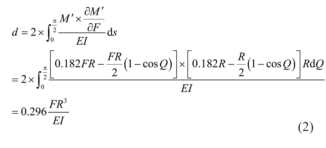
From Eq. (1) and Fig. 2(d), yield strength (Fy) and plastic strength (Fp) of the O-shaped connector can be calculated by Eq. (3) and Eq. (4), respectively.
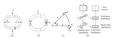
Fig. 2 (a) O-shaped connector under axial loading, (b) free-body of the O-shaped connector, (c) developed internal forces in the O-shaped connector, and (d) stress distribution in the O-shaped connector

Therefore, by substituting Eq. (3) to Eq. (2), the yield deformation of the O-shaped connectors is explained as follows:
Accordingly, the theoretical initial stiffness of the O-shaped connector can be estimated by Eq. (6).
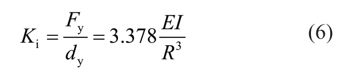
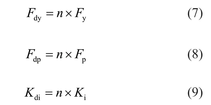
Since several O-shaped connectors with parallel arrangement are used in each damper, the yield strength (Fdy), plastic strength (Fdp) and initial stiffness (Fdi) of the damper are determined by:
It is expected that the O-shaped steel dampers reveal a strength behavior beyond the yield and plastic strengths during the cyclic loadings. Therefore, it is useful to estimate the ultimate strength (Fdu) of the O-shaped damper. To this end, according to the equation proposed by Twigden and Henry (2015), the ultimate strength of the O-shaped damper can be determined as follows:
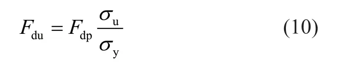
Note that is attained when the ultimate deformation is twenty times the yield deformation ofdy(20×dy) (Twigden and Henry, 2015).
In Eq. (1) to Eq. (10),Ris the median radio,Eis the modulus of elasticity,Iis the inertial moment,Sis the elastic section modulus,Zis the plastic section modulus,Ais the cross section,bis the width,tis the thickness,σyis the yield stress of material,nis the number of the O-shaped connectors, andσuis the ultimate stress of the material used for the O-shaped connectors.
Given the analytical equations, it is expected that the O-shaped dampers exhibit an axial-flexural plastic deformation under vertical loading. Past experimental studies (Hsu and Halim, 2018) have shown that the dampers having axial-flexural plastic deformation that provides stable hysteretic behavior and remarkable energy dissipation capacity if out-of-plane buckling is prevented. To avoid local buckling in the dampers, Hsu and Halim (2018) proposed the width (b) to thickness (t) ratio be smaller than 4. However, this ratio was proposed for the curved-dampers, while the O-shaped steel dampers are geometrically different from the curved-dampers. Accordingly, to evaluate the proposed analytical equations and address the suitableb/tratio for preventing local buckling, four different models of the O-shaped dampers have been studied. The characteristics of the considered O-shaped dampers are reported in Table 1. The table presents the analytical results of yield strength, plastic strength and initial stiffness of the O-shaped steel dampers. Note that the characteristics of material used in the dampers were as follows: yield stress ofσy= 360 MPa, ultimate stress ofσu= 540 MPa, and elasticity modulus ofE=2×10⁵MPa.
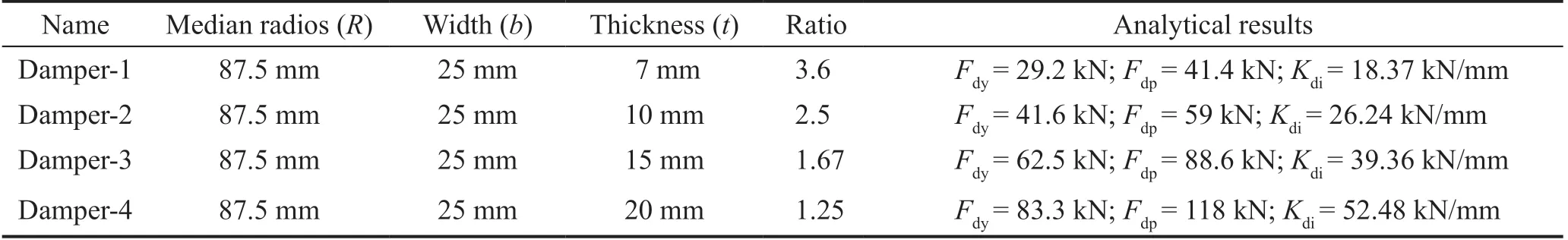
Table 1 Characteristics of the O-shaped dampers
To evaluate the performance of the O-shaped steel dampers as well as analytical equations, threedimensional finite element model (FEM) were developed in ABAQUS software (Hibbit, Karlsson and Sorensen, Inc., 2016). The modeling assumptions for the FEM of the dampers were as follows. All members, including bottom and upper supporting plates and the O-shaped connectors, were modeled via C3D8R solid element with reduced integration available in ABAQUS. The nonlinear behavior of the steel material was adopted through a plastic material with the combined isotropic and kinematic hardening. Note that to consider the buckling modes in the FE models, an imperfection based on the critical buckling mode needs to be implemented. Figure 3(a) shows meshing and boundary conditions for one of the FE models. For these FE models, a nonlinear static analysis was accomplished through a displacement-control loading as shown in Fig. 3(b).
Figure 4(a) illustrates the force-displacement results of numerical models alongside the results of analytical equations. Damper-1, which has a width/thickness ratio of 3.6, reveals the local buckling under cyclic loading, resulting in an imperfect hysteretic behavior. By decreasing the width/thickness ratio, the O-shaped dampers exhibit favorable hysteretic behavior and superior energy dissipation. Also, as shown in Fig. 4(a) the analytical equations estimate the envelop force-displacement responses of the O-shaped dampers reasonably well with theb/tratio smaller than 3.6. For example, in damper-4, maximum variations in the analytical and numerical results of the yield strength, plastic strength and initial stiffness are equal to 8.5%, 1% and 14%, respectively.
To observe the deformed shape of the O-shaped dampers, Fig. 4(b) indicates the stress distribution of the dampers under maximum compressive loading. As expected, damper-2 to damper-4 have an axial-flexural deformation under vertical loading, while in damper-1, out-of-plane buckling occurs due to higher width/thickness ratio.

Fig. 3 FE modeling of the dampers in ABAQUS
As a result, it can be stated that the O-shaped steel dampers have a stable hysteretic behavior without any stiffness and strength degradations if theb/tratio is less than 2.5.
3 Model description and analysis
To study the behavior of the MRWF system, a twostory building located on a stiff soil (site class D) in Los Angeles, California was considered. The dead loads and live loads were equal to 45 and 12 kN/m, respectively, and were directly applied to the beams. The plan of the building was a square (19 m × 19 m) with three spans in each horizontal direction. The MRWF system was located at mid-span of the peripheral frame with a length of 7 m and height of 4 m for each story. Due to the regularity of the building plan and ignoring the torsion effects, 2D frames were considered to study the behavior of the MRWF system.
These 2D models were designed in such a way to meet the requirements defined by ASCE 7-05 (2005) and IBC (2009) for the shear wall system. The models include five MRWF models with different strucutral layout and a conventional model as shown in Fig. 5(a). For the MRWF models, the numbers and arrangement of wall panels were changed while keeping the total effective width of the wall panels constant in each story.
For a fair comparison among the MRWF models, the initial post-tensioning force and damper characteristics were kept the same in each rocking wall panel. To this end, the damper-4 reported in Table 1 and initial posttensioning force of 534.8 kN were considered for all of the rocking wall panels.
Figures 5(b) and 5(c) show the design specifications for the walls and members of the frame, respectively. Note that the material properties used for elements were as follows: compressive strength of unconfined concretefc= 40 MPa, elasticity modulus of concreteEc= 32 GPa, yield strength of mild steel used for O-shaped dampersfyd= 360 MPa, elasticity modulus of mild steel used for O-shaped dampersEsd= 200 GPa, yield strength of mild steel reinforcingfyr= 400 MPa, yield strength of posttensioned tendonsfypt= 1600 MPa, elasticity modulus of post-tensioned tendonsEspt= 200 GPa, and ultimate strength of post-tensioned tendonsfupt= 1860 MPa.
The behavior of the MRWF models is considered through cyclic and time history analyses. Cyclic analyses were accomplished using the loading protocol shown in Fig. 6. This loading was a displacement control type, and its coefficients were considered for the drifts of ±0.1%, ±0.25%, ±0.5%, ±0.75%, ±1%, ±1.5%, ±2% and ±2.5%.
To carry out the nonlinear time history (NLTH) analyses, a suite of ten ground motion records related to stiff soil (type D) were selected from the PEER ground motion database (2016). The characteristics of the selected ground motion records are shown in Table 2. These records were scaled for two intensity levels of design basis earthquakes (DBE) and maximum considered earthquakes (MCE), representing 10% and 2% probabilities of exceedance in 50 years, respectively. Accordingly, the earthquake records were linearly scaled in such way that their average pseudo-acceleration spectra closely matched with the target spectra of the ASCE 07-05 over the period rage of interest in this study (0.3 s to 2 s). The selected period range should take into account all expected periods in which the structure is sensitive to respond nonlinearly. Figure 7 compares the target spectra with those of the scaled records. It is clear from Fig. 7 that the average spectra of scaled records are in a good agreement with the target spectra.
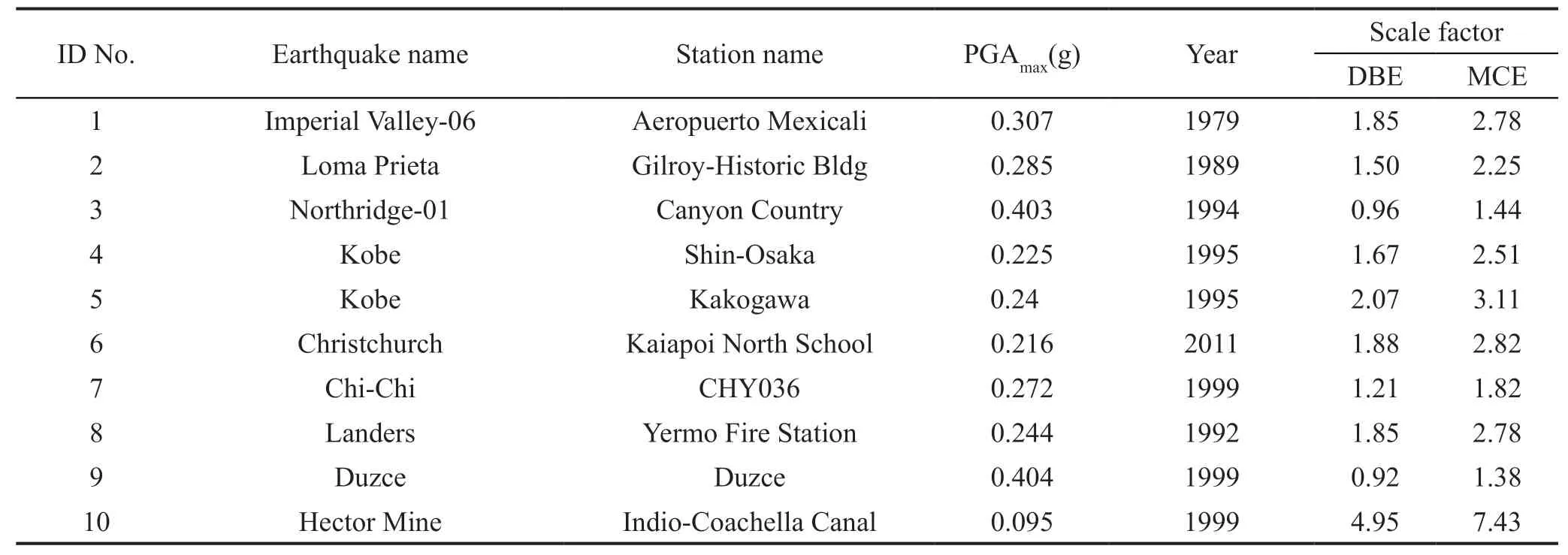
Table 2 Earthquake records and scaling
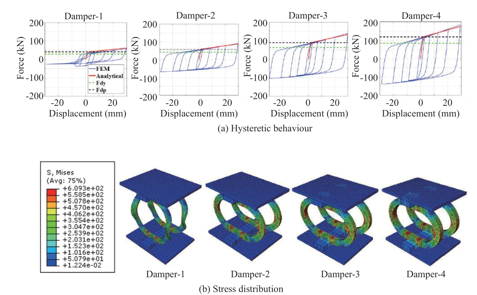
Fig. 4 Results of the O-shaped dampers
Note that a lumped seismic mass of 135 t was assigned to each story due to the tributary area of each wall, and an equivalent linear viscous damping of 5% was adopted for first three modes of vibration.
4 Numerical models
4.1 FE model development
To study the performance of the MRWF models, two types of numerical models were developed. 3D FE models were developed using ABAQUS software to show more details and more rigorous results under pushover loading. In developing the FE models of ABAQUS, solid element (C3D8R element) was used to model the beams, columns and walls. For each confined and unconfined section of the concrete, the nonlinear stress-strain values shown in Fig. 8 were used. These values were considered according to the equations provided by Chang and Mander (1994) for both the compressive and tensile properties of the concrete.
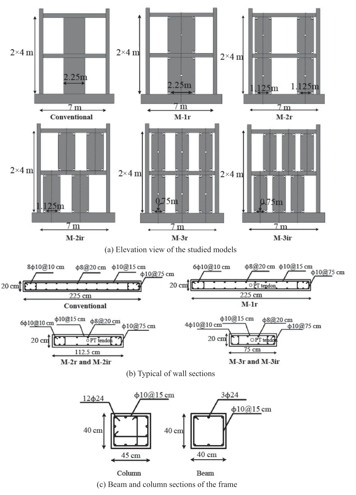
Fig. 5 Configurations of the considered models
The damaged plasticity concrete material available in ABAQUS was used to consider the nonlinear behavior of concrete. Truss element was applied for each of the reinforcing bars as well as post-tensioned tendons. The reinforcing bars were embedded in each of the solid elements of the beams and columns. The nonlinear properties of the materials used in the longitudinal reinforcement and the post-tensioned tendons are shown in Fig. 8. Note that the steel angles were modeled through the modeling assumptions described in Section 2.2 and used for the FE model of the dampers. After defining the elements and materials, the models were assembled and meshed as shown in Fig. 9.

Fig. 6 Time history of imposed cyclic loading (ITG 5.1-07, 2007)
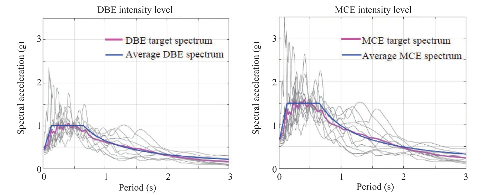
Fig. 7 Earthquake and target response spectral scaled for DBE and MCE intensity levels
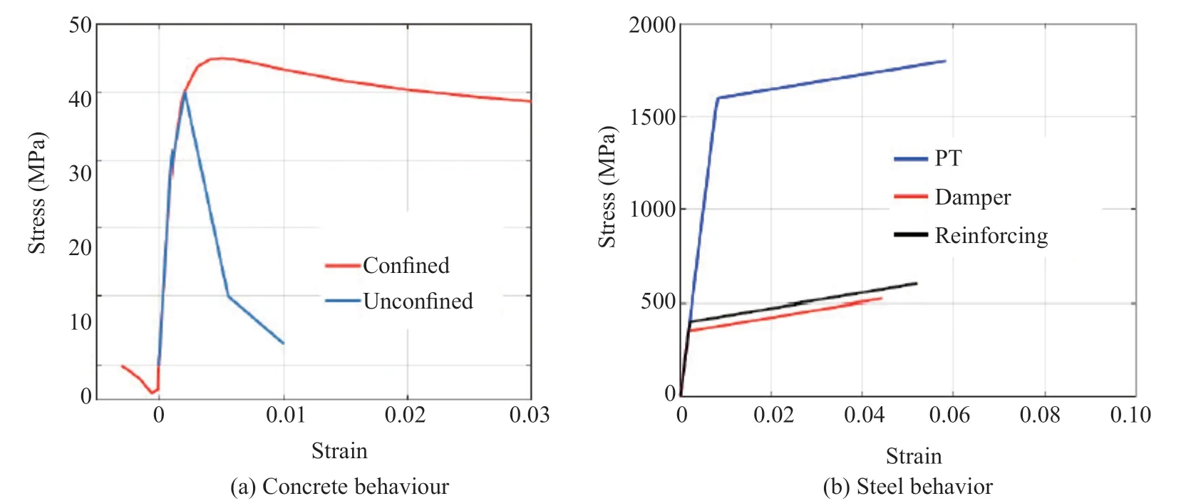
Fig. 8 Definition of material for FEM developed in ABAQUS
The rocking mechanism between the wall and beam/foundation interfaces was defined through surface to surface contact interaction, which provided hard contact while allowing the gap opening in the normal direction and implemented a friction mechanism using the penalty method with a coefficient factor of 0.5 (Stanton and Nakaki, 2002) in the tangential direction.
Steel angles, used for beam-to-column and columnto-foundation connections, were tied to each element in accordance with the weld lines. Additionally, the bolts used in the connection of the column-to-foundation were modeled using solid element (see Fig. 9). These bolts were embedded to the foundation and interacted to the steel angles by means of the surface to surface interaction.
To consider post-tensioning forces in the tendons, each tendon element was initially subjected to a stress using predefined loading, and the lower and upper part of each tendon was restricted in the vertical direction. Then, in the first step, the restraints considered in the tendons were removed to introduce pre-compression forces into the walls (Henry, 2011). For modeling the anchorage of PT tendons, two rigid elements tied to the beam elements were coupled in the vertical and horizontal directions to the top and bottom of the tendons. Because the wall panels are directly connected to the beams, it is rational to assume that the wall panels carry a part of the gravity loads. Therefore, in addition to the columns, some vertical load was applied to the wall panels to consider the gravity loads. After accomplishing the first step of analysis, the second step was considered. In this step, the roof and first story were subjected to a displacement control lateral load based on the inverted triangular loading pattern. In this situation, to diminish the running time of analysis, just one complete cycle of the lateral loading at the story drift of 2.5% was considered.
To carry out the complete cyclic and nonlinear time history (NLTH) analyses, the fiber based FE model developed in OpenSEES was used (Mazzoniet al., 2013). Using the fiber based FE models, the running time of the analyses are appreciably reduced, especially for the NLTH analyses. In the MRWF models conducted in OpenSEES, columns, beams and walls were accomplished using displacement-based beam-column elements with fiber sections. Note that due to the extensive damage that will be occurred in the plastic hinge regions of conventional shear walls, the force-based beam-column element was preferred to capture the spread plasticity along the length of the members. The truss element was considered to model the PT tendons, and steel01 material with initial strain was assigned for the truss element to address the posttensioning force. For simulating the gap opening and closing of connections (rocking behavior), wall-to-beam interfaces were modeled by zero-length contact element with zero-tensile stress material (ENT material). The value of the compressive stiffness for the ENT material was 10 times the axial stiffness of the rocking wall panels. Note that in each of the interfaces, a zero-length horizontal spring element was performed to prevent slipping of the wall panels. Also, the O-shaped dampers were modeled by spring elements with steel02 material. These O-shaped dampers were connected to the wall panels using stiff elastic beam-column elements. The modeling assumptions of OpenSEES FE models are shown in Fig. 10.
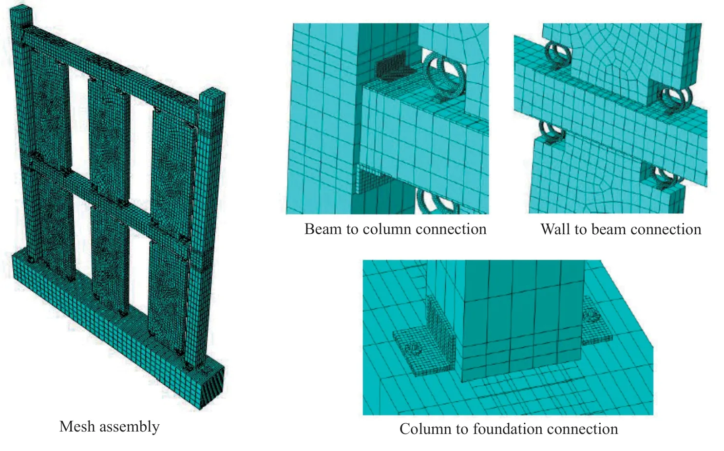
Fig. 9 FE model of MRWF system by ABAQUS (2016)
4.2 Verification of FE models
To validate the modeling assumptions considered for the FE models, the PreWEC system test performed by Twigdenet al. (2017) was utilized (see Fig. 11). The PreWEC system was selected because of its similar behavior to the MRWF system. In the experimental test proposed by Twigdenet al. (2017), a PreWEC system known as PreWEC-A was subjected to quasi-static cyclic loading.
The design specifications of the test model include: wall height of 2860 mm, wall length of 800 mm, wall thickness of 125 mm, four oval-shaped steel connectors attached to each vertical joint between the wall and the column and post-tensioning force of 300 kN at each wall. More details about the test set up can be found in Twigdenet al. (2017).
According to the modeling assumptions given in the previous section, two FE models were accomplished for this experimental model. Note that in the FE model of OpenSEES, the oval-shaped connectors were modeled by the vertical spring elements with the steel02 material. The mechanical characteristics of the oval-shaped connectors were considered in accordance with the analytical equations proposed by Twigden and Henry (2015).
Figure 12 shows the deformed shape and stress contours at 3% drift for the ABAQUS FE model. It is observed that the numerical model properly illustrates the rocking mechanism at the base of the wall and indicates the flexural deformation for the oval-shaped steel connectors.
In Fig. 13(a), the force-displacement results of the numerical models are compared with those of the experimental model. There is a good agreement between the numerical and experimental results of force-displacement. Also, as expected, the hysteretic behaviors of the numerical models are close to the ideal flag-shaped curve which is the main characteristic of the rocking systems.
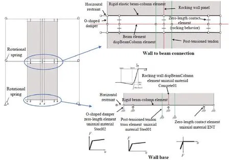
Fig. 10 Fiber based FE model developed in OpenSEES
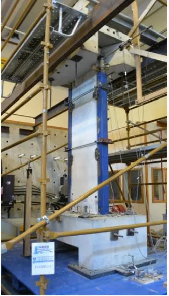
Fig. 11 Test set up (Twigden, 2016)
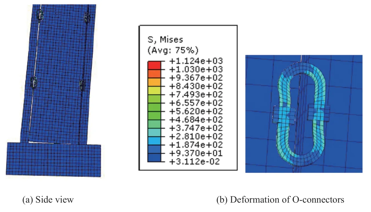
Fig. 12 FEM of PreWEC-A at 3% lateral drift
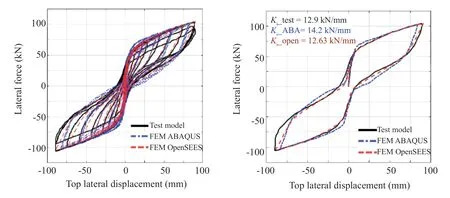
Fig. 13 Hysteretic behavior response of PreWEC-A (Twigden, 2016)
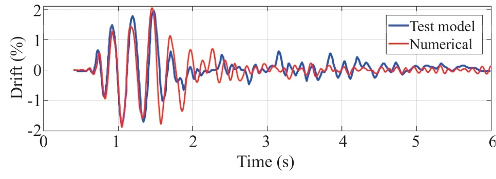
Fig. 14 Drift time history for PreWEC-ST-A subjected to EQ-VI: GM2
Figure 13(b) presents backbone curves (envelope response of cyclic curves) for all models. According to the figure, initial lateral stiffness associated with the ABAQUS and OpenSEES FE models are 14 kN/mm and 12.6 kN/mm, respectively. These values are close to the value of 12.9 kN/mm of the test model. Also, the enclosed area of the backbone curve of the ABAQUS and OpenSEES FE models are equal to 9271 kN.m and 8382 kN.m, respectively, which are close enough to the experimental result.
Because the OpenSEES models were developed to carry out the dynamic analyses, it is useful to validate the modeling assumptions with a dynamic test model. To this end, the dynamic test of PreWEC-ST-A (Twigden, 2016) was simulated by OpenSEES software. In the dynamic test model of PreWEC-ST-A, the effective mass was equal to 3.93 t, and earthquake records were scaled based on the similitude law for shake-table testing. Also, the records were scaled in such way to satisfy the velocity limit of the shake-table and to be compatible with the design spectrum. Further details about the dynamic test of PreWEC-ST-A can be founded in Twigden (2016).
By carrying out the modal analysis, it was found that the fixed base period of the FE model was equal to 0.0966 s, which closely matched with the fixed base period of 0.096 s related to the test model. During the dynamic testing, it was observed that the inherent damping ratio of PreWEC-ST-A was equal to 3.11 % (Twigden, 2016). Accordingly, this value was considered for the dynamic analysis of the FE model of PreWECST-A. To evaluate the seismic behavior of the numerical model, the EQ-VI: GM2 record of the shake-table test (Twigden, 2016) was applied. Figure 14 shows the drift time history response. Compared to the test result, the numerical model estimates the drift time history response reasonably well. The peak drift of the test and numerical models are equal to 1.97% and 2.06%, respectively. Consequently, the developed FE models are appropriate for estimating the behavior of the rocking wall systems.
5 Results
5.1 Cyclic results
The maximum strain distribution at a roof drift of 2.5% is presented in Fig. 15. For the conventional model, the formation of plastic hinges at the base of the shear wall leads to extensive structural damage. In addition, due to the undesirable wall-to-frame interaction, local damage occurred in the beams of the conventional model.
For the MRWF models, M-1r and M-2r, which have a lower number of wall panels with larger width, exhibited unfavorable wall-to-frame interaction which led to local damage in the beams. On the contrary, by increasing the wall panel numbers and decreasing the wall width, the lower force demands are transferred from the wall panels to the beams, resulting in more favorable wall-toframe interaction and minimal structural damage to the frame elements.
For a rocking wall system, it is very important to control the concrete damage that occurred in the wall toe due to the wall uplift. Experimental studies (Henry, 2011) have revealed that the cyclic residual displacements increase when the corners of the wall panels undergo local damage. In this situation, the reparability of the system may be alleviated and an imperfect flag-shaped hysteretic behavior occurs. To investigate the behavior of the concrete on the corners of the walls, maximum strain results at the wall base of the ABAQUS FE models are presented in Fig. 16. According to Fig. 16(a), by applying the O-shaped dampers at the corners of the wall panels as well as by decreasing the wall width, the maximum strain in the wall toe is significantly decreased. To further study the behavior of the wall toe, the extracted backbones of maximum compressive strain in the corners of the wall panels associated with the MRWF models are shown in Fig. 16(b). Also, for additional comparisons, the ultimate confined concrete strain (εcc) and the ultimate unconfined concrete strain (εcu) are presented in Fig. 16(b). For calculating theεcc, Manderet al. (1988) proposed Eq. (11).
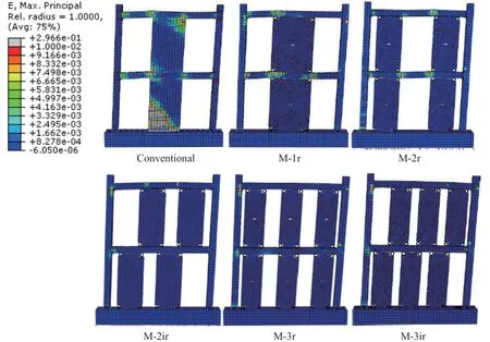
Fig. 15 Maximum strain distribution at the roof drift of 2.5%

Fig. 16 Strain state on concrete of the wall panels of MRWF models
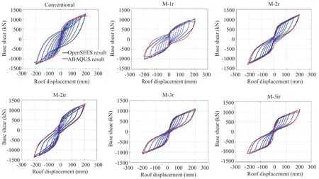
Fig. 17 Hysteretic behavior of models
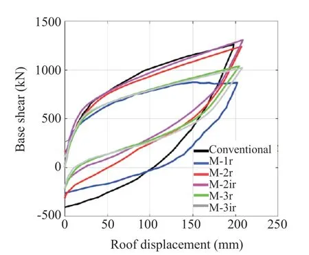
Fig. 18 Back-bone curves
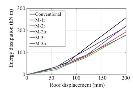
Fig. 19 Energy dissipation results
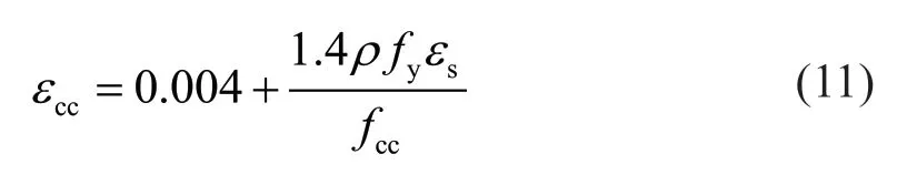
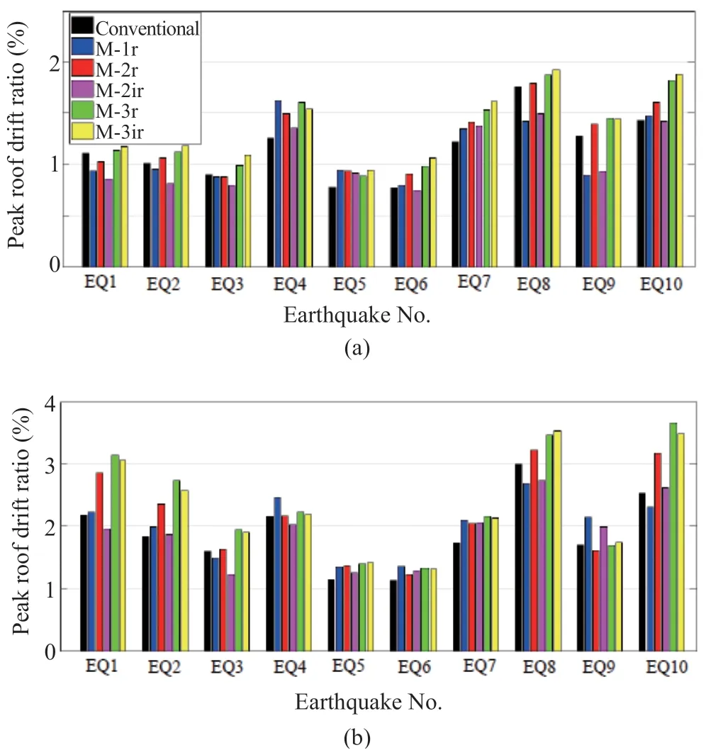
Fig. 20 Peak roof drift ratio: (a) DBE events (b) MCE events
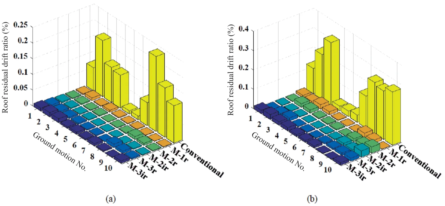
Fig. 21 Residual drift ratio in the roof: (a) DBE events (b) MCE events
wherefccis the confined compressive strength of concrete,ρis the transverse steel ratio at the confined region,fyis the yield stress of steel, andεsis the steel strain at the maximum tensile stress.
Figure 16(b) shows that the M-1r model has the compressive concrete strain beyond the ultimate confined concrete strain in the wall toe, leading to concrete crushing. Conversely, by decreasing the wall width, the compressive concrete strain is significantly decreased. Thus, the M-3r and M-3ir exhibit much less maximum compressive strain than the ultimate unconfined concrete strain, and most of the stresses and strains are concentrated in the O-shaped steel dampers.
Figure 17 shows the hysteretic behavior of models under cyclic loading. It is observed that M-2r to M-3ir models have a flag-shaped hysteretic behavior, while the M-1 model has an imperfect flag-shaped hysteretic behavior due to the damage that occurred in the beams and walls. Also, for the conventional model, the pinching phenomena is observed in the hysteretic behavior due to the formation of plastic hinges and local damage to the primary structural elements.
Note that the results of the OpenSEES models are satisfactorily close to the force-displacement results of the ABAQUS models.
Figure 18 compares the backbone curves of the models. The initial lateral stiffness is almost identical for all models. However, the lateral strength of M-2r, M-2ir and conventional model are slightly higher than that of the other models. In contrast, the cyclic residual displacement of the M-3r and M-3ir are less than that of the other models. These results affirm that by increasing the wall panel numbers and decreasing the wall width, the self-centering ability is improved.
Figure 19 shows the energy dissipation in each cycle for the models. The energy dissipation in each cycle refers to the enclosed area of the force-displacement results in that cycle. In general, the conventional model shows higher energy dissipations than the MRWF models. The maximum variation of energy dissipation between the conventional and MRWF results is about 30%. Overall, as the number of wall panels increases, the energy dissipation decreases due to the slight damage and greater self-centering ability.
5.2 Time history results
In this section, a series of dynamic analyses were conducted to evaluate the seismic behavior of MRWF models compared to a conventional model. Note that similar to the cyclic analyses, a part of the gravity loads was applied to the wall panels of the numerical models developed for dynamic analyses.
The results of peak roof drift ratio for all models are shown in Fig. 20 for two intensity levels of DBE and MCE. The roof drift ratio is defined here as the roof displacement divided by the frame height. As shown in Fig. 20, for many cases, the roof drift ratios of the conventional model are slightly lower than those of the other models. However, none of the models reveal a peak roof drift ratio higher than the allowable limited drifts of 2.5% and 3.75% for DBE and MCE events (IBC, 2009; NZS 1170.5, 2004), respectively. For DBE events, the maximum peak roof drift ratio for conventional, M-1r, M-2r, M-2ir, M-3r and M-3ir models are equal to 1.76%, 1.62%, 1.8%, 1.5%, 1.87% and 1.93%, respectively. Also for MCE events, the maximum peak roof drift ratio for conventional, M-1r, M-2r, M-2ir, M-3r and M-3ir models are equal to 3%, 2.69%, 3.22%, 2.74%, 3.66% and 3.53%, respectively.
One of the main objectives for proposing the MRWF system is to reduce the residual drift demands under seismic loading. Figure 21 illustrates the roof residual drift ratio of the models for two intensity levels of DBE and MCE. Interestingly, the MRWF models exhibit residual drift of less than 0.05% for all analyses. In contrast, the residual drift ratio for the conventional model is large in many cases. For DBE events, the maximum residual drift for the conventional model is equal to 0.24% which is related to the EQ-8 record. Also, for MCE events, the conventional model reveals a maximum residual drift of 0.32% which is associated with the EQ-3 record. Consequently, when compared with the conventional model, it can be seen that the MRWF models experience higher drift ratio for many cases, but these results do not lead to considerable residual drift. For example, for MCE events, the M-3ir reveals a drift ratio of 3.5% under the EQ-10 record, but the residual drift for this model is less than 0.05%.
To achieve a seismic resilient system, the structural damage to the main elements should remain below the reparability state. To evaluate the structural damage of reinforced concrete buildings, the Park-Ang damage index (1985) is used. This damage index is calculated based on the following equation.
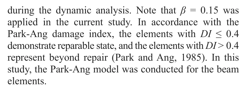
Figure 22 indicates the damage index of the beam elements for DBE and MCE events. As can be seen from Fig. 22, for both the DBE and MCE events, the local damage in the beam elements of the conventional model is significantly higher than that of the MRWF models. For example, under the MCE events, the maximum damage index of the beam element for the conventional model is equal to 0.78, representing the structural damage beyond reparability. Comparing the MRWF models to each other, it can be observed that the M-1r exhibits a maximum damage index of 0.33 for MCE events, whereas the other MRWF models reveal a damage index less than 0.2 for all cases. Interestingly, even under MCE records, the M-3ir has a damage index lower than 0.05. These results are attributed to the reduction of undesirable effects of wall-to-frame interaction at the MRWF models with a greater number of wall panels and smaller wall width.
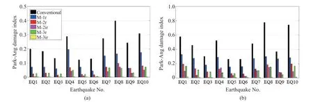
Fig. 22 Maximum damage index in the beam elements according to Park-Ang model (1985): (a) DBE events, (b) MCE events
Fig. 23 Residual drift ratio in the roof under single and multiple earthquakes
One of the main motivations for developing seismic resilient systems is that the structure can tolerate the main- and after-shock seismic sequences that may occur during the life of a building. To this end, the models were subjected to the three seismic sequences reported in Table 3. Using the main-shock earthquakes, the initial damage can be produced to the structures, and by applying the after-shock events, the seismic behavior of the structures with existing damage can be evaluated. In fact, it is impossible for a structure to encounter two earthquakes with the intensity level of MCE. Accordingly, each seismic sequence included a MCE event followed by a DBE earthquake (Songet al. 2015). To consider the rest of the building, an interval of 40 s was incorporated between the first and second earthquakes.
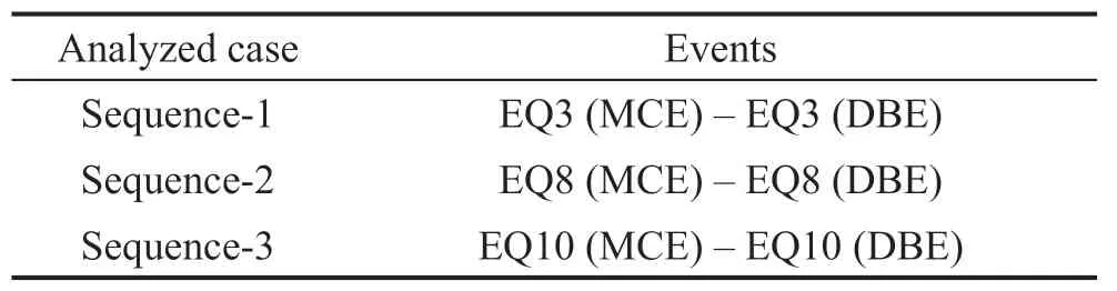
Table 3 Applied seismic sequences
Figure 23 shows the residual drift ratio results under main- and after-shock seismic sequences. As can be seen, the residual drift ratio tends to increase for the conventional model. For instance, under sequence-2, the residual drift ratio of the conventional model is increased up to 0.42%. On the contrary, due to the selfcentering ability, the residual drifts of the MRWF models are negligible under various seismic sequences. From these results, it can be stated that the MRWF models can provide seismic resilient systems which can quickly recover their performance after single and multiple earthquakes.
6 Conclusion
In this study, a precast concrete multiple rocking wall-frame (MRW) system was examined. Five MRWF models together with a conventional model were investigated. In the MRWF models, the numbers and arrangement of wall panels were varied in such a way that the total effective width of the wall panels was kept the same for all models.
The performance of the MRWF models was evaluated through cyclic and time history analyses. The numerical results showed that by decreasing the number of walls and increasing the wall width, local damage occurred in the structural elements of the frame due to undesirable wall-to-frame interaction, which led to imperfect flagshaped hysteretic behavior. However, by increasing the number of walls as well as decreasing the wall width, lower force demands were transmitted from the walls to the frame. As a result, the dampers dissipated the most of energy, such that the primary structural elements remained elastic with little damage. Due to these results, the MRWF system provides better flag-shaped hysteretic behavior which results in negligible roof residual drifts and a damage index of less than 0.2 under extreme earthquakes.
On the contrary, in the conventional model, the formation of plastic hinges at the wall-base and undesirable wall-to-frame interaction led to extensive damage beyond reparability, which not only exacerbates the performance of the system under earthquake records but can also result in demolition of the building after a severe earthquake.
Generally, it can be declared that the proposed system not only has a comparable response to conventional shear wall systems in terms of lateral strength, but also has the benefit of self-centering ability, which leads to negligible residual drifts. Accordingly, a seismic resilient system is attained, enduring severe earthquakes and mainshock-aftershock seismic sequences. These systems are expected to be a valuable addition to the application of precast concrete buildings in practice.
杂志排行

Earthquake Engineering and Engineering Vibration的其它文章
- Dynamic shear modulus and damping ratio characteristics of undisturbed marine soils in the Bohai Sea, China
- Geotechnical engineering blasting: a new modal aliasing cancellation methodology of vibration signal de-noising
- Response prediction using the PC-NARX model for SDOF systems with degradation and parametric uncertainties
- Probability-based analytical model for predicting the post-earthquake residual deformation of SDOF systems
- Seismic behavior of multiple reinforcement, high-strength concrete columns: experimental and theoretical analysis
- Performance-based global reliability assessment of a high-rise frame-core tube structure subjected to multi-dimensional stochastic earthquakes