Seismic performance of a rectangular subway station with earth retaining system
2022-01-21MaChaoLuDechunDuXiuliandQiChengzhi
Ma Chao, Lu Dechun, Du Xiuli and Qi Chengzhi
1. Beijing Advanced Innovation Center for Future Urban Design, Beijing University of Civil Engineering and Architecture, Beijing, China
2. Institute of Geotechnical and Underground Engineering, Beijing University of Technology, Beijing, China
Abstract: Much effort has been made in investigating the seismic response and failure mechanism of rectangular subway stations, however, the influence of earth retaining systems has generally been ignored in previous studies. This paper presents a numerical study on the seismic performance of a rectangular subway station with/without earth retaining systems by taking fender piles as the example, and aims to illustrate how the existence of fender piles affects seismic responses on subway stations. The loading conditions of subway stations and their surrounding soils prior to earthquakes are discussed.Next, seismic responses of subway stations with or without fender piles were simulated. Afterward, earthquake-induced deformations of stations and surrounding soils, as well as the internal forces and damage modes of the structural components,were systematically studied. Consequently, the seismic performance of the stations was affected by the existence of fender piles. In addition, earthquake intensity is illustrated. The study showed that deformation modes of surrounding soils and damage modes of stations were different with regard to the existence of fender piles. Meanwhile, earthquake intensity influencing the seismic performance of stations with or without fender piles were found to be opposite.
Keywords: rectangular subway station; earth retaining system; seismic soil-structure interaction; damage mode; interstory drift ratio
1 Introduction
Damage to underground structures during the Great Hanshin earthquake (Iidaet al., 1996) in Japan, the Koceali earthquake in Turkey (Ghasemiet al., 2000),the Chi-Chi earthquake (Wanget al., 2011) and the Wenchuan earthquake in China (Wanget al.,2009)illustrated that there might be some inadequacies in understanding seismic performance and seismic design of underground structures. Therefore, much effort has gone into revealing the seismic damage mechanism of underground structures (Yamatoet al., 1996; Huoet al., 2005; Maet al.,2019; Lu and Hwang, 2019) and elaborating on the seismic performance (Chenet al.,2015; Yuet al., 2019; Luet al., 2019) of underground structures and tunnels (El Naggaret al., 2008; Debiasiet al., 2013; Yuet al., 2018; Yuanet al., 2018; Zhuanget al., 2019c; Maet al., 2021b). Researchers have generally faced crucial problems, including pore pressure and site liquefication (Zhang and Wang, 2012; Zhouet al., 2014;Zhuanget al., 2018; Wanget al., 2018; Liet al., 2020),seismic wave input (Liet al., 2018; Liuet al., 2019;Sunet al., 2020), artificial boundary conditions (Zhaoet al., 2018; Rezaet al., 2020), relative stiffness between soils and structures (Penzien, 2000; Zhang and Chen,2019), buried depth (Cilingir and Madabhushi, 2010;Chian and Madabhushi, 2012; Zhu and Liang, 2020),the simplified calculation method (Liu and Shi, 2006;Liu and Zhang, 2018; Xuet al., 2019), seismic reduction(Chenet al., 2014; Maet al., 2018a, 2021a), and so on.These studies have resulted in substantial revisions of seismic design codes for underground structures. For example, the Code for Seismic Design of Urban Rail Transit Structures (GB50909, 2014) in China points out that earth retaining systems should be taken into account when using the time-history analysis method to calculate the spatial effect of the seismic performance of underground structures. Standard for Seismic Design of Underground Structures (GB/T 51336-2018, 2018)asserts that the existence of fender walls should be considered during the calculation checking process for open tunnel structures. Howerver, there is no relative statement for other underground structures. Meanwhile,the influence of earth retaining systems was typically ignored in previous studies. It is obvious that earth retaining systems have measurable influences on the seismic responses of underground structures, but that influence requires more quantified evaluations.
Seismic investigations (Gazetaset al., 2004, 2005)have demonstrated, for example, that the retaining system of the Kerameikos station survived with no visible damage during the 1999 Koceali earthquake,although this temporary retaining system was not designed to withstand earthquakes. Therefore, Gazetaset al. (2004, 2005) conducted numerical studies on the seismic responses of a foundation trench with retaining systems. Numerical results show that the earthquakeinduced axial forces of anchors were insignificant, but the bending moments within the fender walls were large.Unfortunately, the seismic performance of the subway station, in particular as influenced by the retaining system, was not considered. The seismic responses of frame subway stations with diaphragm walls were simulated by Wang (2011) and Zhuanget al. (2019b).In Wang′s study, the author mainly focused on the deformations of the surrounding soils and did not discuss the dynamic responses of the station. Whereas, Zhuanget al. (2019b) not only analysed the liquefication of the surrounding soils but also paid special attention to the dynamic responses of the station. Analyses noted that the diaphragm walls improved the seismic performance of the subway station. The existence of retaining systems decreased the uplift of the structure and the maximum horizontal deformation of its upper story. Note that the question of how retaining systems enhance the seismic performance of an underground structure was still not quantifiably exhibited.
Actually, the loading states of an underground structure and its surrounding soils are in a static equilibrium state prior to the onset of an earthquake. This loading state greatly affects the additional loading carrying and deformation capacities of underground structures(Hashashet al., 2001; Gomes, 2013; Maet al., 2018b;Wanget al., 2018; Liet al., 2018; Xieet al., 2018) due to the nonlinear behaviours of concretes, rocks, soils, etc.If the earth retaining systems are not dismantled after the construction of an underground structure, they can help the structure carry part of the soil pressure (Bobetet al., 2008). Then the static loads carried by the structure will decrease. Subsequently, the earthquake-induced deformations and internal forces of the underground structure will be different when considering or ignoring the existence of earth retaining systems.
Therefore, this paper conducts a numerical analysis to investigate the seismic performance of a rectangular underground structure as influenced by earth retaining systems. The target structure is a rectangular subway station that uses fender piles as an earth retaining system during construction. The structural internal forces of the station with or without fender piles prior to earthquakes were illustrated. Next, the seismic responses of the station with or without fender piles were simulated by employing three earthquake records. The differences between the damage modes of the two structures were also illustrated. Moreover, the earthquake-induced deformations and internal forces of the structures were presented. In particular, earthquake intensity influencing the seismic responses of the two structures was analysed contrastively.
2 Numerical analysis setup
2.1 Case introduction
A subway station under construction located in Luoyang, Henan province, China, was selected as the target structure for this study. This station is a typical rectangular-shaped underground structure with a doublestorey-three-span, and was constructed using the cutand-cover method. The fender piles, which are typically used cast-in-place piles, were used as an earth retaining system. Before the excavation of the foundation trench,pile holes with a net distance of 1.0 m were bored.Next, steel reinforcement was placed in the holes, and reinforced fender piles were cast. During the excavation of the foundation trench, the fender piles were used to prevent the soil from sliding into the foundation trench.Meanwhile, concrete was sprayed between the piles.The shotcrete and piles formed fender walls. The fender walls were not dismantled during the construction of the station. On the contrary, manual chiselling was conducted on the surface of the fender walls, and the chiselled fender walls as the formwork had concrete applied to the sidewalls of the station. Therefore, the fender piles and the structure acted as a loading carrying system once the construction of the subway station was completed.
The subway station had the buried depth of 4.10 m;its cross-sectional dimensions are shown in Fig. 1. The outer dimension of this station is 22.70 m in width and 13.90 m in height. The thickness of the sidewalls is 0.70 m.The upper, middle and bottom slabs have thicknesses of 0.70 m, 0.40 m and 0.90 m, respectively. The crosssection of the central columns is 0.70 m × 1.10 m. The net spacing of the columns is 8.00 m. The distributed rebars of all components are listed in Fig. 1(c). The crosssectional dimension and distributed rebars of the fender piles are presented in Fig. 1(d). Natural soil stratum conditions of the surrounding soils are illustrated in Table 1. Moreover, the stratum to a depth greater than 50 m can be treated as rigid bedrock because the velocity of the shear wave is larger than 500 m/s (GB 50909, 2014).
2.2 Numerical model

Fig. 1 Description of the subway station (Unit: mm), (a) 3D model of the subway station, (b) cross-sectional dimensions of the station, (c) distributed rebar design, (d) cross-sectional dimensions of the fender piles

Table 1 Properties of the surrounding soils
Two 3D FEM models were built using the finite element software of ABAQUS/CAE for the nonlinear soil-structure dynamic interaction, whose size is 160 m ×50 m × 19 m. One model is a hypothetical structure that has no fender piles, and is employed as a contrastive case. The other is the model of the target structure.Figure 2 presents the station with fender piles. Eightnode hexahedron reduced integration elements were used to mesh the subway stations, fender piles and soils.Truss elements were embedded in concrete to model the rebars. The finite element meshes of the stations, fender piles and soils are shown in Fig. 2. Because the site and laboratory tests only provide the material parameters of the inner frictional angle (φ) and the cohesion (c) of soils, the Mohr-Coulomb constitutive model was used to simulate the surrounding soils. The corresponding model parameters of each stratum obtained from the laboratory tests are listed in Table 1. During the design phase, concrete with a strength level of No. C50 was used for columns, and concrete with a strength level of No.C30 was used for other parts of the stations and fender piles. The concrete damage plasticity model (Lublineret al., 1989; Wanget al., 2018) was used to describe the behaviours of concrete. The corresponding material parameters are shown in Tables 2 and 3. Moreover, the idealized elastoplastic model was selected for the rebar,whose material parameters are density=7800 kg/m3and yield stress=400 MPa.

Fig. 2 Finite element meshing system for the FEM model, (a) surrounding soils, (b) station and fender piles, (c) rebars
Additional viscous-damping was separately involved and assumed to exhibit Rayleigh damping.

herein,KandMare stiffness and mass matrixes.ζis the damping ratio of the fundamental mode, taken as 5% in this analysis.ω1andω2are the first and second natural vibration frequencies of the system. The calculatedαandβare 0.078 and 0.032, respectively.
The behaviour of the interfaces between the soils and stations, as well as between the soils and fender walls, is simulated via dynamic contact. In the normal direction of the interface, the normal contact compressive stress (σn)mutually transfers via the contact constraint. The contact will open when normal stress is tensile stress, then the contact surface changes into mutual free surfaces.The Coulomb′s friction law was used to simulate the tangential contact shear stress on the interface (Jiangetal., 2010). When shear stress is larger than shear strength(τf), sliding will occur along the interface.τfis defined as:

Table 2 Material parameters of concrete No. C30

Table 3 Material parameters of concrete No. C50

herein,µis the friction coefficient of the interface between the soils and concrete; its value was selected as 0.4, which is referred to previous studies (Huoet al., 2005; Maet al., 2019). For the target station, the fender piles were not dismantled, but manual chiselling was conducted at the surface and the chiselled fender piles as the formwork were concreted with the sidewalls of the station. The fender piles and the sidewalls were tied together without any relative movement during the simulation.
According to a study done by Liet al.(2018), tied degrees of the freedom boundary, in which the degrees of the freedom of the lateral boundary nodes are coupled,was selected to avoid a possible wave reflection issue with truncated boundaries. The ground motions obtained from the Great Hanshin earthquake and the Chi-Chi earthquake, which caused severe damage to underground structures, as well as an artificial earthquake, were used in this paper. Their accelerations in time of history are shown in Fig. 3. The Fourier amplitude spectrum of all of the earthquakes is also shown in Fig. 3, The predominant periods of earthquakes are between 0.2 s-0.8 s. Shaking of the ground occurs in the cross-section of the station.During numerical simulations, the PGAs are adjusted to 0.1 g, 0.2 g, 0.3 g and 0.4 g.

Fig. 3 Ground motions used during simulations, (a) Great Hanshin earthquake, (b) Chi-Chi earthquake, (c) artificial earthquake,(d) Fourier spectra
3 Loading states of stations before earthquakes
The static equilibrium states of the stations with or without fender piles only under gravity are first calculated. The loading states of the stations are rather different when considering the existence of the fender piles. This could be proved by studying the internal forces within structural components, such as the shear force within the sidewalls. The obtained shear forces within the sidewalls of the two stations are shown in Fig. 4.The shear forces presented are the internal forces within the sidewalls with a length of 1.0 m. The monitoring section of the sidewalls is presented in Fig. 2(b). As presented, the shear forces within the sidewalls of the station are generally larger when ignoring the influence of the fender piles. The maximum value of the shear forces within the sidewalls of both stations are at Section D-D′; the maximum shear forces within the station without fender piles are about 1.30 times that of the station with fender piles. Namely, the existence of the fender piles reduces 30% horizontal soil pressure acting on the sidewalls. This is because part of the horizontal soil pressure is carried by the fender piles.
On the other hand, because all of the vertical loading carrying components of the rectangular underground structure consist of the sidewalls and central columns(Maet al., 2019), monitoring of the axial forces within the sidewalls and central columns in four sections shown in Fig. 1(d) and present in Table 4. The axial forces within the sidewalls are also the average axial forces undertaken by the sidewalls with a length of 1.0 m. As mentioned above, the fender piles are used to prevent the surrounding soils from sliding to the top of the structure; the gravity of the overlying soils carried by the structure is reduced when fender piles exist. Therefore,the axial forces (N1) within the sidewalls and columns of the station without fender piles, including the upper and bottom storeys, are larger thanN2, which is obtained from the station with fender piles. The ratio, as seen in Table 4, which is calculated byN1/N2, demonstrates that the existence of the fender piles reduces by at least 10%vertical loads that are acting on the station.
To compare the vertical loads respectively carried by the sidewalls and central columns, the axial forces within the sidewalls with a length of 9.0 m should be calculated. This is because the net distance between columns is 8.0 m and the width of the columns is 1.0 m.The calculations are shown in Eq. (4).

It can be concluded that all the vertical loads carried by the columns are approximate to those carried by each sidewall on the same story, which confirms that columns are the key vertical supporting component.
Figure 5 presents the generalized plastic shear strain,εp, nephograms of the soils. Herein,εpis expressed as:

Fig. 4 Shear forces within the sidewalls

4 Seismic performance of stations and surrounding soils
The seismic responses of both stations under three ground motions with four PGAs were simulated. The inter-storey drift ratio and axial load, which are widely used to analyse the seismic performance of rectangular underground structures (GB 50909, 2014; Chenet al.,2016; Luet al., 2019; Zhuanget al., 2019a), were selected as the indicators to estimate the seismic performance of the stations. The seismic responses, especially maximum deformations and forces, of the two stations influenced by the earthquake intensity, will also be discussed in this section.
4.1 Seismic performance of surrounding soils
Ground deformation can be used to describe the intensity of the dynamic interaction between the stations and surrounding soils. The relatively larger strain around the structures indicates a stronger interaction between soils and structures. Figure 6 illustrates that the distribution modes ofεpafter the Great Hanshin earthquake with a PGA of 0.2 g agrees well with the modes that exist only under gravity loads. After the earthquake, theεpof the surrounding soils shows a larger increase when ignoring the fender piles. Meanwhile, the plastic deformation area of soils the station is expanded greatly. However, there is almost no plastic deformationin the surrounding soils surrounding the station lack fender piles. Note that, after earthquakes the plastic deformation around the bottom of the fender piles increases; this is because a dynamic interaction also exists between soils and fender piles. The horizontal stiffness of fender piles is larger than that of the soils at the same position; therefore, the deformation of the soils is larger than that of the piles during earthquakes (Huoet al., 2006). In particular, the relative movement between the end of fender piles and soils is more serious, which results in a larger deformation of soil at the bottom of fender piles. The increase of the value and area ofεpof the surrounding soils illustrates that the interaction between the station and surrounding soils is more intensive when ignoring the existence of fender piles.

Table 4 Axial forces within the columns and sidewalls
4.2 Damage mode of the stations
The existence of the fender piles also affects the damage mode of the stations. Figures 7 and 8 present the damage nephograms of the stations after ground motions with different PGAs. As presented in Fig. 7(a), the damage to the station generally starts from the base of the sidewalls when ignoring the existence of the fender piles. Moreover, the damage to the bottom columns is more serious than that observed in the upper columns.

Fig. 5 εp nephograms of the surrounding soils prior to earthquakes (unit: %), (a) station without fender piles, (b) station with fender piles

Fig. 6 εp nephograms of the surrounding soils after the Great Hanshin earthquake with a PGA=0.2 g (Unit: %), (a) Station without fender piles, (b) Station with fender piles

Fig. 7 Damage nephograms of the station after the Great Hanshin earthquake with different PGAs when ignoring the fender piles,(a) PGA=0.3 g, (b) PGA=0.4 g
Note that joints between the middle slab and beams are also damaged, shown in Fig. 7(b). This is because the rigidity of the beams is much larger than that of the middle slab. Rotation will occur around the ends of the middle slab during earthquakes. Moreover, this also proves that there is damage at the restrained ends of the eversion beams, which indicates that the earthquake-induced horizontal soil pressure is also harmful to eversion beams. In brief, the columns and bases of the sidewalls,as well as the ends of the thin middle slab, experience more damage than other parts during earthquakes when the fender piles are not taken into account.
The damage mode of the station changes significantly when considering the existence of the fender piles, as presented in Fig. 8. First, the damage of the station is slighter under the same intensity of earthquakes. For example, when PGA=0.4 g damage to the sidewalls and central columns is smaller than 0.2, damage at the same positions of the station without fender piles reaches 0.8. Secondly, damage to the station starts from the joints between the bottom slab and sidewalls as shown in Fig. 8(a). There is also damage at the joints between the middle slab and beams. This finding is similar to the study done by Zhuanget al.(2019b). Therefore, the ends of the middle slab are in the weak position and should be paid special attention during the seismic design of rectangular underground structures. Moreover, when under the influence of earthquakes with a PGA of 0.4 g, the fender piles also experience slight damage. The damage is mainly observed at the positions that connect with the top and bottom slabs. This is because the cantilevered parts of the fender piles are in a bending state when under earthquake-induced soil pressure. Larger bending moments cause damage to the fender piles at these positions.
4.3 Deformations and internal forces of the stations
4.3.1 Horizontal deformation
Figures 9(a) and 10(a) show horizontal deformation of the sidewalls and central columns of the two stations with regard to time-history in the case of the Great Hanshin earthquake, which had a PGA of 0.2 g. The horizontal deformation is the relative horizontal displacement between both ends of the sidewalls and central columns.The drift ratios, shown in Figs. 9(b) and 10(b), are calculated by dividingthe horizontal deformations of structural components by their heights. As presented, the horizontal deformations of the components at the bottom storey are larger than those of the top storey. In particular,the residual deformations of the bottom sidewalls and columns of the structures are about 2.0 mm when ignoring the existence of the fender files, which are 2.5 times larger than those when considering the existence of the fender piles. Meanwhile, the drift ratios of the columns,especially the bottom columns, are larger than those of the sidewalls. This illustrates that the columns should be given more attention during the seismic design of rectangular underground structures.

Fig. 8 Damage nephograms of the station after the Great Hanshin earthquake with different PGAs when considering the fender piles, (a) PGA=0.3 g, (b) PGA=0.4 g
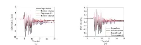
Fig. 9 Deformations of the station under the Great Hanshin earthquake without PGA=0.2 g when ignoring the fender piles,(a) horizontal deformation, (b) drift ratio

Fig. 10 Deformations of the station under the Great Hanshin earthquake with PGA=0.2 g when considering the fender piles,(a) horizontal deformation, (b) drift ratio
The dynamic responses of the two stations during each ground motion were also simulated. The obtained maximum drift ratios of the sidewalls and columns are provided in Table 5. The relation between the PGA and drift ratios of the stations are plotted in Figs. 11 and 12,respectively. As presented, the larger the PGA, the larger will be the maximum horizontal deformations of both stations. And the drift ratios of each component of the two stations becomes nonlinearly larger with an increase of the PGA, especially when ignoring the existence of the fender piles. Define the maximum deformation ratio of structural components,RD, as Eq. (6).


Fig. 11 Relation of the PGA and drift ratio of the station when ignoring the fender piles, (a) Great Hanshin earthquake, (b) Chi-Chi earthquake, (c) artificial earthquake

Table 5 Maximum seismic responses of two stations during various earthquakes

Fig. 12 Relation of the PGA and drift ratio of the station when considering the fender piles, (a) Great Hanshin earthquake,(b) Chi-Chi earthquake, (c) artificial earthquake
where,Δ1is the maximum horizontal deformation of components in the station with fender piles, andΔ0is the maximum horizontal deformation of components in the station without fender piles.RDis used to quantify the difference between the deformation responses of the stations with or without fender piles. Plot the curves of PGA versusRDin Fig. 13. In this figure, the capital letters G, C and A represent the Great Hanshin earthquake,the Chi-Chi earthquake and the artificial earthquake.The values ofRDare generally between 30% and 90%.This indicates the fender piles reduce 10%-70% of the earthquake-induced horizontal deformation of the station.
However, the earthquake intensity influencing the horizontal deformations of the two stations is different.Taking the drift ratio of the bottom columns, as shown in Figs. 11(a) and 12(a) as an example, when taking into consideration of the Great Hanshin earthquake, which had a PGA of 0.1 g, the maximum drift ratios of the stations without and with fender piles are 0.074% and 0.054%. Whereas, the drift ratios respectively increase to 0.776% and 0.429% when the PGA=0.4 g, which show 10.5 and 7.9 times increases. This indicates that the earthquake intensity influencing the horizontal deformation response of the station without fender piles is more remarkable.

Fig. 13 PGA versus RD of the stations
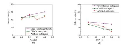
Fig. 14 Relation of the PGA and θ, (a) ignoring the fender piles, (b) considering the fender piles
Define the average drift ratio of the sidewalls and columns at the same storey as the inter-storey drift ratio.The difference value,θ, between the inter-storey drift ratios of the top and bottom storeys is as Eq. (7).

where,θBandθTare the inter-storey drift ratios of the bottom and top storeys. The different ratios of all the cases are calculated and illustrated in Figs. 11 and 12 and include all relevant numbers. Meanwhile, the relations between PGA andθare plotted in Fig 14, which presents thatθof the station without fender piles becomes larger with the increase of PGA. The minimum value is larger than 40%. However,θhas a decreasing trend when taking into account the fender piles: the maximum value is less than 40%. Therefore, it is considered conservative when designing a rectangular underground structure without considering the existence of fender piles. In other words, the existence of the fender piles could not be ignored during the seismic design of rectangular underground structures, especially under the influence of strong earthquakes.
4.3.2 Shear forces within the sidewalls
Figure 15 shows the shear force responses of the stations during the Great Hanshin earthquake, with a PGA of 0.2 g. The shear forces are monitored at Section D-D′ as shown in Fig. 1(d). D-D′ is the section in which the shear forces have the largest value when only under the influence of gravity. The shear forces are also the internal force within the sidewalls, with a length of 1.0 m. As shown, the maximum shear force within the sidewalls of the station without fender piles is 462 kN/m.Whereas, the maximum shear force within the sidewalls decreases to 363 kN/m when taking into account the fender piles, which register a 21.4% decrease. Therefore,the earthquake-induced horizontal loads imposed on the station are reduced when considering the existence of the fender piles.
On the other hand, static soil pressure forces the sidewall towards the structure before earthquakes occur.However, the horizontal seismic loads cause structure rocking during earthquakes. In that case, the direction of the shear forces within the sidewalls of the structure will change during the occurrence of earthquakes. As Fig. 15 presents, for the station without fender piles the direction of the shear forces within the sidewalls varies between 4.5 s and 7.5 s of the earthquake. When earthquake loads force the station to move to the right, the shear force in the right sidewall decreases. Subsequently, it decreases to zero, then increases, but the direction is opposite.When earthquake loads force the station to the left, the direction of the shear force in the left sidewall has a similarly opposite effect. Additionally, when considering the existence of the fender piles, the direction of shear forces within the sidewalls does not change. This is because the horizontal rigidity of the structure is enhanced and the rocking effect does not occur.
The obtained maximum shear forces at Section D-D′during earthquakes are listed in Table 5. The curves of the PGA versus the maximum shear force are plotted in Fig. 16. As presented, the larger the PGA, the larger will be the maximum shear forces within the sidewalls of both stations. Define the maximum shear force ratio,RF, as Eq. (8).

where,S1is the maximum shear force within the sidewalls of the station with fender piles, andS0is the maximum shear force within the sidewalls of the station without fender piles.RFis used to quantify the difference between the force responses of the stations with or without fender piles. Plot the curves of PGA versusRFas shown in Fig. 17.
When the PGA is smaller than 0.2 g, the obtained maximum shear forces within the sidewalls of the station with fender piles is much smaller. The values ofRFare between 70% and 90% when the PGA is smaller than 0.2 g, as shown in Fig. 17. This indicates that the fender piles reduce 10%-30% of earthquake-induced horizontal loads acting on the station. But when the PGA is greater than 0.3 g, theRFmight be larger than 100%, such as the Chi-Chi earthquake, with PGAs of 0.3 g and 0.4 g, and with the artificial earthquake, with a PGA of 0.4 g. The largest value is greater than 120%.This does not mean that the earthquake-induced loads acting on the station are much greater. As shown in Figs. 7 and 8, when under the effects of earthquakes with a PGA of 0.4 g, the damage to the sidewalls in the station without fender piles is much more serious, as their lateral rigidity and shear loading carrying capacity are reduced greatly. Thus, the horizontal loads carried by the sidewall decrease. By comparison, when the damage to the sidewalls in the station with fender piles is lesser,then the decrease of the shear loading carrying capacity of the sidewalls is slight. Consequently, the maximum shear force within the sidewalls is much larger.
5 Discussion

Fig. 15 Shear force response within the sidewalls under the Great Hanshin earthquake with a PGA=0.2 g

Fig. 16 PGA versus maximum shear force within the stations

Fig. 17 PGA versus RF of the stations
The existence of the fender piles is beneficial for the stability and seismic resistance of the underground structure. For the target structure, prior to earthquakes,the fender piles can reduce 30% soil pressure on the sidewalls and at least 10% vertical loads caused by the gravity of the overlying soils. The existence of the fender piles also results in differences in the seismic performance between two structures, including the damage mode of the structures, the deformation mode of surrounding soils, earthquake-induced deformations and internal forces of the structural components.
The horizontal rigidity of the station is enhanced when the fender piles exist, and the relative rigidity ratio between the structure and soil is also increased.Subsequently, the intensity of the dynamic interaction between the station and surrounding soils is decreased.As a result, the deformation of the surrounding soils surrounding the station is smaller. The earthquakeinduced horizontal loads acting on the structure are also reduced because the fender piles can carry a portion of the seismic loads. Therefore, the earthquake loads could not force structure rocking in surrounding soils.Moreover, the earthquake-induced deformations and internal forces of the station are smaller (Huoet al., 2006)and the damage to the entire station is lighter during the same earthquake. For the target structure, the fender piles reduced at least 10% deformations and internal forces of the station induced by earthquakes. Therefore,the seismic design of an underground structure is much more conservative when ignoring the existence of fender piles. On the other hand, earthquake-induced horizontal soil pressure forces the cantilevered parts of fender piles in a bending state. The fender piles that connect with the top and bottom slabs will be damaged during strong earthquakes.
Although numerical results show that the seismic response of the columns on the bottom story is more serious, the seismic performance rules of rectangular underground structures are different when ignoring or considering the existence of the fender piles.When considering the existence of the fender piles,θdemonstrates a decreasing trend with an increase in earthquake intensity. On the other hand, the difference between the damage modes of the two structures,especially the first damage components, illustrates that the seismic failure mechanism of rectangular underground structures is different when considering the existence of fender piles. Therefore, deep analyses are necessary, using the conclusions drawn from a study of the structures that lack earth retaining systems for the purpose of creating seismic designs for rectangular underground structures.
6 Concluding remarks
The fender piles are the typically used earth retaining systems during the construction of underground structures and will not be dismantled after construction.Therefore, the fender piles will influence the loading carrying capacity and seismic performance of underground structures, a topic that has not previously been studied in a systematic fashion. In this study, the numerical simulation method is used to analyse the seismic responses of rectangular underground structures with or without fender piles by taking a subway station as an example. The fender piles influencing the loading states of subway stations prior to the occurrence of earthquakes were first discussed. Then the seismic responses of the subway stations and surrounding soils under three ground motions with four PGAs were simulated. The deformation of the surrounding soils, as well as the damage mode and drift ratio of the structures and the shear forces within the sidewalls were systematically discussed. Consequently, suggestions for the seismic design of underground frame structures were presented. The main achievements of this study could be summarized as follows.
(1) For the target structure, the existence of the fender piles reduces horizontal soil pressure and vertical loads acting on the structure. Therefore, the influence of the fender piles must be considered when simulating the seismic responses of underground structures.
(2) The existence of the fender piles changes the deformation mode of the surrounding soils and damage mode of the structures. The damage to the structure without fender piles starts from the bases of the sidewalls, whereas, damage to the structure with fender piles centers on the ends of the bottom slab.
(3) The seismic responses for both structures become more intensive with an increase of the PGA of earthquakes. The seismic response of the structure without fender piles is rather intensive than that of the structure with fender piles. When considering the influence of the fender piles, the difference between the deformations of the components on the top and bottom stories shows a decreasing trend with an increase in PGA. Meanwhile, the rocking effect of the structure does not occur when fender piles exist.
(4) This study mainly presents a discussion of the seismic response rules of rectangular subway stations without or with fender piles. Hence, in the future, the seismic failure mode and the corresponding mechanism of underground structures when considering fender piles should be studied further as independent topics.
Acknowledgement
This study was supported by the National Natural Science Foundation of Beijing (8212007), the National Natural Science Foundation of China (51808028,52025084, 51778026), the Pyramid Talent Training Project of Beijing University of Civil Engineering and Architecture (JDYC20200311) and the Fundamental Research Funds for Beijing University of Civil Engineering and Architecture (X18147).
杂志排行
Earthquake Engineering and Engineering Vibration的其它文章
- Serviceability evaluation of water supply networks under seismic loads utilizing their operational physical mechanism
- Improving the seismic performance of base-isolated liquid storage tanks with supplemental linear viscous dampers
- Seismic fragility analysis of bridges by relevance vector machine based demand prediction model
- Over-height truck collisions with railway bridges: attenuation of damage using crash beams
- Optimization for friction damped post-tensioned steel frame based on simplified FE model and GA
- Development of a double-layer shaking table for large-displacement high-frequency excitation