Analytical evaluation and experimental validation on dynamic rocking behavior for shallow foundation considering structural response
2022-01-21KilWanKoJeongGonHaandDongSooKim
Kil-Wan Ko, Jeong-Gon Ha and Dong-Soo Kim
1. Department of Civil and Environmental Engineering, UC Berkeley, California 94720, USA
2. Advanced Structures and Seismic Safety Research Division, Daejeon 34057, Korea
3. Department of Civil and Environmental Engineering, KAIST, Daejeon 34141, Korea
Abstract: The challenge in the practical application of rocking foundations is the estimation of its performance, particularly the rotation angle, during a strong earthquake. In this study, the dynamic rocking behavior for a shallow foundation considering structural response was evaluated through two analytical approaches: the conventional soil-foundation-structure interaction(SFSI) governing equation of a single-degree-of-freedom (SDOF) structure on a rocking shallow foundation, and the Housner rocking model (i.e., a rocking rigid block on a rigid base). Both approaches were validated with dynamic centrifuge tests.The test models consisted of a soft soil deposit, a shallow rectangular foundation, and an SDOF structure dominated by a bending behavior. A total of 11 foundation-structure systems and six seismic waves, including recorded earthquake signals and sinusoidal waves, were utilized. The results showed that the conventional SFSI equation well predicted the maximum rotation during strong earthquakes. However, this method was less accurate regarding the rotational phase information and maximum rotation of the foundation during weak earthquakes. On the other hand, although the modified Housner′s rocking model required five parameters relevant to a soil-foundation-structure system, it overestimated the maximum rotation of the foundation when compared with the results from dynamic centrifuge tests.
Keywords: soil-foundation-structure interaction; maximum rotation angle; rocking foundation; Housner rocking model;dynamic centrifuge test
1 Introduction
The necessity for a new paradigm of seismic design has been highlighted over the past three decades to handle extremely strong earthquakes (Priestley, 1993). As the available information about earthquakes has increased and the techniques for seismic analysis have advanced,force-based design has been replaced by performancebased seismic design, which is based on the performance of a structure and considers nonlinear behavior(Priestley, 2000; Priestlyet al., 2007). However, during an unexpected strong earthquake, a nonlinear and plastic response is exhibited by not only a structure but also a soil-foundation system (Anastasopouloset al., 2010).Fortunately, the approach of allowing plastic behavior of the soil-foundation system has been investigated as a replacement for prohibiting inelastic behavior of the soil-foundation system (Mergos and Kawashima, 2005;Pecker, 2006).
In particular, the rocking response among the plastic behaviors of soil-foundation systems during an earthquake have attracted research attention after Housner (1963). Various studies characterize rocking behavior through analytical, numerical, and experimental approaches (Yimet al., 1980; Apostolouet al., 2007; DeJong, 2012; Di Egidioet al., 2014; Vetret al., 2016; Ther and Kollár, 2017). Although Housner(1963) studied the rocking response of a rigid block on a rigid base, the flexibility of a superstructure and the deformability of a support base can affect the rocking response of soil-foundation-structure systems (Pelekiset al., 2018). In the aspect of structural rocking, a superstructure was designed as a rigid or linear elastic superstructure. Makris and Konstantinidis (2003)introduced the rocking spectrum of a rigid block on a rigid base and compared it with the seismic response of a single-degree-of-freedom (SDOF) structure. Kavvadiaset al. (2017) attempted to obtain a correlation between the rocking response of a rigid block and ground motion intensity measures. To evaluate the maximum rotation of a foundation-structure system, Zhanget al. (2019)proposed an equation to estimate the maximum rotation angle for a flexible superstructure on a rigid base using a simple analytical model for the representation of nearfault strong ground motions proposed by Mavroeidis and Papageorgiou (2003). However, most studies on structural rocking considered a rigid base and did not examine soil as a base.
In the geotechnical aspect, foundation rocking behavior referred to as “rocking foundation” or “rocking isolation” has been studied intensively over the past two decades (Gajanet al., 2005; Mergos and Kawashima,2005; Gajan and Kutter, 2008; Deng and Kutter, 2012;Gazetas, 2015; Koet al., 2018a, 2018b; Xiaet al.,2020). It was noted that the ultimate moment capacity of the foundation can limit the structural seismic load (Anastasopouloset al., 2013; Kimet al., 2015;Tsatsis and Anastasopoulos, 2015; Koet al., 2021).The challenge in the practical application of a rocking foundation is estimating and minimizing the permanent deformation of the foundation in soil. To reduce the permanent deformation of the rocking foundation,Anastasopouloset al. (2012) and Kokkaliet al. (2015)improved the soil within a shallow depth, where plastic strain largely occurred. Allmond and Kutter (2014),Haet al. (2019), and Koet al. (2019) showed that the unattached pile below the rocking foundation effectively reduced the permanent deformation of the foundation as structural seismic load decreased. Most studies evaluated a rocking foundation using a rigid superstructure.Therefore, to enhance the practical application of the rocking foundation, the foundation must be evaluated using a system with a flexible superstructure on soil,which is close to practical conditions.
Several studies attempted to apply the rocking behavior of a shallow foundation to performance-based design; this was referred to as direct displacementbased design (Paolucciet al., 2008; Denget al.,2014; Hakhamaneshiet al., 2016; Kutteret al., 2016;Khanmohammadi and Mohsenzadeh, 2018). It is crucial to determine the performance of the rocking foundation for the design method. Hence, the maximum rotation of the rocking foundation during strong earthquakes must be investigated. Anastasopoulos and Kontoroupi (2014)and Denget al. (2012) obtained the correlations between the foundation rotation angle and settlement. Kourkouliset al. (2012) conducted the dimensional analysis of the rocking foundation to provide an empirical equation of the toppling rotation of the system as a function of the slenderness ratio (i.e., ratio of the height of the structure to foundation length) and the vertical factor of safety.However, the actual maximum rotation caused by an earthquake is considerably less than the toppling rotation.Gajan and Kayser (2019) reported that the maximum rotation of the foundation was mainly determined by the intensity of shaking. Zhanget al. (2019) utilized dimensionless regression analysis to derive an equation to predict the maximum rotation of the foundation combined with a flexible structure. However, the equation is appropriate for near-fault earthquakes and a system on a rigid base.
The dynamic responses of a structure and foundation system during an earthquake were expressed as a 3 × 3 matrix analytical equation (i.e., three degrees of freedom: net structural response, foundation swaying, and rocking)considering soil-foundation-structure interaction (SFSI)(Kimet al., 2015; Koet al., 2018a). The rocking response of the foundation was derived for a given earthquake signal by utilizing the analytical equation and the structural and physical properties of the foundation(i.e., stiffness and damping). However, it is difficult to precisely determine stiffness and damping because they are affected by nonlinearity and vary during strong earthquakes. Consequently, a simplified method is required to evaluate the maximum rotation of the rocking foundation considering a flexible superstructure on soil for the practical application of the foundation during a strong earthquake.
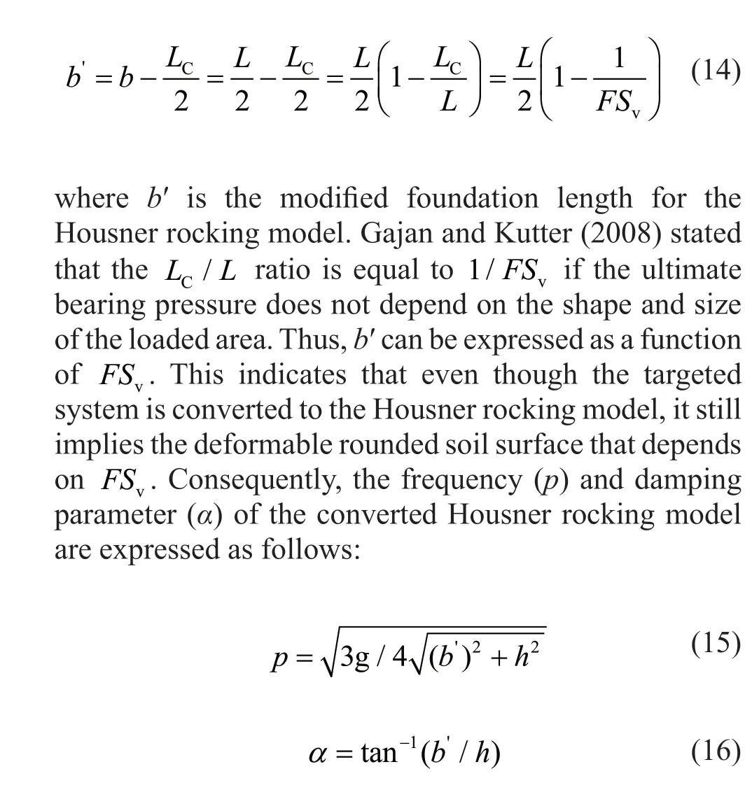
The objective of the present study is to introduce the two analytical approaches to evaluate the maximum rotation of a system with an SDOF structure on a rocking foundation during a strong earthquake using the conventional SFSI equation and Housner rocking model.The governing equation of the Housner rocking model(a rigid block on a rigid base) expresses the rotational response under horizontal ground acceleration (Zhang and Makris, 2001). Thus, first, the Housner rocking model is introduced briefly. The difference between the Housner rocking model and a rocking-dominated two degree-of-freedom (2DOF) system considering the net structural response and rocking motion of the foundation is discussed. Next, a method of evaluating the maximum rotation of the system with the SDOF superstructure on soil using the Housner rocking model is suggested. The maximum rotation from the conventional SFSI equation and the suggested method is compared and validated using the centrifuge test results of rocking foundation models. The analytical models will provide approximate solutions without using finite element methods which need significant computational cost, and provide insight into the physical mechanisms underlying the dynamic rocking foundations.
2 Housner rocking model and rocking foundation with the SDOF structure
2.1 Housner rocking model
Housner (1963) evaluated the rocking response by designing a system consisting of a rigid block on a rigid base (Fig. 1(a)). The width and height of the block are 2band 2h, respectively. The center of gravity of the block is located a distance ofhabove the base and a distance ofbfrom the side of the block. The initial state of the block is rotated as a rotation angle ofθ, and the block exhibits free vibration with two pivots at the end of the side of the block. The rocking behavior of the rigid block changes the pivots fromOtoO′ when the block hits the rigid base. The kinetic energy of the rocking motion is dissipated during impact. The reduction in energy caused by the impact,e, can be derived through the difference in the moment of momentum as follows:

Although Eq. (3) is complex, it can be solved by defining a vector-valued function, which replaces the equation by a first-order ordinary differential equation.This equation can be easily solved using the dimensions of the rigid block and horizontal ground acceleration.Hence, it is a powerful method of predicting the rocking response of the system under earthquake loading.However, the equation assumes a rigid block on a rigid base. It is required to consider soil and an SDOF structure, which allows for structural bending, to apply the equation to practical conditions.
2.2 Rocking foundation with SDOF structure
A structure considering SFSI is generally expressed as a three-degree-of-freedom system: net structural motion (unet), foundation swaying motion (urf), and foundation rocking motion (uθ). The fundamental constitutive equation for the behavior of a structure on a shallow foundation can be derived using Lagrange′s equation (Craig and Kurdila, 2006). It can be expressed as Eq. (4) with a total of three degrees of freedom from the behavior due to the foundation swaying and rocking and the structural bending (Koet al., 2018a), as follows:
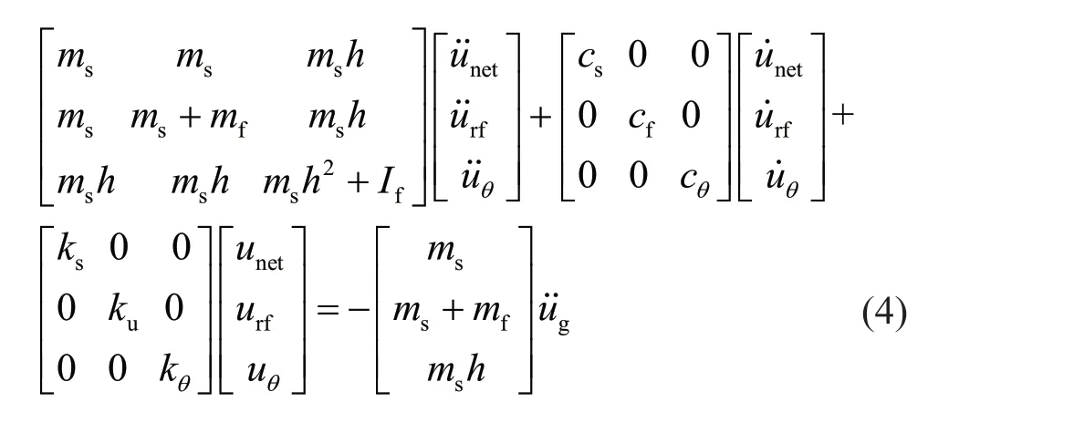

Fig. 1 (a) Housner rocking model: rigid block on a rigid base and (b) rocking foundation with the SDOF structure on soil
wheremsis the effective mass of the structure,mfis the mass of the foundation,Ifis the rotational moment of inertia of the foundation,his the structural height,csis the structural damping coefficient,cfandcθare the damping coefficient of the swaying and rocking of the foundation, respectively,ksis the effective stiffness of the structure, andkuandkθare the swaying and rocking stiffness of the foundation, respectively.
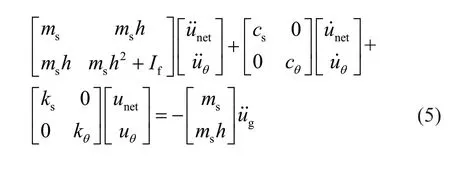
A foundation-structure system with a slenderness ratio larger than one tends to rotate more than slide(Gajan and Kutter, 2009b), and this study aims to develop a simplified method to predict the maximum rotation of the rocking foundation. Hence, the dynamic behavior of the foundation-structure system corresponding to a rocking-dominated system can be described as a 2DOF system comprising net structural motion and foundation rocking motion, without foundation swaying motion(Fig. 1(b)). The conventional SFSI governing equation of the rocking foundation system without swaying can be modified as follows:
The detailed equations utilized to calculate stiffness are summarized by Koet al. (2021). If the structural and physical properties of the foundation (e.g., mass, height,stiffness, and damping) are given, the rocking response of the foundation (uθ) for a givenu˙g˙ can be calculated by using Eq. (5) with the state space representation (Kimet al., 2020). The rocking response of the foundation calculated from Eq. (5) is compared with the rocking response predicted by the method using the Housner rocking model through centrifuge test models. This is described in subsequent sections.
The first row of Eq. (5) describes the horizontal structural motion. The structural seismic load,Fs, during an earthquake is obtained by arranging the first row of Eq. (5) as the following.

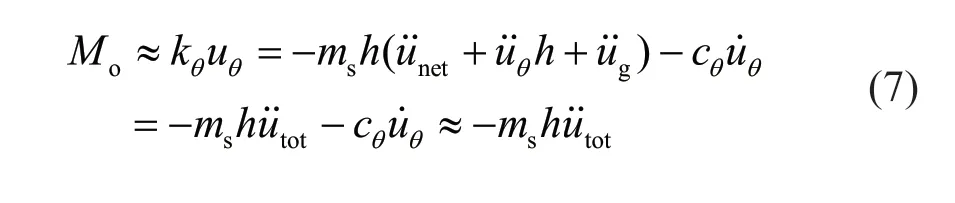
Even if the moment relevant to the rotational damping of the foundation (c uθ θ˙) influencesMo(Kimet al., 2015),u˙˙totis the most crucial parameter that determinesMo(Gajan and Kutter, 2008).Mois approximately expressed by combining Eqs. (6) and (7),as follows:

As shown in Fig. 1(b),Moinduced by structural seismic load is limited by the ultimate moment capacity(Mult) of the foundation, andMultfor the rectangular shallow foundation is calculated as follows (Gajanet al., 2005; Deng and Kutter, 2012; Allmond and Kutter,2014; Koet al., 2018b):

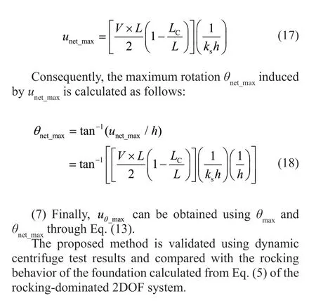
As shown by Eq. (11), the net structural displacement would converge to certain values during a strong earthquake. This relation is used to herein evaluate the maximum rotation of the rocking foundation using the Housner rocking model.
2.3 Comparison between Housner rocking model and rocking foundation with SDOF structure
Representative dynamic rotational behavior of a single lumped mass is discussed. The simplest form of rotational behavior is a simple gravity pendulum (Fig.2(a)). The pendulum rotates freely because it is a lumped mass suspended from a pivot connected by a massless rod. The period of swing of the simple gravity pendulum is expressed as a function of the initial rotation angle and the length of the rod. However, the period is mainly governed by the length of the rod. Similarly, the rocking rigid block is expressed as a lumped mass at the center of the block, and it is referred to as an inverted pendulum(Fig. 2(b)). Its period is proportional to the distance,R.The main difference between the inverted pendulum and simple gravity pendulum is the number of pivots. The inverted pendulum loses kinematic energy when the pivot is changed to the other side of the base because of impact.
As shown in Fig. 2(c), the SDOF structure on the rocking foundation is considered as a single lumped mass at the top of the structure. This mass exhibits not only rotational behavior but also horizontal behavior(structural net motion). Even though the mass of the rocking foundation influences the rocking behavior of the entire system, which is affected by structural inertial motion (inertial interaction), the single lumped mass at the top of the structure is crucial for determining the rocking behavior of the system without the foundation mass. This implies that the dynamic behaviors of the rocking rigid block and the SDOF structure on the rocking foundation are equivalent to that of the single lumped mass with the massless rod. In this aspect,the dynamic behaviors of these two systems can be examined by investigating the dynamic behavior of the single lumped mass in detail. Note that the maximum rotation (θmax) of the rocking rigid block, which is the maximum movement of the single lumped mass during an earthquake, is approximately equal to the maximum rotation of the lumped mass for the SDOF structure on the rocking foundation. This is caused by the rotation of the entire system and the net structural motion

3 Prediction method for maximum rotation angle of rocking foundation with SDOF structure using housner rocking model
Figure 4 shows the steps of the prediction method for the maximum rotation angle of the rocking foundation with an SDOF structure during a strong earthquake. A target structure and a foundation system are converted into the SDOF structure on the rocking foundation. The converted system is assumed to be a 2DOF system: net structural response and foundation rocking. As shown in Fig. 5, the essential information of the converted target structure-foundation system for the prediction method comprises structural stiffness (ks), structural height (h),foundation length (2b=L), the total vertical load of the system (V), and the vertical factor of safety of the system(FSv). The process for the prediction of the maximum rotation angle of the targeted system is described as follows:
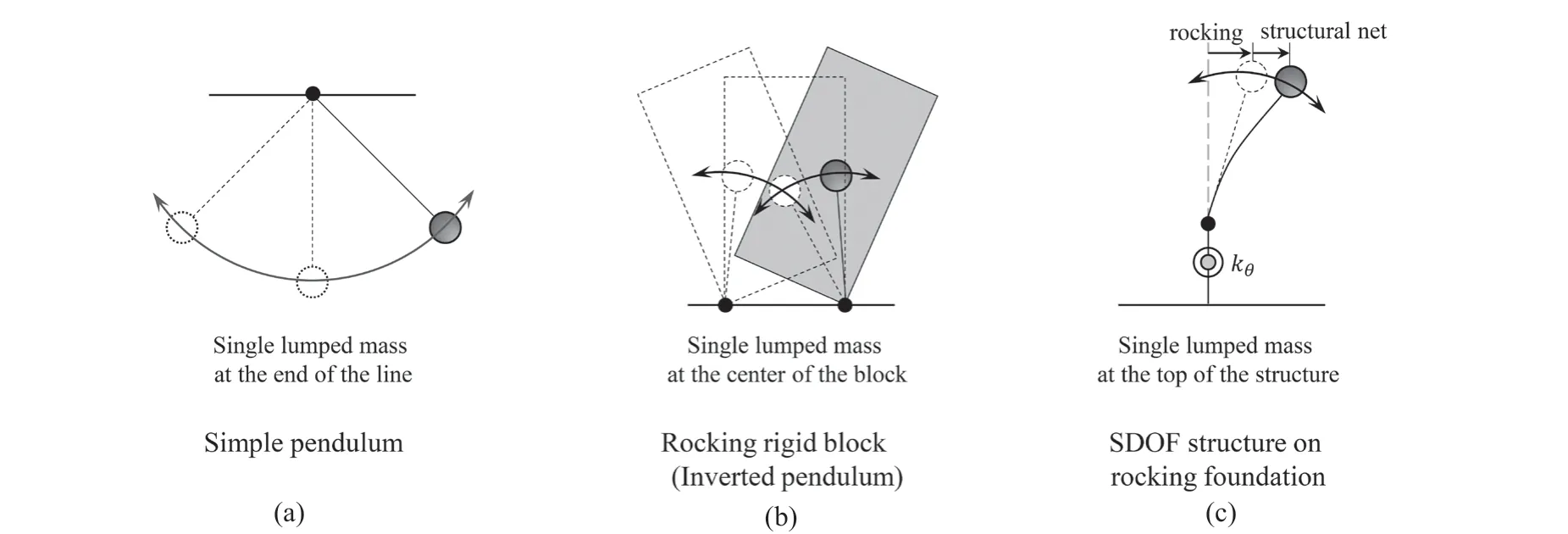
Fig. 2 Dynamic rotational behavior of single lumped mass: (a) simple pendulum, (b) rocking rigid block (inverted pendulum), and(c) SDOF structure on rocking foundation
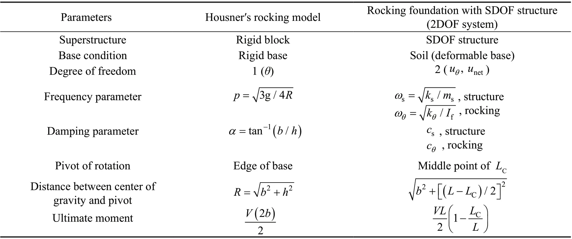
Table 1 Comparison between Housner rocking model and rocking foundation with SDOF structure
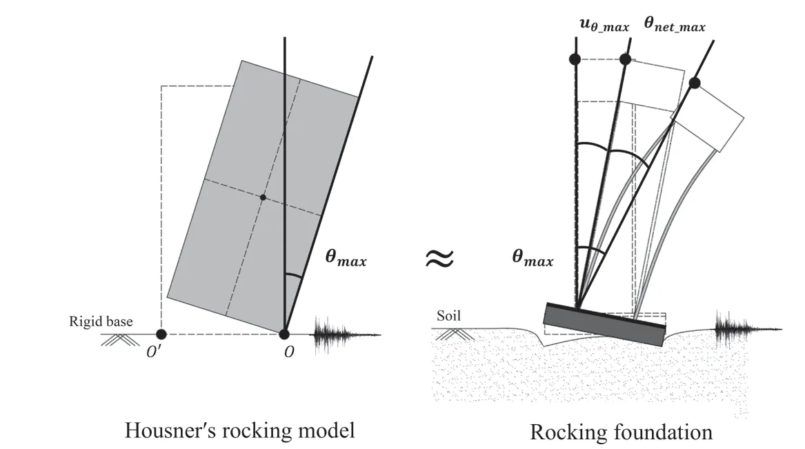
Fig. 3 Relation between maximum rotation obtained using Housner rocking model and rocking foundation with SDOF structure during strong earthquake

Fig. 4 Steps of prediction method for maximum rotation angle of rocking foundation with SDOF structure during a strong earthquake
(1) The bedrock motion is obtained.
(2) Based on the bedrock motion and dynamic soil properties, the free-field motion (u˙g˙) is determined through site response analysis. The calculated freefield motion must have sufficient ability to make the overturning moment (Mo) of the foundation converge to the ultimate moment capacity (Mult) of the foundation during an earthquake.
(3) As shown in Fig. 6, the dimensions of the rocking foundation with the SDOF structure are converted to the Housner rocking model by focusing on the center of mass. WhenMoconverges toMult, the two pivots of the rocking foundation are located in the middle of the critical contact length (LC). Therefore, half of the foundation length (b=L/2) is changed as follows:
4 Validation of predicited maximum rotation of rocking foundation using dynamic centrifuge tests
(4) The governing equation (Eq. (3)) of the converted Housner rocking model during an earthquake is solved usingu˙g˙,p, andα, and the time history of the rotation angle of the foundation is obtained.
(5) The maximum rotation (θmax) of the converted Housner rocking model is acquired from the time history of the rotation angle.

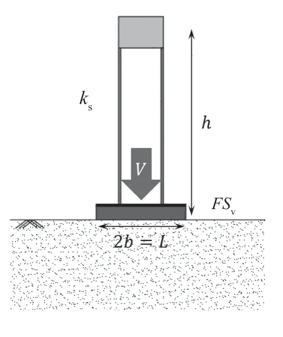
Fig. 5 Converted target structure-foundation system
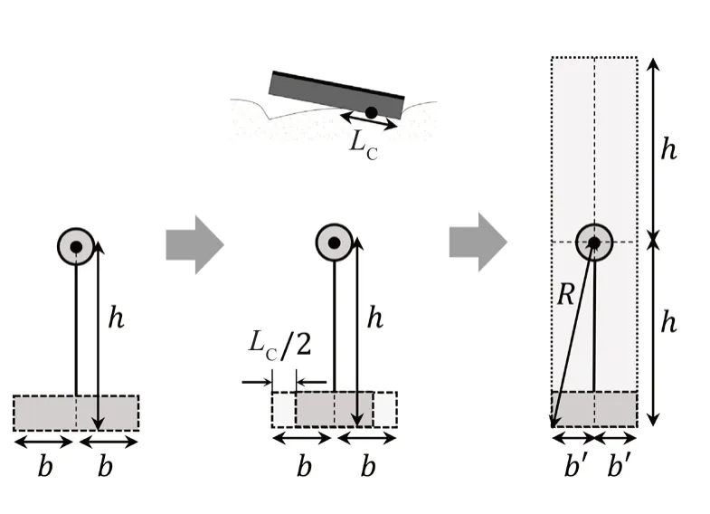
Fig. 6 Conversion of dimensions of SDOF structure on rocking foundation system to Housner rocking model
The dynamic centrifuge test results of previous studies (Koet al., 2018a, 2021) are used to validate the analytical methods. The structure and foundation models used for the previous centrifuge tests comprise two thin steel plates, a lumped mass on top of the structure, and a thin supporting plate that is fixed to the aluminum square foundation model with bolts, as shown in Fig.5. It was assumed that the structural dynamic response of the model in the present study remained in the linear elastic range during strong shaking. Tables 2 and 3 summarize the properties of the test models of Koet al.(2018a) and Koet al. (2021), respectively. Six types of earthquakes (Ofunato, Hachinohe, Northridge, Sweep,Sine 4 Hz, Sine 2 Hz) were used and at least 30 seismic waves were inputted for each centrifuge test model.The intensities of the input motions were increased in stages from small to large. The specific descriptions of the previous centrifuge tests and models are provided in Koet al. (2018a) and Koet al. (2021). As stated by Gavraset al. (2020), the height of the structure models is considered as the height of the lumped mass. The properties of the centrifuge test models utilized by Koet al. (2021) are used to predict the rocking behavior of the foundation using the method in the Housner model and the conventional SFSI governing equation (Eq. (5))of the rocking-dominated 2DOF system. The predicted rocking behavior of the foundation is compared with the rocking behavior of the foundation measured through the dynamic centrifuge tests. Moreover, the properties of the centrifuge test models utilized by Koet al.(2018a) are used to calculate the maximum rotation of the rocking foundation during an earthquake, and this rotation is compared with the rotation angle measured via the dynamic centrifuge tests.
4.1 Prediction of foundation rocking behavior using conventional SFSI governing equation
For a givenu˙g˙ obtained from the centrifuge freefield motion, the SFSI governing equation of the rocking-dominated 2DOF system (Eq. (5)) is expressed as a first-order differential equation using the state space representation as follows:

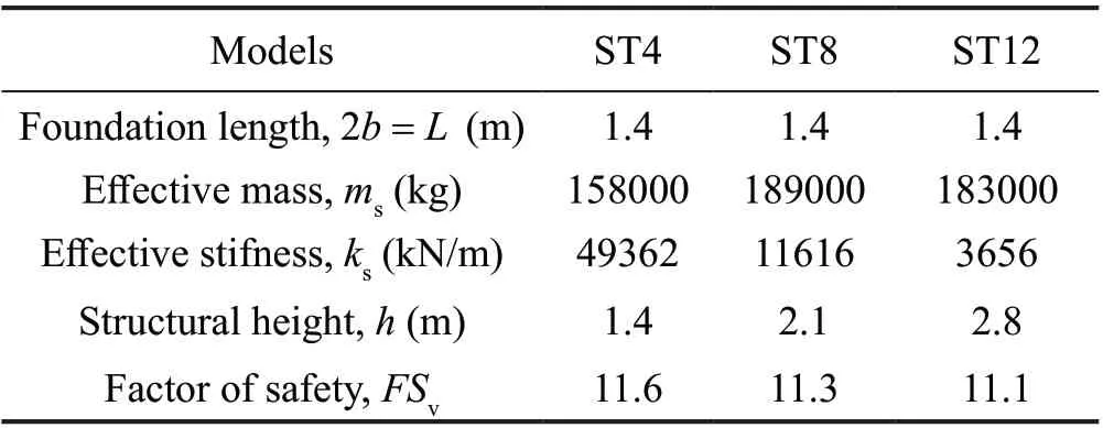
Table 2 Properties of centrifuge test models used in a previous study (Ko et al., 2018a) at prototype scale
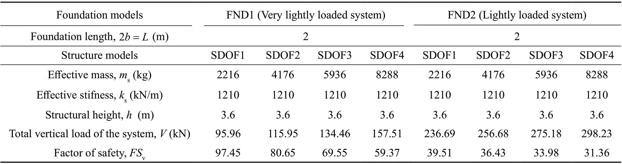
Table 3 Properties of centrifuge test models used in a previous study (Ko et al., 2021) at prototype scale
Finally, the response matrix,X, can be expressed as a first-order differential equation:
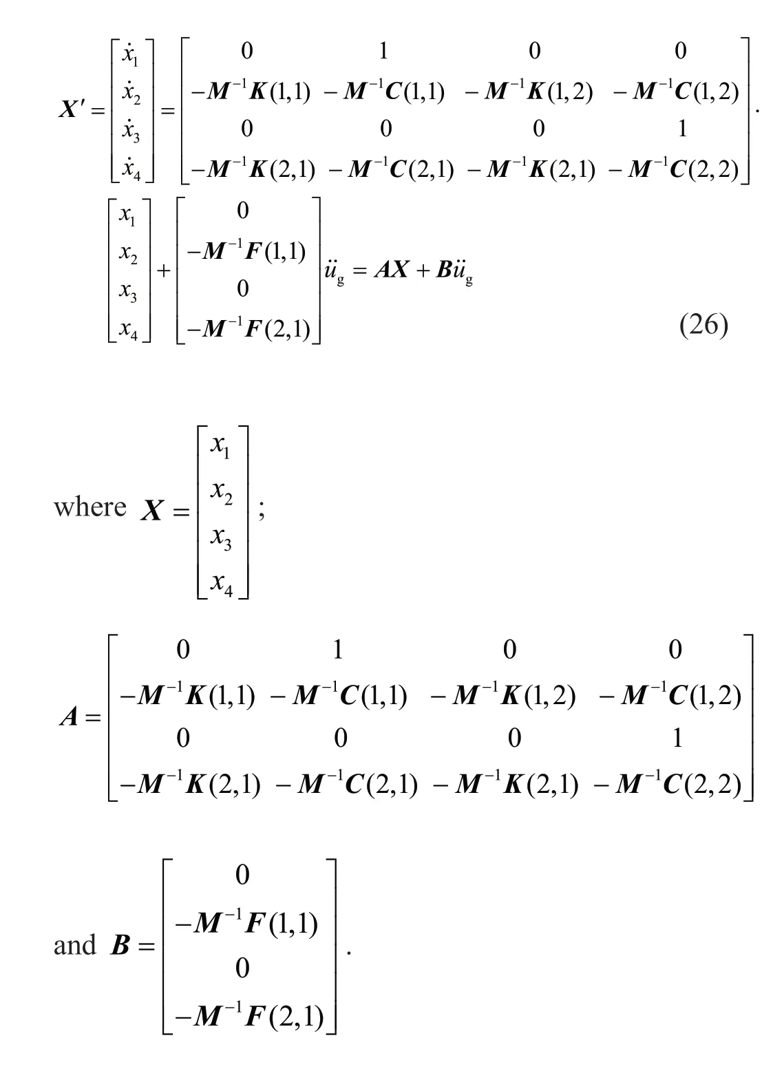
Here,u˙g˙ is obtained as discrete time step data from the centrifuge test results. The continuous time dynamic system, which is a function of matricesAandB, can be converted into a discrete time dynamic system withAdandBdusing the continuous to discrete time (c2d)command in MATLAB. The conversion using the c2d command is explained in Kimet al. (2020). Given that the initial condition ofXis [0; 0; 0; 0], the system response at time step (i+1) can be expressed as follows:

During an earthquake, the shear modulus of soil decreases as shear strain increases. To reflect the nonlinear characteristics of the shear modulus for calculating foundation stiffness, FEMA 356 has suggested the effective shear modulus ratio for various site classes according toVs30(Table 4) and the peak ground acceleration (PGA) at the soil surface, as shown in Fig. 7. The ground model of Koet al. (2021)corresponds to an E site with aVs30of less than 182 m/s.
According to the PGA at the surface, the effective shear modulus ratio is applied to calculatekθ. The rotation of the 2DOF system is predicted using the SFSI governing equation by calculating rotational stiffness using the FEMA 356 stiffness and assuming the damping ratios of structural and foundation rotational damping as 5% which does not reflect the nonlinearity of damping for the foundation-structure system. The recorded data of the Ofunato, Hachinohe, and Northridge earthquakes are used in the centrifuge tests. The detailed calculation for the test models and the description of the earthquake signals and centrifuge tests are provided in Koet al.(2021).
Figure 8 shows the time history of the measured and predicted rotational responses of the foundation with SDOF2 during weak and strong earthquakes (weak earthquake: Hachinohe, surface PGA: 0.14 g; strong earthquake: Ofunato, surface PGA: 0.66 g). The predicted time history of rotation is estimated from the conventional SFSI governing equation of the 2DOF system. Two accelerometers attached at the edge of the foundation are used to measure the dynamic rotation of the foundation during an earthquake. During a weak earthquake, the predicted rotational response is considerably larger than the measured rotational response. Furthermore, there is a phase difference between the predicted and measured rotational responses; the period of the predicted rotational response is longer than that of the measured rotational response. The absolute values of the predicted and measured maximum rotation are 0.00415 rad and0.00107 rad, respectively. The impedance functions for the foundation (frequency-dependent stiffness and damping) are not considered, and 5% damping of the foundation-structure system is used for solving the SFSI equation. Therefore, those two limitations would lead to overestimating the foundation rotation during a weak earthquake. During a strong earthquake, the phases of the predicted and measured rotation are considerably more similar compared to the weak earthquake. Moreover,since the shear modulus reduction is considered for determining the foundation stiffness, the absolute values of the predicted and measured maximum rotation are similar.

Table 4 Varioussiteclassesaccordingto Vs30 for effective shear modulusratio (FEMA 356)

Fig. 7 Effective shear modulus ratio for various site classes and surface PGA
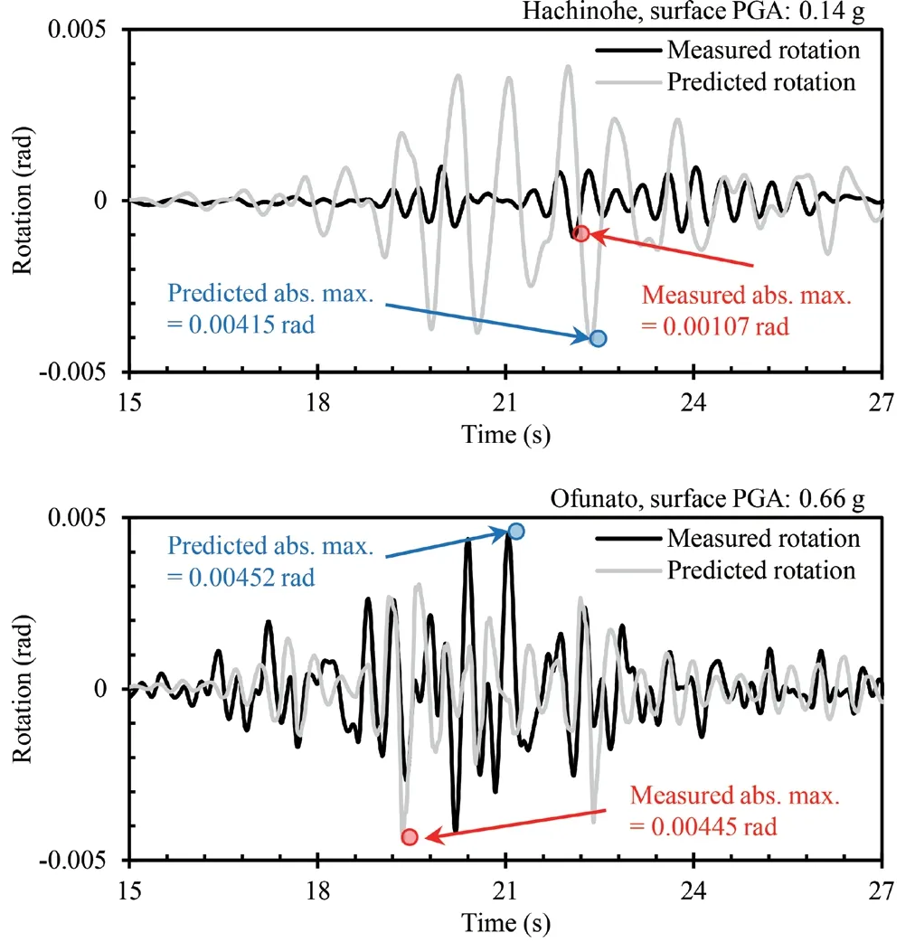
Fig. 8 Time history of measured and predicted rotational response of foundation combined with SDOF2 during weak and strong earthquakes (time history of rotational response is predicted from the conventional SFSI governing equation of the 2DOF system using centrifuge data by Ko et al. (2021))
Figures 9 and 10 clearly show the trends of the predicted rotation vs. the measured rotation. Figure 9 depicts the measured and predicted maximum rotation of the foundation during the earthquake for the SDOF1,SDOF2, SDOF3, and SDOF4 testing models of Koet al. (2021). The difference between the predicted and measured maximum rotation is significant during the weak earthquake (small rotation), but the difference decreases as the maximum rotation increases. In contrast,the difference decreases as the structural height of the testing model increases (i.e., a large amount of data for SDOF4 is on 1:1 line). This is because the foundation tends to exhibit more rocking compared to sliding as the foundation-structure system becomes more slender.Therefore, the SFSI governing equation of the 2DOF system without sliding can accurately predict the maximum rotation of the slender foundation-structure system.
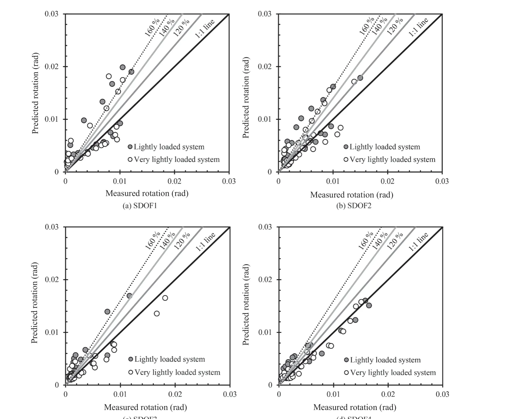
Fig. 9 Measured and predicted maximum rotation of foundation during earthquakes: (a) SDOF1; (b) SDOF2; (c) SDOF3; and(d) SDOF4 (i.e., maximum rotation is predicted from the conventional SFSI governing equation of the 2DOF system using centrifuge data by Ko et al. (2021))
Figure 10 shows the ratio of the predicted and measured maximum rotation of the foundation vs. the PGA at the surface. When the PGA at the surface is less than 0.2 g, the values of the ratio are scattered from 0.6 to 7, but they converge to 1 as the PGA at surface increases. Although FEMA 356 suggests the effective shear modulus ratio according to PGA, which can reflect the nonlinearity of foundation stiffness, the variation in foundation stiffness within a small range of strain (weak earthquake) cannot be reflected using the effective shear modulus ratio. Consequently, the maximum rotation can be predicted through the conventional SFSI governing equation during a strong earthquake but not a weak earthquake. However, the prediction of the maximum rotation using the conventional SFSI governing equation requires considerable information about the soilfoundation-structure system, such as structural mass and stiffness, foundation mass and stiffness, and the shear modulus ratio of soil.
4.2 Prediction of foundation rocking behavior using Housner rocking model
As previously discussed, the prediction of the maximum rotation of the foundation during an earthquake using the Housner rocking model requires a few parameters of the foundation-structure system:effective structural stiffness (ks), structural height (h), the total vertical load of the system (V), the vertical factor of safety of the system (FSv), and foundation length (L).
Figures 11 and 12 show the measured and predicted maximum rotation of the foundation during the strong earthquake. The maximum rotation is predicted using the Housner rocking model and centrifuge data by Koet al. (2021) and Koet al. (2018a), respectively. The method can predict rotation using the Housner rocking model when the rocking foundation is after the yield state, which indicates that the maximumModuring an earthquake is equal toMult. The proposed method cannot predict the maximum rotation during the weak earthquake. Accordingly, the number of data points in Fig. 11 is less than that in Fig. 9. The accuracy of the method for predicting the maximum rotation is lower than that of the conventional SFSI governing equation.The maximum rotation predicted using the method exhibits good agreement with that obtained using the centrifuge data of Koet al. (2018a) (Fig. 12). As Gajan and Kutter (2008) stated that the rocking foundation can be optimized whenL/LCis close to 10, the predicted rotation and the rotation measured using the centrifuge model whoseFSvis close to 10 exhibit relatively better agreement corresponding to the models of Koet al.(2018a) compared to the models of Koet al. (2021).
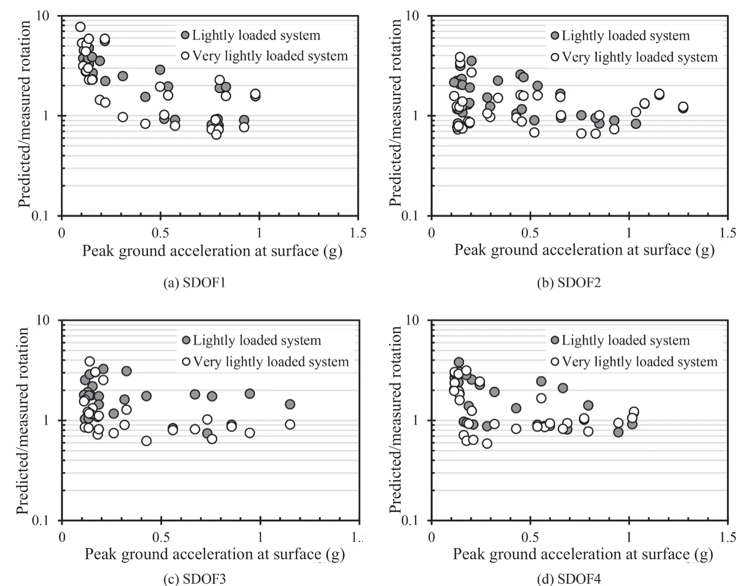
Fig. 10 Ratio of predicted and measured maximum rotation vs. peak ground acceleration at surface: (a) SDOF1; (b) SDOF2;(c) SDOF3 ; and (d) SDOF4 (i.e., maximum rotation is predicted from conventional SFSI governing equation of 2DOF system using centrifuge data by Ko et al. (2021))
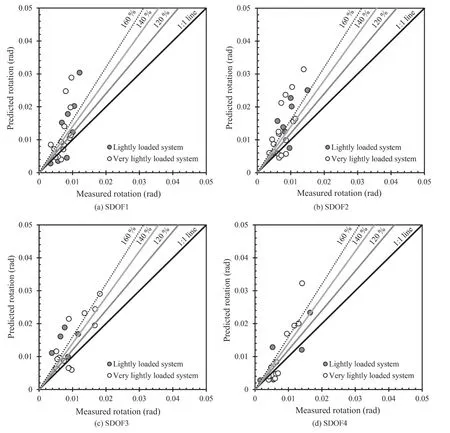
Fig. 11 Measured and predicted maximum rotation of foundation during earthquakes: (a) SDOF1; (b) SDOF2; (c) SDOF3; and(d) SDOF4 (maximum rotation is predicted using Housner rocking model and centrifuge data by Ko et al. (2021))
5 Conclusions and limitations
The performance of a rocking foundation, particularly rotation, during an earthquake must be evaluated to apply the foundation in practice. The analytical models for SFSI are advantageous, because these models can provide approximate solutions of dynamic response for the foundation-structure and provide insight about the SFSI effects on dynamic rocking behaviors. Therefore,to evaluate the rocking behavior of the foundation during earthquakes, two representative analytical models have been introduced: conventional SFSI model and Housner rocking model. In this study, the representative analytical models, which can both estimate the rocking behavior of the foundation, were evaluated and validated with the dynamic centrifuge tests. The conventional SFSI governing equation of the rocking-dominated 2DOF system, which can evaluate the dynamic response of foundation rotation, requires considerable information about soil-foundation-structure systems. In contrast,the modified Housner rocking model requires a few parameters: effective structural stiffness (ks), structural height (h), total vertical load of the system (V), vertical factor of safety of the system (FSv), and foundation length (L). However, the method using Housner model is appropriate for strong earthquakes because the yield state of foundation rocking behavior is reached. The main findings of this study are as follows:

Fig. 12 Measured and predicted maximum rotation of foundation during earthquakes (maximum rotation is predicted using Housner rocking model and centrifuge data by Ko et al. (2018a))
(1) The conventional SFSI governing equation can predict the maximum foundation rotation during a strong earthquake. However, the predicted rotation was larger than the rotation measured from the centrifuge test results during a weak earthquake. Foundation stiffness varies significantly within the small strain range of a weak earthquake. However, this characteristic could not be reflected by applying the effective shear modulus ratio according to the PGA at the surface.
(2) The maximum rotation predicted by the method using the Housner rocking model exhibited good agreement with the maximum rotation measured through the centrifuge tests. In addition, if the foundationstructure system was a rocking-dominated system with a large slenderness ratio, the maximum rotation predicted by the method was close to the actual maximum rotation during an earthquake.
(3) Although the accuracy of the method using the Housner model for predicting the maximum rotation was lower than that of the conventional SFSI governing equation, the Housner model was able to predict the maximum rotation using a few parameters.
The following are the limitations of this study.
(1) The foundation rocking stiffness for solving the conventional SFSI model did not reflect the frequency dependency parameters (impedance function), which could significantly affect the dynamic response of the SFSI system within the elastic regime (small strain)during weak earthquakes.
(2) Although the nonlinearity of the shear modulus ratio of soil depending on the strain level was reflected by using the effective shear modulus ratios, 5% damping was used to solve the conventional SFSI equation without considering the nonlinearity of damping.
(3) The validated structure models were lighter than the foundation models and the friction angle of the tested sand was large, so that the vertical factors of safety of the validated centrifuge test models were significantly large. In the future, to reflect practical conditions, the analytical models should be validated with the heavily loaded systems.
Acknowledgement
This work was supported by the National Research Foundation of Korea (NRF) grant funded by the Korean Government (Ministry of Science and ICT) (No.2017R1A5A1014883).
杂志排行
Earthquake Engineering and Engineering Vibration的其它文章
- A review of the research and application of deep learning-based computer vision in structural damage detection
- Experimental study of vertical and batter pile groups in saturated sand using a centrifuge shaking table
- Effect of geofoam as cover material in cut and cover tunnels on the seismic response of ground surface
- Dynamic response of concrete face rockfill dam affected by polarity reversal of near-fault earthquake
- Analyzing uncertainties involved in estimating collapse risk with and without considering uncertainty probability distribution parameters
- Theoretical and experimental studies on critical time delay of multi-DOF real-time hybrid simulation