A general model for trailing edge serrations simulation on wind turbine airfoils
2021-09-17HuijingCaoMingmingZhangYinanZhangTengZhou
Huijing Cao ,Mingming Zhang ,d,∗,Yinan Zhang,Teng Zhou
a Institute of Engineering Thermophysics,Chinese Academy of Sciences, Beijing 100190, China
b The Key Laboratory of Wind Energy Utilization of CAS, Beijing 100190, China
c University of Chinese Academy of Sciences, Beijing 10 0 049, China
d Dalian National Laboratory For Clean energy, Chinese Academy of Sciences, Dalian 116023, China
ABSTRACT Trailing edge serrations (TESs) are capable of noticeably suppressing the turbulent trailing edge noise induced by rotating wind turbine blades and become an integral part of a blade.However,the challenges involved in the dimensional design of serration height 2 h,wavelength λ and flap angle ϕ are yet to be dealt with in a satisfactory manner.To address the problem,a general model for simulating the effects of serrations on the hydrodynamic and aeroacoustic performance is proposed due to its ease of use and relatively low requirements for user input.The solid serrations are replicated by momentum sources calculated by its aerodynamic forces.Then,a case relevant to wind turbine airfoil is examined,a hybrid improved delay detached eddy simulation (IDDES) method coupled with FW-H integration is deployed to obtain the flow features and far-field sound pressure level.It is found that the modeling method could reproduce the flow field and noise as serrated airfoil.
Keywords:Wind turbine airfoil Trailing edge serrations Trailing edge noise Modeling method
The aeroacoustic noises caused by blade rotating at high wind speed are prominent and are the main noise source of a wind turbine [1] .As the wind turbines are becoming nearer to residential areas,complaints from local people are also becoming more universal,which brings great economic loss to turbine operators.More severely,the noise produced by blades has a negative influence on local residents’ life.Besides,in order to address the noise problem,the tip speed is often restricted during the process of blade design,negatively influencing the power output of wind turbine.
Therefore,it becomes increasingly important and urgent to resolve the aeroacoustic noise problem of wind turbine blade.The wind turbine airfoil,as the basic aerodynamic element of blades,plays a dominated role in the generation of aeroacoustic noise.For this purpose,effective measures are needed to be adopted to suppress the aerodynamic noise of the airfoil.In recent years,the novel trailing edge serrations (TESs),inspired by the silent owl wing,have received extensive attention in terms of effectiveness,cost,production,and installation.Undoubtedly,this bionic configuration may solve the aforementioned aeroacoustic problems of large-scale wind turbine blades.
In recent years,a large number of experimental and numerical results showed that the TESs installed on the two-dimensional airfoils achieved remarkable reduction effect and were gradually put into application on the three-dimensional wind turbines blades.Oerlermans et al.[2,3] firstly applied the serrated trailing edge technique to a 2.3 MW wind turbine with an impeller diameter of 96 m.Field measurement found that blades with serrated trailing edges can reduce noise by about 3 dB compared to the baseline blade.Lee and Lee [4] installed TESs on a 10 kW wind turbine,and achieved significant noise reduction of up to 5 dB(A) in field tests,which was attributed to the suppression of trailing edge bluntness noise by serrations.Lately,Ryi and Choi [5] measured the noise of a 10 kW wind turbine model in the acoustic wind tunnel.It was observed that noise reduction frequency was in the range of 400 Hz to 6 kHz and skewed serrations were superior to normal serrations by achieving extra 0.5 dB noise reduction.
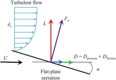
Fig.1.Sketch of the turbulent flow passing a serration.
Although the application of the TESs has achieved satisfying noise reduction effects,the selection of the size is only based on experimental experiences,lack of optimization design methods to fully exert its advantages in terms of noise reduction.The primary cause is lack of a modeling method to replicate the serration effects on the aerodynamic noise and flow field.To this end,based on the two-dimensional symmetrical NACA0018 airfoil at low Reynolds number,a novel modeling method [6] was previously developed by replacing solid serrations with momentum sources,which was capable of reproducing the flow field results affected by serrations.However,the asymmetrical structure of the wind turbine airfoil operated at the high Reynolds number leads to the flow field characteristics being quite different from the previous airfoil.Therefore,it is necessary to improve previous modeling method to be adapted to high Reynolds number and apply it on the wind turbine airfoils to study the noise reduction effect of serrations.
To authors’ knowledge,this paper firstly utilized the computational fluid dynamics method to estimate the aerodynamic noise produced by serrated airfoils at high Reynolds number.The improved delay detached eddy simulation (IDDES) method was used to obtain the instantaneous turbulent information in the flow field and the Ffowcs Williams-Hawking (FW-H) acoustic analogy method was deployed to predict the aerodynamic noise.And the current work focuses on the accuracy of the developed modeling method and studies the effects of serrations on the flow field and aeroacoustics.
Thus,this study utilized the improved modeling method to simulate the flow field and predict the noise,which was benchmarked against the fully resolved serrated airfoil.
The core behind the modeling method is to replace the solid serration by adding the momentum source terms,so as to replicate the flow field affected by serrations.The key point of the method is to accurately obtain the aerodynamic forces (mainly lift and drag force).Therefore,the lift prediction formula for serrations proposed by Llorente and Ragni [7,8] is used in the manuscript.The linear thin airfoil theory is adopted to integrate the lift coefficients of serrations,which can be formalized by the following equation:

where theβ,candlsdenote the angle between the TES and the local velocity vector,the airfoil chord and the effective length of serrations.With Eq.(1),the lift coefficient of serrations can be easily predicted and agrees well with the numerical [7] and experimental [8] data.By the orthogonal decomposition,the pressure drag coefficient can be obtained byCdpressure=Cl·tanα.In addition,the classical boundary layer theory [9] is used to predict the viscous drag for turbulent flow passing the serrations.Fig.1 shows the sketch of the turbulent flow passing the flat-plate serration.To simplify the model,the flow passing the upper and lower surface of the serrated airfoil can be approximated as fully developed turbulent flow past a flat plate.Thus,when the Reynolds number is below 6×10⁶,the friction drag coefficient at a fixed stream-wise location can be expressed as [9]:

wherelrepresents the flow distance.The total drag coefficient is calculated by integrating the length and width over the serration surface of two sides,which can be written as

It is noticed that the estimation method for the aerodynamics of serrations is not fixed,which may change with the flow condition and can be replaced by more accurate estimation formula.
In a finite volume context,the total force acting on the fluid is expressed by:


whereViis the grid cell volume.The momentum equation at each cell where the model is applied can be expressed by:

This study is mainly focused on the flow characteristics of serrated airfoil at high Reynolds number,which requires a huge amount of grid.The IDDES [10],a hybrid modeling approach that combines features of Reynolds-averaged Navier–Stokes (RANS)simulation and large-eddy simulation (LES) method,provides a more flexible and convenient scale-resolving simulation model and is suitable to solve complex turbulent flows around the wind turbine airfoil at high Reynolds number [11,12].
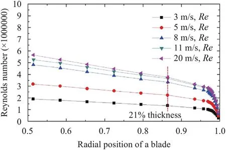
Fig.2.Operating condition of referenced sections of a 1.5 MW horizontal axis wind turbine [13].
The governing equations of the shear stress transport (SST) IDDES model can be written as:

Here,k,μ,μt,τijandSijdenote the turbulent kinetic energy,molecular viscosity,turbulent viscosity,stress tensor and strain tensor,respectively.The IDDES length scale in Eq.(8) reads as follow:

where
lRANS:length scale of RANS method,constantCμ=0.09;ωrepresents the specific dissipative rate;
lLES:length scale of LES method,CDESΔ;theΔdenotes the grid length scale;
fb:the elevating-function,which is aimed at preventing the reduction of the RANS Reynolds stresses,and the details are presented in Ref.[10].
A wind turbine with variable speed and pitch control [13] is selected as a reference and its detailed information is shown in Table 1.The Reynolds number distribution along the blade calculated by the blade element theory (BEM) is shown in Fig.2.According to the field noise measurement results [1],the prominent noise of the wind turbine is mainly centered at the span-wise location of 80%-90% of the blade,where it is an airfoil with a thickness of 21%.It is found that the operating Reynolds number is around 3×10⁶when reaching the rated wind speed.
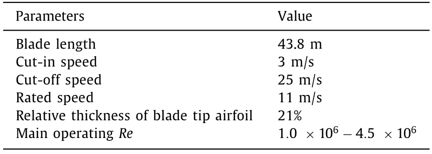
Table 1 Operating condition of a reference 1.5 MW horizontal axis wind turbine.

Table 2 The aerodynamic forces of experimental and numerical results.
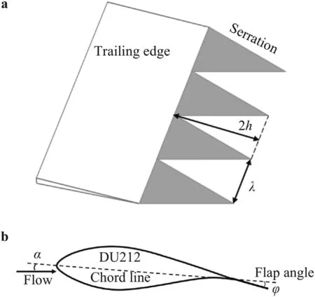
Fig.3.Parameters of the serration geometry. a Sketch of the trailing edge serration. b Serrations with flap angle.
To this end,the DU212 airfoil with high aerodynamic performances developed by Delft University is chosen in this manuscript.In order to study the noise characteristics at the rated wind speed,the Reynolds numbers of 3×10⁶is selected for the research.Meanwhile,the airfoil near the tip of the blade operates at small angles of attack,so the angle of attack in the manuscript is chosen 2◦and this flow condition is completely consistent with Pires’ experiments [14].According to the noise reduction law for serrations proposed by Gruber et al.[15],a serration size with 2h/c=0.15 andλ/(2h)=0.5 is selected to satisfy the noise reduction criterion.Due to the deflection angle at the trailing edge of the wind turbine airfoil,the flap angle of the serration is not installed horizontally.Experiments by Vathylakis et al.[16] showed that,when the flap angle coincided with the deflection angle of the airfoils,it is more conducive to noise reduction.Therefore,the flap angle installed at the serration is set at 5◦and the sketch of serrated airfoil is shown in Fig.3.The origin was set at the central location of the trailing edge.Thex-axis is aligned with the stream-wise direction;thez-axis coincides with the airfoil trailing edge.
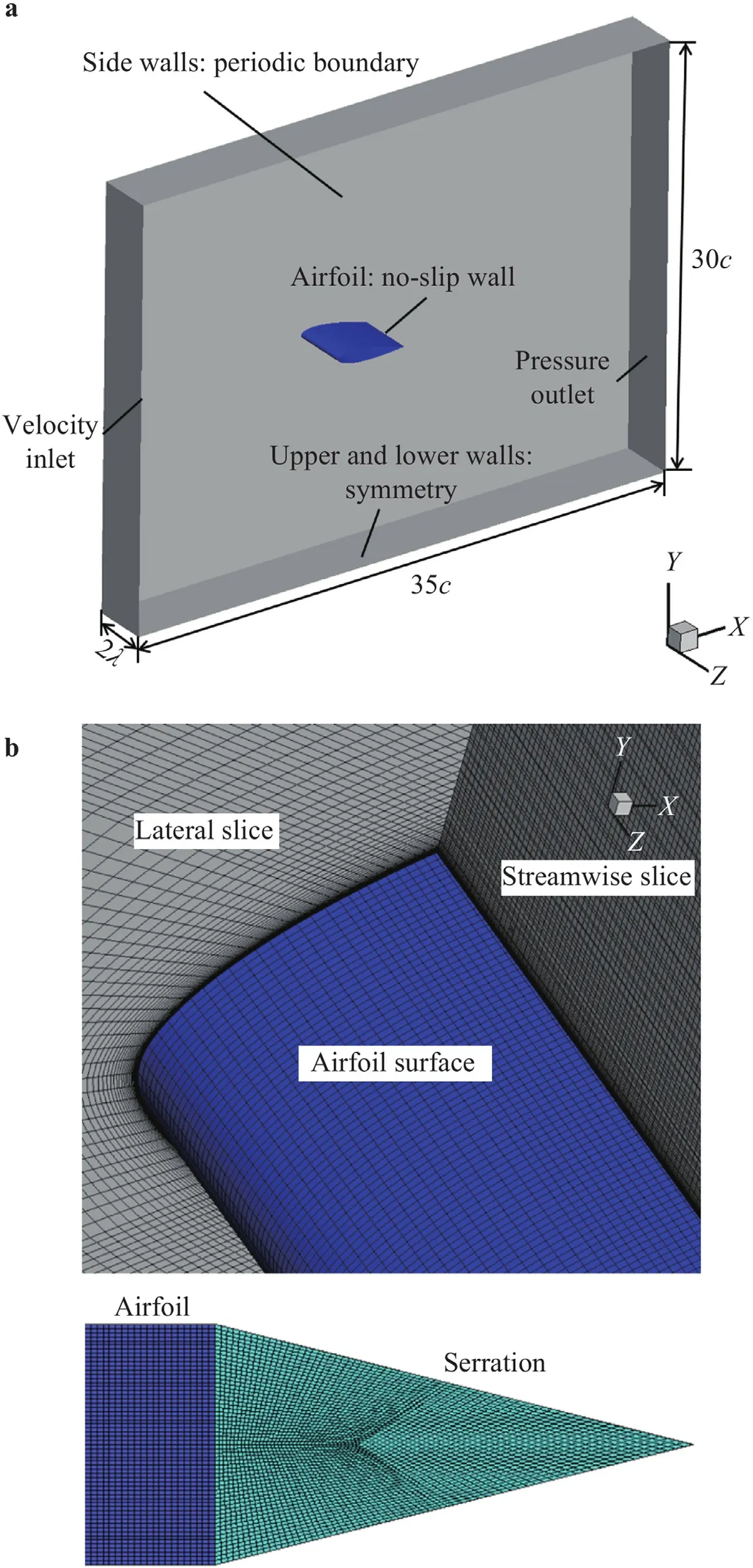
Fig.4.Sketches of computational mesh system. a Sketch of computational domain. b Mesh around the airfoil and serration.
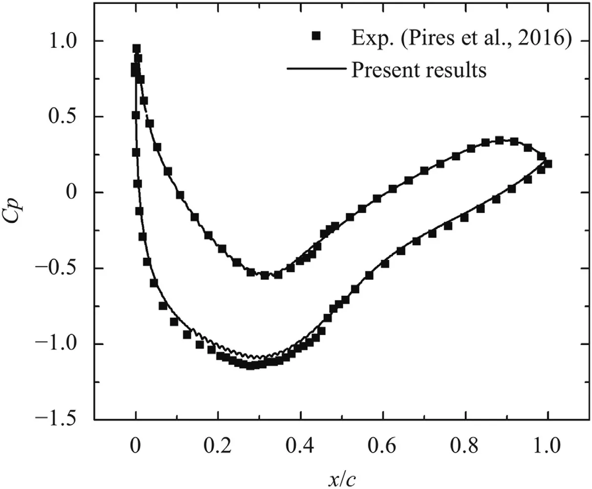
Fig.5.Distribution of static pressure coefficient along chordwise direction.
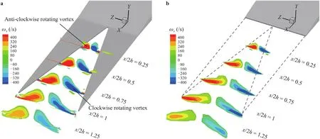
Fig.6.ωx contours of virtual and physical TES. a Physical TES. b Virtual TES.
Figure 4a indicates the sketch of computational domain,a rectangle domain is built up.The inlet is placed 15caway from the airfoil,and the outlet is placed 20cdownstream of the airfoil.A C-type topological structure around the airfoil is adopted and the mesh node is clustered near airfoil surfaces by a geometric expansion.The dimensions of the first layer grids in three directions areΔymax=0.015 mm,Δxmax=2 mm andΔzmax=2 mm.Eventually,the structured grid system withΔy+<1,Δx+<100,Δz+<100 and the growth ratio=1.1 is chosen,satisfying the requirement for IDDES simulation recommended in Ref.[17].Figure 4b illustrates the lateral and stream-wise slices of the surface mesh as well as the mesh of the TES.The structural mesh of the physical TES is divided by a Y-type topology,and the mesh density of the TES is close to that of the airfoil surface,so that grid resolution at the surface of TES could remain the same as the airfoil surface.Consequently,overall amounts of grids for the baseline and serrated airfoils are 1.2 and 1.8×10⁷,respectively.In the IDDES simulation,pressure-based solver coupled with the semi-implicit method for pressure linked equations (SIMPLE) velocity scheme was employed.The pressure and momentum were discretized with the secondorder and central difference scheme,and the second order implicit scheme was adopted in the time discretization.The time step was set small enough at 2×10⁻⁵s to ensure the Courant number was less than 1.
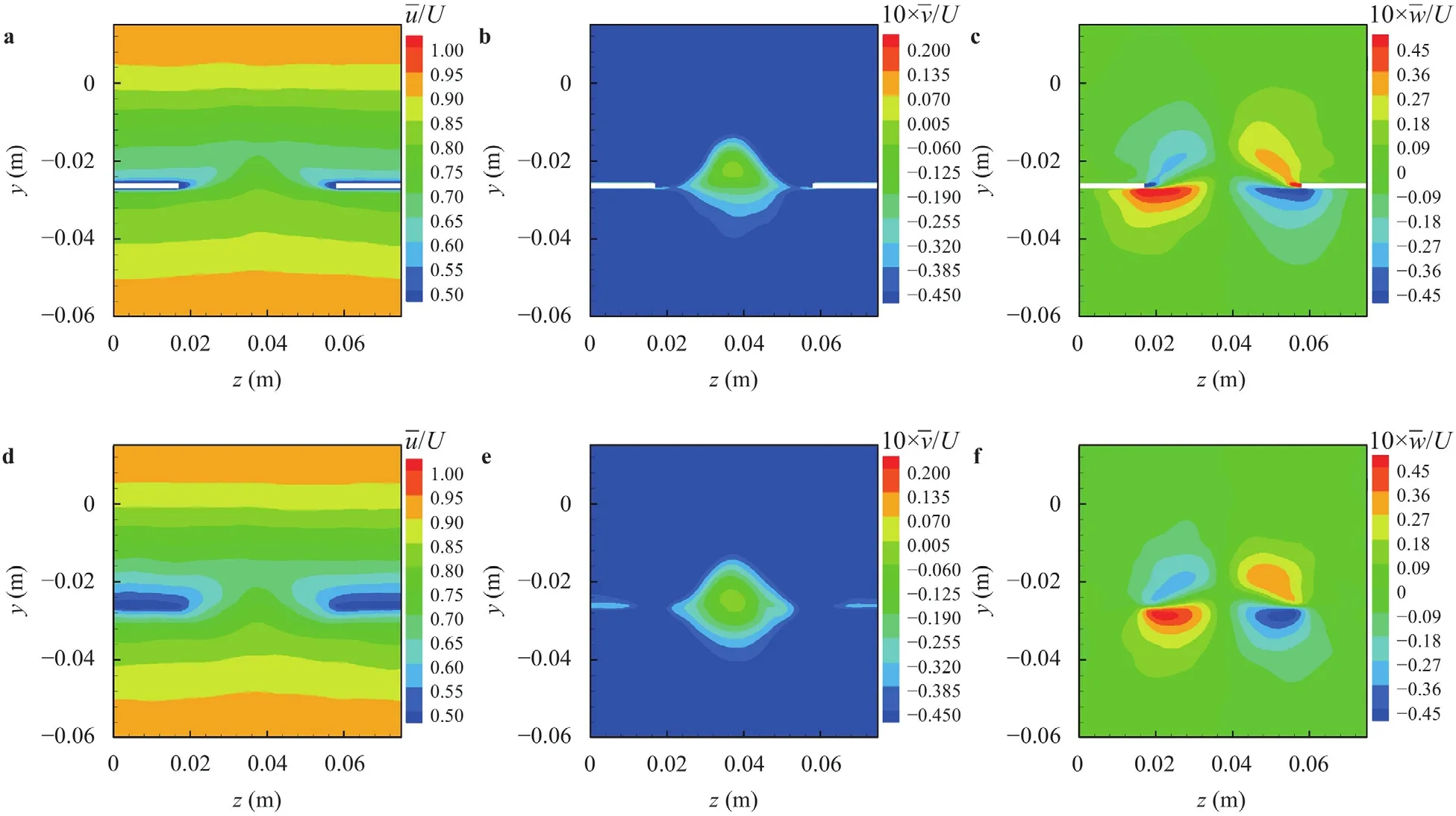
Fig.7.Contours of time-averaged velocity components of the virtual and physical TES at x/ (2h)=0.5.a Mean u of physical TES.b Mean v of physical TES.c Mean w of physical TES. d Mean u of virtual TES. e Mean v of virtual TES. f Mean w of virtual TES.
Deploying above methods,the hydrodynamic and aeroacoustic parameters of baseline and serrated airfoils are obtained.To validate the accuracy of our simulation method,the numerical results are compared with experimental result [14].Figure 5 displays the comparison of the distribution of static pressure coefficient along chord-wise direction whenα=2◦andRe=3×10⁶.The numerical results from present model and the experimental results are presented,where the static pressure coefficient is defined asCp=(p−pr)/(0.5ρU2),wherepandprdenote the wall pressure and static pressure.Clearly,the computational results are in good agreements with experimental ones [14].From another aspect,the aerodynamic forces at the same Reynolds numbers and angle of attack are listed in Table 2.Actually,the lift and drag coefficients are coincident with those of experimental study.Sufficient comparisons of the pressure coefficient and aerodynamic forces suggest that the IDDES results in this manuscript are reliable.
As illustrated in Ref.[6],a pair of stream-wise vortex with opposite rotating directions is detected,which is attributed to the pressure gradient between the suction and pressure side.Figure 6a shows the distribution of the stream-wise iso-vorticity(ωx=∂w/∂y−∂v/∂x) contours at different stream-wise locations.It is shown that the vortex is generated at the serration root and then developed along the serration edge.As the vortex leaves the serration,it sheds along the stream-wise direction and its strength gradually decreases due to the dissipation.The contours of the stream-wise vorticity obtained from the modeling method are presented in Fig.6b.To intuitively detect the location of the vortex,the edge of the serration is plotted with dotted lines.It is shown that iso-vorticity contours of the virtual TES are in good agreement with that of the airfoil with physical TES.The strength of the vortex between serrations is identical to the shedding vortex from solid serration,further verifying the accuracy of the modeling method.Moreover,both the span-wise and vertical locations of vortex cores are also captured accurately by the new model.The modeling method could replicate the process of vortex production,evolution and dissipation due to viscosity and convection with the vortex from the upstream boundary layer.
The contours of the time-averaged velocity components for the serrated airfoil at the middle slice of the serrationx/(2h)=0.5 are presented in Fig.7a-7c.It is found that the flow field near the trailing edge is greatly altered by the counter-rotating vortex.Driven by the pressure gradient between two sides,the fluid at the pressure side is rolled along the serration edge to the suction side,which generates an upward flow and eventually uplifts the boundary layer in serration gaps.Meanwhile,a complex distribution of thezvelocity between the serration is detected in Fig.7c.Specifically,on the pressure side,the fluid shrinks to the serration gap and exhibits an inward motion.On the suction side,the transported fluid is scattered to the serration edge and displays an outward motion.All these motions are driven by the counter-rotating vortex,resulting in the opposite span-wise motion between two sides.The contours of the velocity components obtained by the modeling method at the same locations are shown in Fig.7d-7f.It is observed that the modeled velocity contours are basically the same as that of serrated airfoil,suggesting that the proposed modeling method is high in precision.
In order to quantitatively assess the precision of the model,the profile of time-averageduandvvelocity distribution parallel toyaxis atz=0.0375 m is plotted in the Fig.8.It is noticed that the deficit ofxvelocity at the serration root is obviously reduced when installing serrations.The cause contributing to the phenomenon is that the induced stream-wise vortex strengthens the energy exchange between the pressure and suction side and eventually reduces the deficit.As shown in Fig.8b,the upward flow is observed at the serration root,which enhances the fluid mixture between two sides.It is assumed that the reduction the trailing edge noise is associated with the upwash [6],which breaks up the large-scale vortex structures shedding from the upstream turbulent boundary layer,thereby suppressing the noise at the low-to-moderate frequency presented in Fig.9.Likewise,it is found that the velocity profile obtained by the modeling method almost coincides with the solid serration,quantitatively proving that the modeling method is suitable to replicate the flow field of serrated airfoils under high Reynolds number.
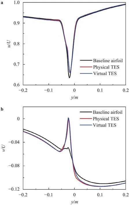
Fig.8.Comparisons of mean u and v at serration root z=0.025 mm. a Mean u. b Mean v.
The time domain sound pressure signal at the detection point can be obtained by solving the FW-H integral equation [18],and then the spectrum of the noise can be derived by the FFT analysis.The detection point is set above the trailing edge by a distance of 2c.The spectra of sound pressure level (SPL) for the baseline airfoil,physical and virtual TES are shown in Fig.9.It can be seen that the noise spectrum of the wind turbine airfoil under high Reynolds number presents a broadband characteristic.With the TESs installed,significant noise reduction at the frequency ranging from 1000 Hz to 3000 Hz is detected,and the noise spectrum calculated by the above modeling method is in good agreement with that of the physical TES.The directivity of the far-field sound pressure level is given to study the noise reduction effect by the TES at different azimuth angles.As is shown in Fig.10,the arc array with a diameter of 2ccovers an azimuthal angle ranging from -180◦to 180◦and the azimuthal angle between two detection point is 30◦.It can be seen from Fig.10 that the overall sound pressure level(OASPL) of the airfoil presents a radiation characteristic of dipoles,which is specifically characterized by low noise on both sides and high noise on the upper side of the airfoil.With the TES installed,the noise is significantly suppressed and the maximal noise reduction is as much as about 3 dB.Above results indicated that the modeling method can be used for predicting the noise reduction effect of serrations and the accuracy could satisfy the need of engineering applications.
On the whole,based on the above results of velocity,vorticity and noise spectrum,our proposed modeling method is capable of reproducing the flow field and sound pressure level results affected by the serrations.And the error is within the acceptable range of engineering application.With such method,the time and resources for calculating serrated airfoils can be greatly simplified.When simulating the noise reduction effect of different serration sizes or shapes,the method of adding extra momentum sources can omit the process of dividing the grid,which will facilitate the optimal design of the best serration size and speed up the industrial application.
A modeling method for TESs suitable for high Reynolds number is proposed.The solid serrations are replaced by momentum source terms,which could omit the division serration grid.Deploying this modeling method,the hybrid IDDES method coupled with FW-H integration are used to obtain the flow field and the far field sound pressure.
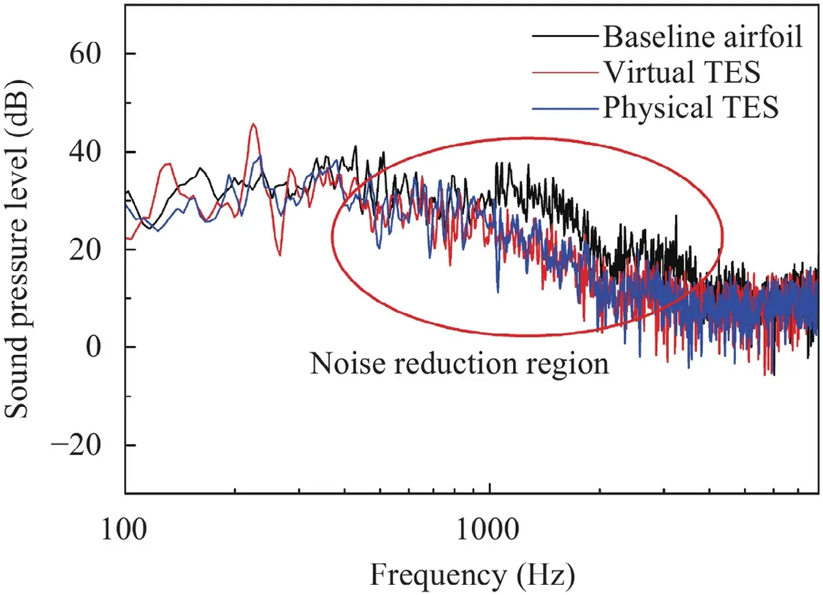
Fig.9.The sound spectra of the baseline airfoil,the virtual and physical TES.
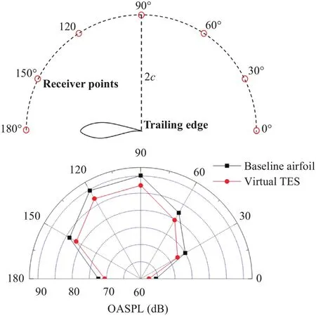
Fig.10.Directivity of the overall sound pressure level.
As revealed from the flow field results,the change of flow field is attributed to the stream-wise counter-rotating vortex.An upwash is formed at the serration gap,which causes the fluid on the pressure surface transported to the suction side,thereby enhancing the energy exchange of the fluid between serrations.All these flow field changes contribute to a noticeable noise reduction at low-tomoderate frequency.Compared with the result of solid serration,it is found that the velocity and vorticity contours calculated by the modeling method are almost the same as solid serration.In addition,the model can accurately predict the noise spectrum of serrated airfoil.
Without the model,the simulation of wind turbine blade with the TESs is very difficult because of the complex grid topology.This modeling method of serrations is a good way to solve the problem,which will promote the industry application of serrated airfoils.
Declaration of Competing Interest
The authors whose names are listed immediately below certify that they have no affiliations with or involvement in any organization or entity with any financial interest (such as honoraria;educational grants;participation in speakers’ bureaus;membership,employment,consultancies,stock ownership,or other equity interest;and expert testimony or patent-licensing arrangements),or nonfinancial interest (such as personal or professional relationships,affiliations,knowledge or beliefs) in the subject matter or materials discussed in this manuscript.
Acknowledgments
This work was supported by the National Natural Science Foundation of China (Grant No.51736008),“Transformational Technologies for Clean Energy and Demonstration”,Strategic Priority Research Program of the Chinese Academy of Sciences (Grant No.XDA21050303).
杂志排行
Theoretical & Applied Mechanics Letters的其它文章
- Simplified permeable surface correction for frequency-domain Ffowcs Williams and Hawkings integrals
- Electrothermal analysis of radiofrequency tissue ablation with injectable flexible electrodes considering bio-heat transfer
- End-to-end differentiable learning of turbulence models from indirect observations
- On the capability of the curvilinear immersed boundary method in predicting near-wall turbulence of turbulent channel flows
- Theory of adaptive mechanical drive
- A 2D numerical ocean model on the Coriolis and wind stress effects using Stochastics
