Design of crashworthy attenuator structures as a part of vehicle safety against impact: Application of waste aluminum can-based material
2021-07-30LksmnWidiPrsetyAdityRioProwoUidillhUidillhIwnIstntoNurAzmhBintiNordin
Lksmn Widi Prsety , Adity Rio Pr owo , ∗, Uidillh Uidillh , Iwn Istnto ,Nur Azmh Binti Nordin
a Department of Mechanical Engineering, Universitas Sebelas Maret, Surakarta 57126, Indonesia
b Agency for the Assessment and Application of Technology (BPPT), Jakarta 10340, Indonesia
c Malaysia-Japan International Institute of Technology - Universiti Teknologi Malaysia, Kuala Lumpur 54100, Malaysia
Keywords: Attenuator structure Waste can Vehicle safety Crashworthiness analysis Impact phenomenon
A B S T R A C T The impact attenuator is an essential system in both race cars and urban vehicles. The structure of an impact attenuator serves as a safety barrier between the impacted surface and the driver in an accident.Attenuator materials tend to have a high price; thus, alternative materials were explored in the current work, i.e., used cans from food and beverage containers. The study deployed a nonlinear finite element algorithm to calculate a series of impacts on the attenuator structures. The thickness of the cans and velocity of the impact were considered as the main parameters. Analysis results concluded that the attenuator’s average energy was 160 0 0 J for a can thickness of 1 mm. This value is more than two times the 0.5 mm thick used cans. The attenuator’s new design was then matched with an attenuator regulation,and the results surpassed the standard value of 7350 J.
The Student Formula is a competition formed by the Society of Automotive Engineers, which aims to challenge students from each university to design and conceptualize small-model formula racing cars. In making this car, protection issues are a significant demand that is very well regulated in the Formula Society of Automotive Engineers [1-3] . Recently, there has been an increasing interest in vehicle safety, which has led to increased research and analysis on the vehicle accident response from experimental trials and simulations [4] . The development of active and passive safety systems that work for passenger safety is also being conducted in the industrial world [5] .
The competition needs every participant to the concept and builds a racecar similar to in the same company. In creating a vehicle, remember to concentrate on the protective factors regulated within the race rules (Formula Society of Automotive Engineers -FSAE Rules). In these regulations, each team must make a safety device called an impact attenuator. Based on these rules, the impact attenuator is declared fit for use to absorb at least 7350 J of energy. The lightweight design will improve the vehicle acceleration performance and fuel economy [6] . An attenuator must be specially made to absorb the collision’s energy—namely the vehicle’s kinetic energy—and reduce the driver’s deceleration acting [7] .The technical requirements of an attenuator are that:
1.The attenuator is set up at the front of a system vehicle with a whole mass of 300 kg, the average and highest deceleration have to be no more than 20 g and 40 g, respectively, while the automobile is traveling at a constant velocity of 7 mm/ms (gstands for gravity acceleration 9.8 m/s2).
2.The entire attenuator absorbed ought to be, as a minimum,7350 J. There also are geometric limitations to the design. The minimum length is 200 mm with a minimal height of 100 mm,200 mm width and maximum distance to the front bulkhead is 200 mm [1] .
3.In impact/collision situations, the attenuator is disallowed to penetrate the front bulkhead while it cannot be a part of bodywork structure. It ought to be securely connected to the front bulkhead [1] .
4.When off-center and off-axis impact/collisions occur, there ought to be sufficient load paths for transverse and vertical loads [8,9] . Furthermore, the policies suggest that the antiintrusion plates has to be inserted to all racing motors and automobile. These may be manufactured from 5 mm robust steel or 4 mm solid aluminum.
5.Vital components, e.g., the critical hoop, battery, and hydraulic reservoir has to be placed behind the bulkhead as they are not allowed on the impact attenuator sector [1] .
In designing an attenuator, the elements that may be considered for fabric dedication include the cost, reliability, weight, and availability [10] . Attenuators are normally manufactured from honeycomb, aluminum, Kevlar, Nomex, aluminum foil, or a combination of the mentioned materials [11-13] . Apart from those materials, different materials, including used cans, are typically manufactured from aluminum and different metal alloys.
Cans are one form of steel waste that is regularly reused and,barring that, may pollute nature. If rust is exposed to water after entering the soil, it will interfere with the soil fertility [14] .Another trouble is the developing use of aluminum for meals and gentle drink packaging [15] . Ordinary aluminum is mixed for added mechanical properties and strength. Cans are composed approximately 92–99% of aluminum, and other minors, e.g., copper,magnesium, silica, manganese [16] .
The purpose of this study is to design an impact attenuator as development effort of vehicle safety. Consideration to reduce the pollution caused by used cans, the waste can-based material is used as material for the proposed design. The design will be analyzed to quantify its crashworthiness against impact/collision. Nonlinear finite element method is used to solve several impact cases in this study.
An impact attenuator that functions as a safety system capable of blocking the surface that is impacted by a driver is a fundamental structure in a formula racing car [11] . This safety system is designed to absorb kinetic energy at the time of impact,which is converted into a deformation that maintains a reasonably low force level and uniform deformation [17,18] . As the deformation occurs unevenly, it will cause a driver to experience a G force.Energy absorption occurs in the form of extensively destroying the structure [19] . Transverse and vertical load paths are provided for the impact attenuator if the impact occurs outside the center axis[20] . The specific energy absorbed and the total energy absorbed can be used to assess the viability of the impact attenuator. The rate of energy dissipation concentrated in a narrow zone is a characteristic of impact attenuators, whereas the structural reminders experience rigid motion [21,22] .
The FSAE rules state that there should be an Anti-Intrusion Plate and Impact Attenuator in the front of the Front Bulkhead,with the Anti-Intrusion Plate in the front of the Impact Attenuator. The Anti-Intrusion plate should be 1.5 mm (0.060 in.) thick of a strong metal material, and 4.0 mm (0.157 in.) thick for aluminum.The Anti-Intrusion Plate should be connected to the Front Seal securely, and for the Anti-Intrusion Plate’s outer profile for the weld joint, the face should be at the centerline of the Front Baffle tube on all sides. The shape should match the Front Bulkhead’s outer dimensions around the rims for bolted joints [1] .
There also are provisions for effect absorbers in which the scale of the Impact Absorbers are at the least 200 mm (7.8 in.) long,with the duration oriented alongside the front/rear axle of the frame. A minimal peak of 100 mm (3.9 in.) and width of 200 mm(7.8 in.) are required for a minimum distance of 200 mm (7.8 in.)in the front of the Front Bulkhead. Finally, they should be attached securely to the Anti-Intrusion Plates or to the Front Seals. It is likewise assumed that the surprise absorber is established on the front of the car with a total mass of 300 kg (661 lbs.), and hitting a concrete effect barrier with a sufficient velocity of 7.0 m/s (23.0 ft/s),should gradually slow down the car to a pace not exceeding a mean of 20 g and a maximum of 40 g. The strength absorbed on this occasion should meet or exceed 7350 J [1] .
Dynamic testing (sledge, pendulum, drop tower, etc.) of the Impact Reducer can be completed in a committed testing facility.While these centers can be a part of a university, they should be supervised by expert personnel or University faculty. Teams are not allowed to construct their own dynamic check kits. Whereas quasistatic testing may be completed through companies using their University centers/equipment, the groups are recommended to exercise warning whilst undertaking testing [1] .
To maintain fuel and enhance the acceleration performance,the Impact Attenuator should be designed with light-weight substances [6] . Typically aluminum, honeycomb, Nomex, carbon composites, or a mixture of those substances are the substances used to make Impact Attenuators to provide the most safely for drivers as they are robust and tend to be light. Tube and plate types, honeycomb systems, trapezoidal truncated shapes, and sandwich systems are examples of effect-soaking systems [11-13] .
The first impact and failure phenomenon concerns occupant protection and particularly pedestrian protection, which has become increasingly important over the years. The reason is inadequate pedestrian safety against severe injuries during a collision with vehicles. To reduce injuries and their severity, design changes in the front structure are required to absorb energy and minimize the force and pedestrians’ acceleration. Therefore, a growing number of energy absorption structures are often designed with different materials, such as highly porous and energy-absorbing foams with plastic deformation behavior, such as egg box structures. The combination of these parts interact under accident loads, for example, the bumper system. For the layout of the new protection system, the deformation behavior and force levels of these "chain interactions" must be predicted [23] .
We concluded that, although the individual modules of materials of different stiffness were excellent to simulate, the adjustment of the parameters of the selected material, as well as the adjustment of the parameters for the calculation of contacts, proved necessary for the interaction—a chain with two or four components to produce a good fit between the simulation and test. The examination approach just described shows its respective limitations for simulation capability, which implies a tremendous importance for interpreting the calculation results. In comparison, there are currently opportunities for more detailed component modeling and new or enlarged material models; testing to verify the simulation results is still necessary to achieve improved prediction accuracy for complex and interacting systems.
The restitution coefficient is a variable that considerably impacts the output fee received to use item collision evaluations.Typically, mathematical–mechanical fashions count on cognition of the numerical values of the restitution coefficients. In exercise, it is predicted that the restitution coefficient’s numerical fee is decided primarily based on experience. This exercise is mainly used within the case of inhomogeneous bodies of complicated shape. One realistic instance is automobile effect evaluation [24] .
The methodological elimination has to be suitable for practical implementation. The reason for this technique is to lessen mistakes within the output of the automobile effect evaluation system.The benefit of this technique is its clean and rapid application. The damping ratio utilized in passenger cars is generally 40% to 60%better the issue of leap damping. Motorcycle dampers are characterized with the aid of using more significant full-size asymmetry.Asymmetry may also rely on drag working conditions (compression fee or extension).
Occasionally, there may be an expressive asymmetry within the dampers positioned at the rear axle of a passenger automobile. This phenomenon is uncommon in racing cars and motorbikes. One viable clarification is that higher effect absorption even with decreasing consolation presents a motive force with a more elevated "trip feel." The research accomplished up to now has not yielded a reasonable cause of the presence of asymmetrical damper. The results of theoretical studies which state a requirement that the dampers have to be symmetrical, now no longer offers a legitimate reason. This changed with the discovery that damper asymmetry changed as an instantaneous result of its construction, i.e., it no longer considered due to outside influences[25] .
The combined effects of this consider that every person is almost the same. Still, while choosing the most valuable part, it is essential to remember that the automobile’s favored conduct is ensured inside a wide variety of velocities and street traits (bumps,potholes, etc.).
The distinction in amplitude from vertical acceleration and the frequency reached while an automobile travels through a street with minimal unevenness is invisible. To recognize the phenomenon of asymmetry, it is vital to look at the development of the damper itself and the impact of choosing the damping traits on the improvement and manufacturing charges of the drag. In practice, there may be a semi-lively suspension machine that can alternate the damper’s traits to acquire an excessive stage of consolation even maintaining the stableness of the automobile with unique riding conditions. The damper traits may be modified by adjusting the magnetorheological or electrorheological fluid viscosity within the damper, which offers a better or decreasing damping ratio value.
Impact attenuator collision was considered and classified into a nonlinear dynamic phenomenon that desires an appropriate calculation approach to remedy its almost-infinite scenarios [26-29] .These assumptions are described in the shape of quick finite detail set of rules as provided in Eqs. (1) to (5) . Nonlinear is embedded within the evaluation as the essential assumptions of linear evaluation are violated because the fabric and shape exceed their yield limit. In this state, each component revels in the massive volume of deformation. On the other hand, the dynamic function is considered, as the calculation outcomes will extrude gradually depending on the time. To remedy the phenomena with those criteria, the specific approach is favored because numerous assumptions are advantageous:
1.Inversion at the stiffened matrix is not always required as all nonlinear parameters (which includes contact) are protected within the inner pressure vector.
2.A small time step is required to hold the balance limit, which is in shape with a small length of time procedure of the effect attenuator collision (commonly much less than 1 s.).
3.Simple inversion is desired because the challenge is a lumped mass matrix.

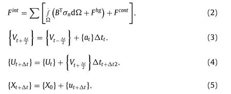
where {at} is the acceleration; {Fext} is the applied external and body force vector; {Fint} is the internal force vector;Fhgis the hourglass resistance force;Fcontis the contact force;BTis the form identical to the linear discrete strain–displacement matrix;Ωis the solid volume;σnis the internal stress; {vt} is the velocity at timet; {ut} is the displacement at timet; {x0} is the initial geometry;{xt} is the updated geometry at timet; and Δttis the difference in time of at timetcompared to the initial/selected condition.
Based at the 2019 FSAE rules, the attenuator cannot be a part of the bodywork shape; however, the alternative is to be mounted securely and immediately into the front bulkhead so that once a collision occurs, the tool needs to no longer penetrate the front bulkhead.
The impact attenuator includes three parts designed to use the thin-walled concept. The first is used cans, then rigid plates, and finally anti-intrusion plates. The used cans are set up in two levels. The early-stage includes six cans, and the higher step includes five cans. The used cans have a diameter of 72.4 mm with a thickness of two mm and a peak of 113 mm. A rigid plate has a 250 ×250 mm length with a thickness of 2 mm, which features a holder for used cans on the pinnacle stage. The closing is the anti-intrusion plate, which has a length of 325.4 ×305.4 mm. The general peak of the effect attenuator is 232 mm, as shown in Fig. 1 .
The applied material on the used cans is aluminum alloy 3004.The mechanical properties of these materials are shown in Table 1 .In the finite element calculation, it is idealized as piecewise linear plasticity with failure. This material is assumed to be a deformable component. The correlation of the strain with increasing stress is presented in Fig. 2 .

Table 1 Mechanical properties of waste food cans [30] .
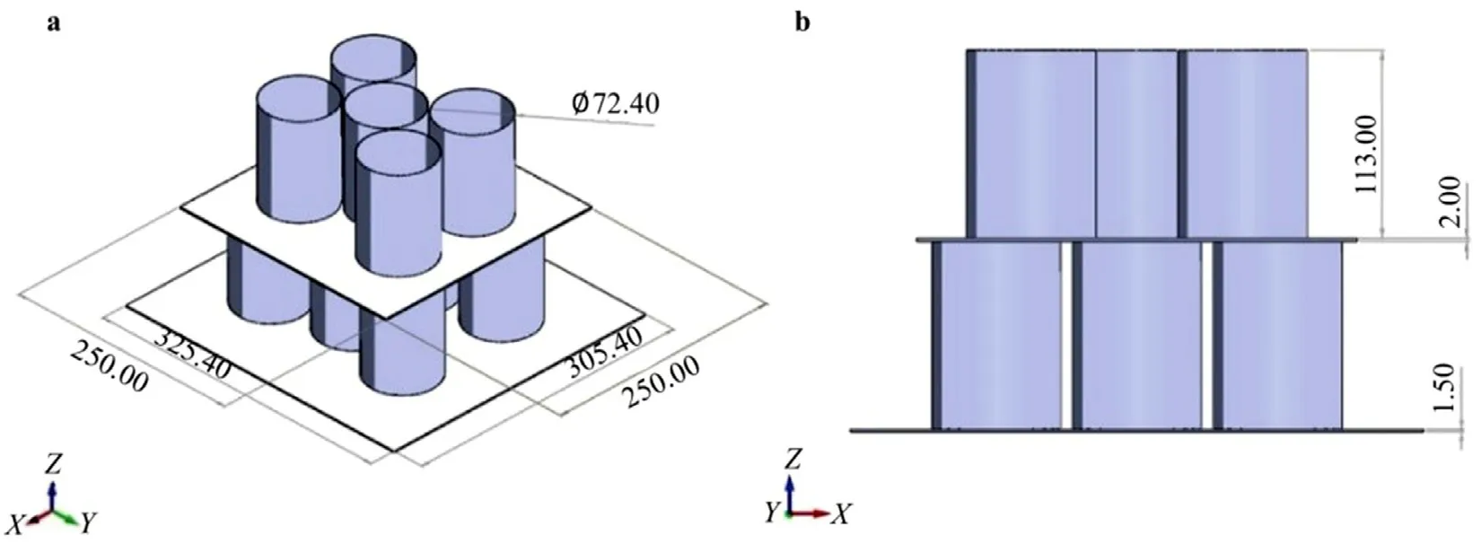
Fig. 1. Geometric model of the impact attenuator (a) isometric view; (b) left side view.
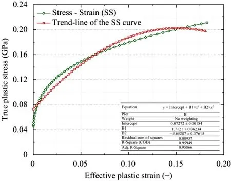
Fig. 2. Correlation of the stress–strain for the deformable component.
On the other hand, Table 2 presents the mechanical properties used in rigid parts, the first is the rigid wall as a hammer, the rigid plate, and the last is the anti-intrusion plate as a buffer.

Table 2 Mechanical properties of rigid parts [31] .
Documentation of an impact attenuator ready for compression testing using a universal testing machine (UTM) apparatus is presented in Fig. 3 . In this experimental test, the Impact Attenuator was made with the first step, namely the front bulkhead. The front bulkhead was made of steel pipe, which was cut and then welded.After that, construction was continued by cutting the basic aluminum plate with a thickness of 4 mm as the Anti-Intrusion Plate,the second aluminum plate with a thickness of 2 mm was for separating the upper and lower stack cans, and the third was an aluminum plate with a thickness of 2 mm. Then, the cans were arranged with five cans at the top and six cans at the bottom. The cans were glued so that they did not slide when pressed. Finally,the press test was carried out using a UTM tool.
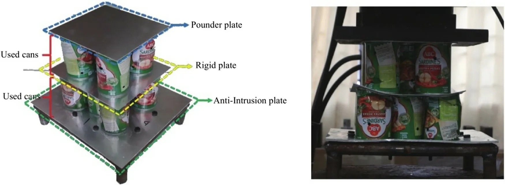
Fig. 3. Impact attenuator for the experimental tests.
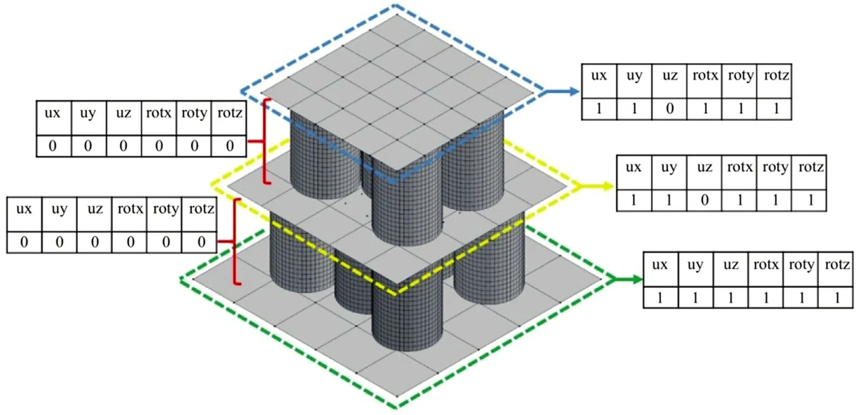
Fig. 4. Impact attenuator boundary condition.
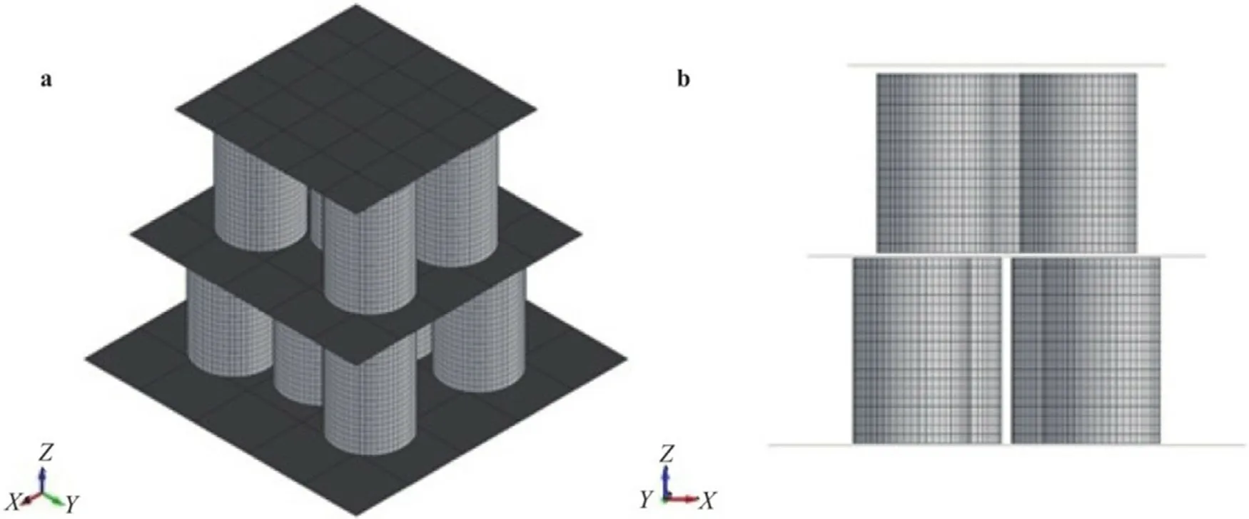
Fig. 5. Finite model of the impact attenuator (a) isometric view; (b) left side view.
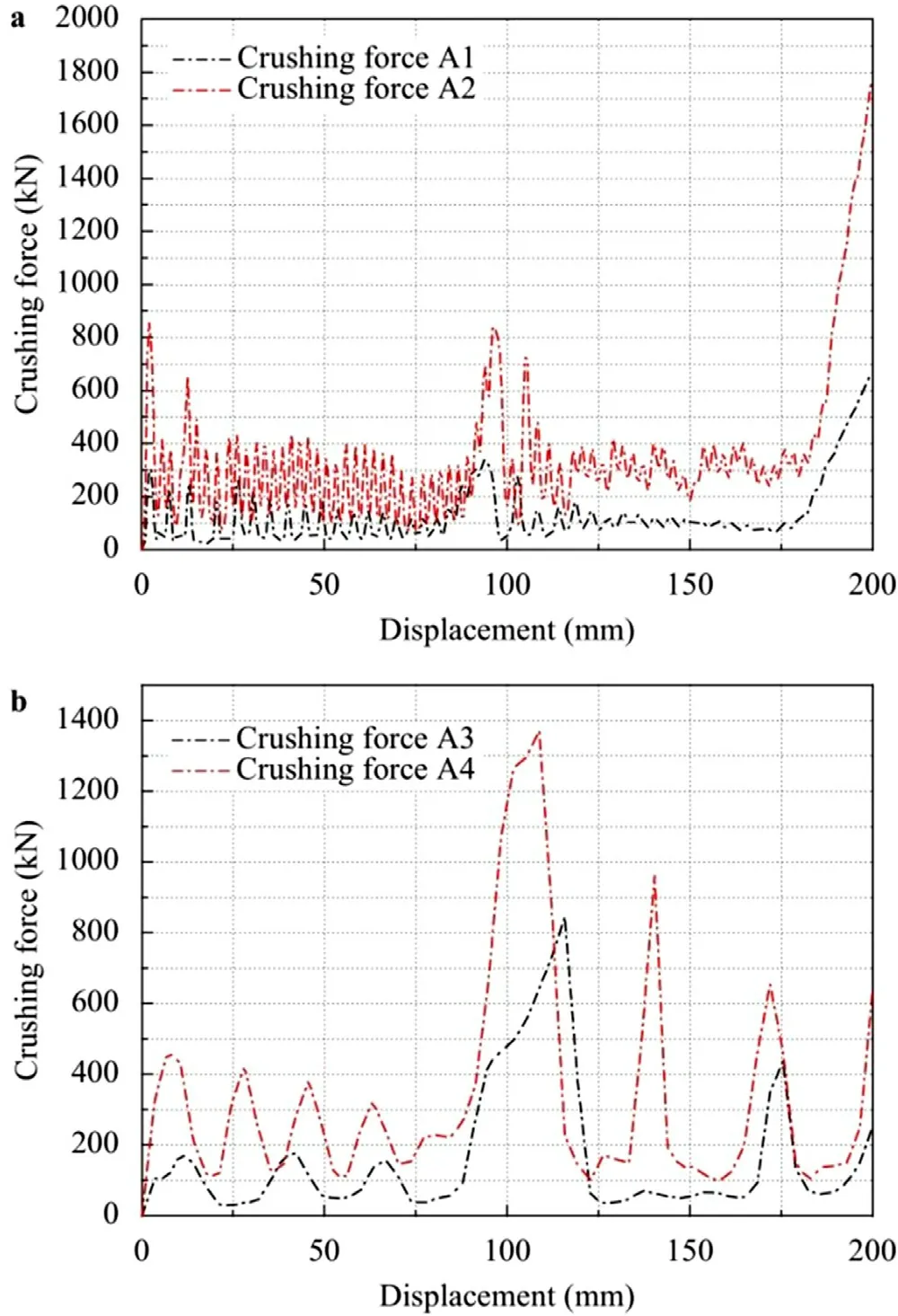
Fig. 6. (a) Crushing force A1 and A2; and (b) Crushing force A3 and A4.
The set up in the compression test was applied and adjusted to the simulation test. For the first, the impact attenuator was assumed to be a shell element type consisting of a can and a rigid plate. For the boundary condition ( Fig. 4 ), the pounder plate and the separation plate between the top and bottom cans array were fully motion-restricted (ALL DOF) unless the displacement in z (vertical) direction was specified as −200 mm. The anti-intrusion plate components were considered as non-translating and fully rotating (ALL DOF).
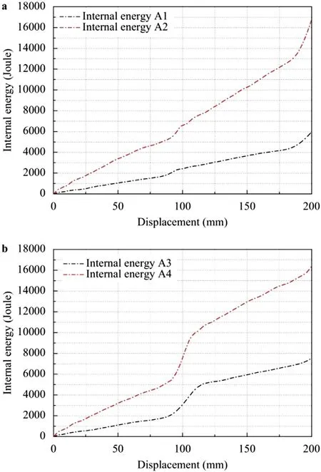
Fig. 7. (a) Internal Energy A1 and A2; and (b) Internal Energy A3 and A4.
For the used cans ( Fig. 5 ), all quadrilateral factors are modelled with a length of 5 mm. Determining the form of fabric for meal cans makes use of piecewise linear plasticity and all inflexible elements utilizing the type of severe material. This fabric choice was so that, after the collision occurs, the can will alternate in shape.The hard partitions will push the can under with a compressive pressure transmitted from the can at the top. In the input material properties for the used cans, the effective plastic strain curve shown in Fig. 2 is inputted into the define curve feature by loading the.csv data. The curve can be used as the material type featuring piecewise linear plasticity.
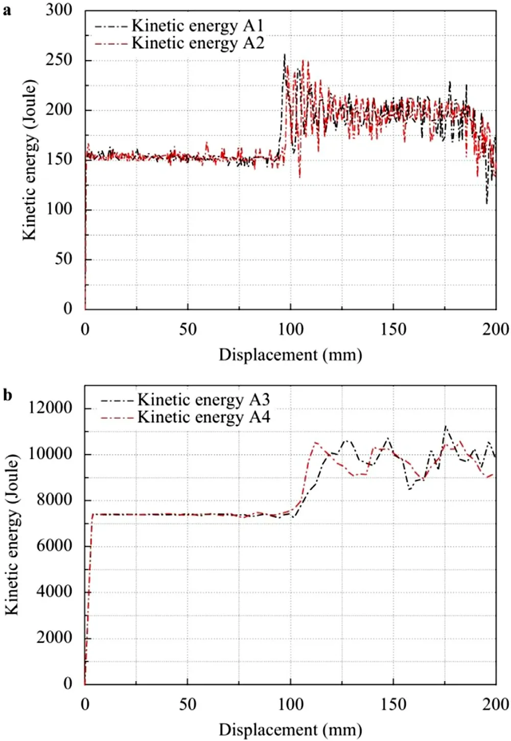
Fig. 8. (a) Kinetic energy A1 and A2; and (b) Kinetic energy A3 and A4.
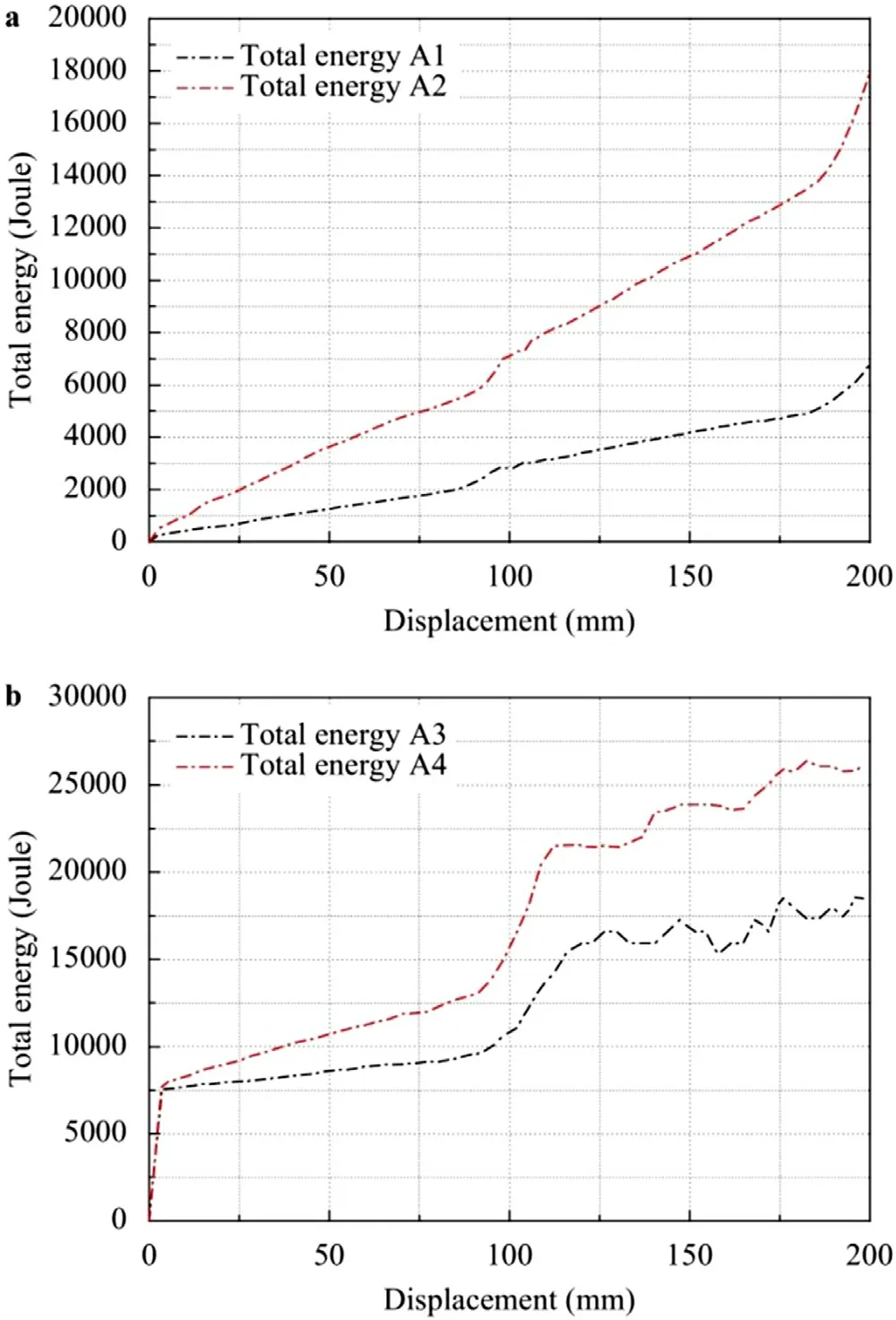
Fig. 9. (a) Total energy A1 and A2; and (b) Total energy A3 and A4.
To adjust the simulation test so that it has the same conditions as the quasi-static test, a prescribed motion rigid feature was used by defining a displacement curve, where this curve will be applied to the colliding part. This displacement curve was adjusted so that they-axis andx-axis were equal to 200 to obtain a speed of 1 mm/ms, while, for a speed of 7 mm/ms, they-axis was set at 28.5. The termination time used also adjusted to the speed applied.In the numerical modelling of the impact attenuator, contacts were used, mainly automatic node to surface and automatic single surface. Automatic node to surface contact was used to contact the rigid plate and among cans with a rigid plate and anti-intrusion plate as support.
Based on the preceding collision analysis, this kind of contact is appropriate for contacts concerning inflexible objects. The type of automatic single surface contacts was used on the wall of the can itself. This contact kind is suitable for crashworthiness applications.Based on the body interaction, the contact among the plate and the attenuator was defined as a friction phenomenon with the values of static and dynamic friction coefficients at 0.4 and 0.3, consecutively. In this research, we used two different methods to compare the final results. The first was a quasi-static test with a velocity of 1 mm/ms, and the second one had velocity according to the rules,namely 7 mm/ms. We also varied the thickness of the used cans,with the first thickness being 0.5 mm (designated as A1 and A3)and the second being 1 mm (designated as A2 and A4). Table 3 presents the variations to simulate the various conditions.

Table 3 Impact attenuator variations.
The first result is the crushing force curve as shown in Fig. 6 .The crushing force curve was derived from the total amount of force received by the can. Based on the presented results in this curve, the crushing forces A1 and A2 had velocities of 1 mm/ms.The force that works at the beginning experiences a fluctuating force value so that the curve goes up and down. With deformation around 175 mm, the curve tends to go up with a maximum force value of 1792.75 kN for A1 and 693.228 kN for A2.
For the crushing forces A3 and A4, the curve has a similar trend where, initially, the force received was fluctuating, and, when the displacement reached about 100 mm, the force value tended to increase. The force value tended to decrease but still appeared to fluctuate. In both graphs, the curve appears to have increased in the displacement area of about 100 mm. This is due to the holding force on a plate that separates the two levels of the cans so that the force’s value increases so that the bottom can begin to deform.
The internal energy ( Fig. 7 ) that occurred in A1 and A2 appears to have a similar curve trend. The same is true for the curves for A3 and A4. The A2 and A4 curves, which were cans with a thickness variation of 1 mm, had higher values of 16782.6 J for A2 and 16380.3 J for A4. From this, it can be seen that, with the same thickness variation, the results were almost the same even though the velocity of deviation was different. A1 and A3 were variations with a thickness of 0.5 mm. The results above show that the two curves were under the curve with a thickness variation of 1 mm.For A1, the internal energy reached a value of 5974.88 J, and for A3, it obtained a value of 7529.11 J.
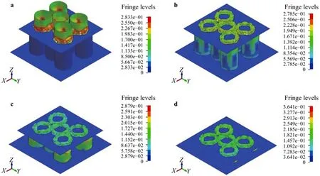
Fig. 10. Progressive contours of the von-Mises stress: (a) t = 50 ms; (b) t = 100 ms; (c) t = 150 ms; and (d) t = 200 ms.
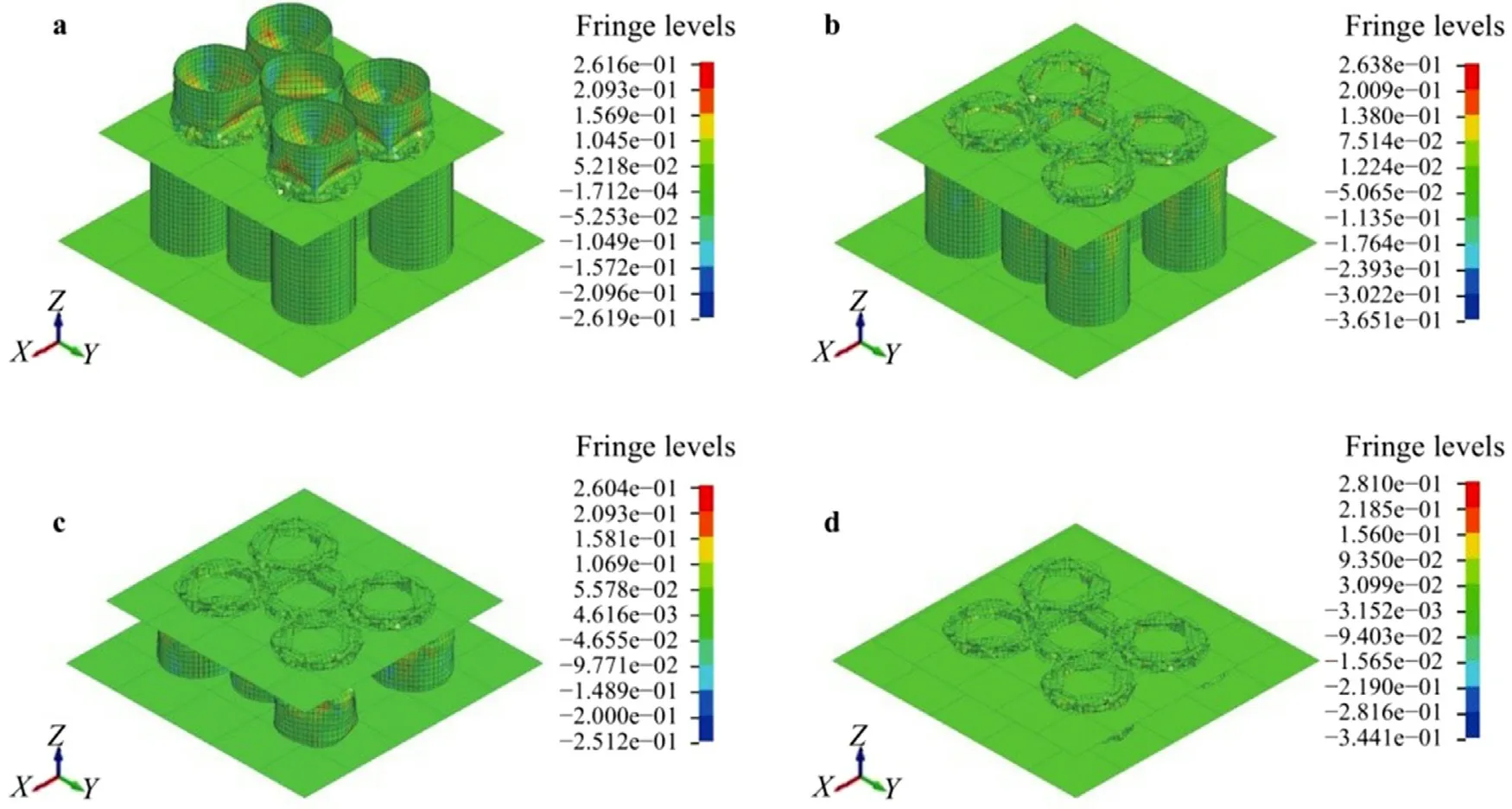
Fig. 11. Progressive contours of the z-stress: (a) t = 50 ms; (b) t = 100 ms; (c) t = 150 ms; and (d) t = 200 ms.
For kinetic energy ( Fig. 8 ), the curves from the compression test with a velocity of 1 mm/ms are for A1 and A2, and the impact test curves with a velocity of 7 mm/ms are for A3 and A4. It can be seen from the figure that the value of the kinetic energy with a velocity of 7 mm/ms had a stronger value with a large difference when compared to the kinetic energy curve with a speed of 1 mm/ms. This happens because kinetic energy is affected by the rate and, the higher the collision velocity, the greater the kinetic energy. It can be seen from the two graphs that they have almost similar curve trends.
The total energy ( Fig. 9 ) is the total amount of energy generated at the impact attenuator collision. From this curve, it can be seen that the highest total energy value was the total energy A4—namely the impact attenuator with a thickness of 1 mm and a velocity of 7 mm/ms with a value reaching 26833.4 J.
In addition to displaying the values of the energy and crushing force curves, the results also show the deformation display of the impact attenuator. The values that will be displayed in this research are the von-Misses stress, z-stress, z-displacement, and plastic strain.
Stress behavior can only be seen in certain circumstances. The red fringe levels in Fig. 10 show the maximum stress values in GPa.Therefore, in both display contours, the red color at the edge level represents the most vulnerable part of the simulated outline, while the blue color represents the most durable part. In contrast to the von-Mises stress, the stress on the z-axis has a negative sign on stress value, which indicates that the direction of stress is opposite to the direction of the axis. The red contour represents the maximum stress value along the axis and vice versa in blue, as shown in Fig. 11 .
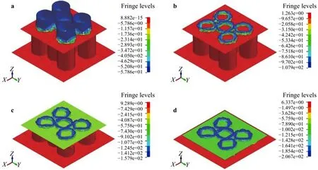
Fig. 12. Progressive contours of the z-displacement: (a) t = 50 ms; (b) t = 100 ms; (c) t = 150 ms; and (d) t = 200 ms.
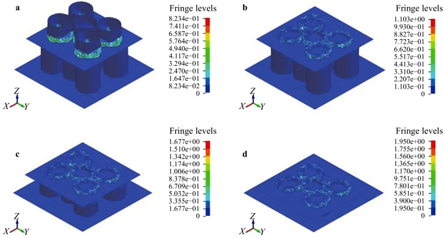
Fig. 13. Progressive contours of the plastic strain: (a) t = 50 ms; (b) t = 100 ms; (c) t = 150 ms; and (d) t = 200 ms.
The results of the structural displacement in Fig. 12 show the displacement result on the z-axis. A positive sign on the displacement value indicates that the element is moving in the direction of the axis and vice versa for the negative sign. The maximum values are shown in red for the fringe levels and blue for the minimum values.
Based on the contour of the effective plastic strain, we can observe that the impact attenuator did not experience heavy strain because almost all impact attenuators are blue, indicating that the element experienced a minimum strain. As shown in Fig. 13 , the maximum strain in the fringe scale is 0.8234 at the 50 ms step,and the maximum strain is 1.103 at 100 ms with the can at the top already deforming all over the surface. At the time of 150 ms,the maximum strain increased compared to the time of 100 ms,which was 1.677. At about 150 ms, the arrangement of the lower cans appeared as deformed.
From the internal energy curve, the highest energy value is found on the A2 curve with a value of 16782.6 J. Based on the terms and conditions that apply to the 2019 FSAE rules, the energy must be absorbed as at least 7350 J. Based on the above statement, we concluded that the A2 impact attenuator met the requirements of the 2019 FSAE regulations. The A4 impact attenuator also completed the requirements, while A1 and A3 did not meet the requirements because the value did not reach 7350 J. From this study, the collector’s velocity did not have a significant influence on the internal energy because the same thickness variation resulted in an internal energy value with a low difference and a similar curve trend.
From the results of the deformation, when viewed in the zstress section, the deformation of the impact attenuator at each step tended to increase. For the displacement that occurred on thez-axis, because the load moves against thez-axis, the displacement results displayed a high value. As for the strain, part of the impact attenuator experienced heavy strain at the end of the collision.This statement can be concluded based on contours where almost all the elements are blue, which indicates that the deformable element was flattened by the intrusion plate (a rigid component in the structure).
The impact attenuator in this study produced two variations that have values that exceeded the requirements of the FSAE rules where the passed variation had a can thickness of 1 mm. For impact attenuators with used cans, when compared to other materials that tend to be expensive and difficult to make, this canned food waste can be an alternative material to reduce costs. The availability of goods is relatively easy to obtain, so it can be said that this material is cheap because it can take advantage of used cans in relatively good condition. It is also possible that this research can contribute to protecting the environment by recycling the waste can into fundamental material in manufacturing the impact attenuator.
Declaration of Competing Interest
The authors declare that they have no known competing financial interests or personal relationships that could have appeared to influence the work reported in this paper.
杂志排行
Theoretical & Applied Mechanics Letters的其它文章
- Bifurcation mechanism of interfacial electrohydrodynamic gravity-capillary waves near the minimum phase speed under a horizontal electric field
- Research on refined reconstruction method of airfoil pressure based on compressed sensing
- Analytical solutions for sediment concentration in waves based on linear diffusivity
- Complexity analysis of the Portevin-Le Chatelier in an Al alloy at different temperatures
- Derivation of FFT numerical bounds of the effective properties of composites and polycristals
- A model for universal spatial variations of temperature fluctuations in turbulent Rayleigh-Bénard convection
