Numerical investigation on motion of an ellipsoidal particle inside confined microcavity flow
2021-07-29TinrouMioZuoliXio
Tinrou Mio ,Zuoli Xio ,b,c,*
a State Key Laboratory for Turbulence and Complex Systems, College of Engineering, Peking University, Beijing 100871, China
b HEDPS and Center for Applied Physics and Technology, College of Engineering, Peking University, Beijing 100871, China
c Beijing Innovation Center for Engineering Science and Advanced Technology, Peking University, Beijing 100871, China
Keywords: Ellipsoidal particle Microcavity Particle-flow interaction Lattice Boltamann method
ABSTRACT The behaviors of a neutrally buoyant ellipsoidal particle in vortical flow confined by a microcavity are numerically studied using the Lattice-Boltzmann method.For specific initial position,an isolated ellipsoid may develop a stable limit cycle orbit inside microcavity due to the interaction between particle and the carrier flow.It is observed that ellipsoidal particles of different shapes exhibit two different stable rotational modes depending on the initial orientation and lateral position.A prolate spheroid tends to enter a tumbling mode whereas an oblate spheroid is apt to achieve a rolling mode.The evolution of rotational velocities along the stable orbit is also analyzed for particles of different shapes.
The phenomena of inertial particle-flow interactions are fre-quently encountered in various biological and industrial applica-tions such as the flow of red blood cells in blood vessels and the flow of pollutant particles in sewage.Vortical flow with iner-tial particle entrainment is widely used in microfluidics platforms nowadays [1-3] .Understanding how inertial particles respond to the background flow in confined geometry can be of particular im-portance in designing engineered particle for targeted drug deliv-eries and high-throughput particle separation or focusing devices.
An important dimensionless number for particle-laden flows is the Stokes number (St),which is defined as the ratio of the re-laxation time of inertial particle to the characteristic time of the carrier flow.ForSt≪1,motion of a particlel almost follows the streamline,and the particle can be treated as an inertialess point.ForSt>1,the inertial force becomes dominant and the inertial effect leads to a deviation of the particle trajectory from the fluid streamline.Segré and Silberberg [4] are among the first who study the inertial effect on particle positioning inside a pipe.The results indicate that an inertial particle tends to focus at approximately 0.6r (where r is the radius of the pipe) from the centerline due to the inertial lift forces acting on the particle.Research focus is mainly placed on explanation and utilization of the inertial migra-tion phenomenon of particles.Recently,inertial microfluidics has attracted significant attention,and readers are referred to the arti-cles by Di Carlo [5],Razavi Bazaz et al.[6],and Chung [7] .
For channel flow,secondary flow is usually induced when the channel has localized structures or the curvature of the surface varies,and the resultant inertial effect become more sophisticated.Recently,the model of a straight microchannel with microcavities receives great attentions of researchers,which employs the inter-action between inertial particles and microvortex formed inside the cavity.The microchannel has been used in microfluidic devices for particle/cell manipulation and separation with high through-put [8-10] .It can also be treated as the model for blood flow in aneurysms or oil transport through fractured geological media.Haddadi and Di Carlo [11] investigate the effects of cavity aspect ratio,Reynold number and particle size on topology of the limit cycle orbit,and discuss the dynamics for particle entrapment pro-cess in details.Jiang et al.[12] introduce three entrapping phases and four particle-trapping modes,and study the orbiting and ro-tating motions of particles.
Most of the previous researches focus dominantly on spheri-cal particles.In nature and industry,however,particles are mostly non-spherical.According to the research works on non-spherical particles in flow of simple geometry [13-15],the motion of non-spherical particle is more complicated and experiences several ro-tational modes.This letter is intended to study the orbiting and rotating motions of an ellipsoid particle driven by vortical flow in-side a confined microcavity based on numerical simulation.The purpose is to study the effects of particle shape and initial position on the motion mode and shed light on the underlying physical mechanism.
Various numerical methods have been employed to study the motion of particles in fluid flows,among which the LatticeBoltzmann method (LBM) [16-18],as a mesoscopic method raised in the 1980s,becomes more and more popular in simulation of twophase flows.In this letter,the LBM with a single-relaxation time collision model (LBM-BGK) [19] is used to solve the incompressible fluid flow.The corresponding discrete control equation takes the form
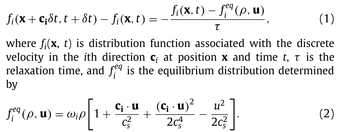
For the present three-dimensional (3D) simulation,nineteen discrete velocities model (D3Q19) is used,and the correspondingcican be readily obtained based on the direction vector (fori=0,1,...,18) and the lattice speed defined asc=Δx/Δt.Here,the sound speedcsis defined bycs=c/■3,and the lattice weightωiis prescribed as

The macroscopic density,momentum and kinematic viscosity can be obtained by

In order to describe translational and rotational motions of ellipsoidal particles,two frames of reference are employed,i.e.,the space-fixed coordinate system (X,Y,Z) and the bodyfixed coordinate system (X,Y,Z).The ellipsoidal particle is described by

wherea,bandcrepresent lengths of the three principal semiaxes,respectively.
The orientation of the body-fixed coordinates can be obtained through transformation with Euler angles (φ,θ,φ) from space-fixed coordinate system (X,Y,Z) as can be seen in Fig.1.The translation and rotation of the ellipsoid are controlled by Newton’s equation and Euler equation,respectively.Quaternion parameters are used to solve the corresponding equations [20].The force acting on the particle surface is calculated by using moment exchange method[21,22].
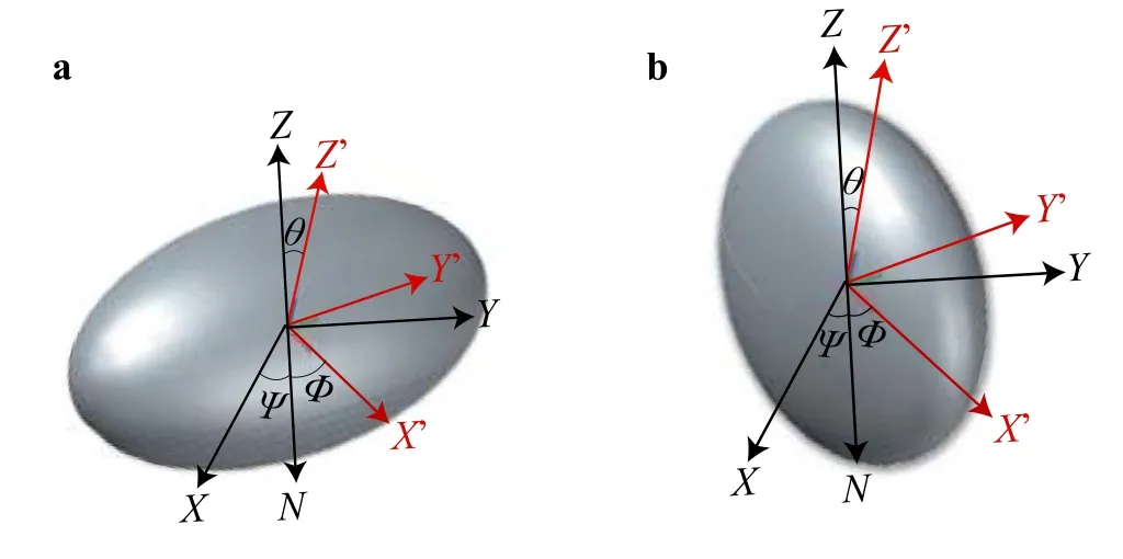
Fig.1. Schematic of the transformation between (X,Y,Z) and (X, Y, Z) coordinate systems with Euler angles (φ, θ, φ) for a prolate ellipsoid,and b oblate ellipsoid."ON" is the intersection of the (X,Y) and (X, Y) coordinate planes.
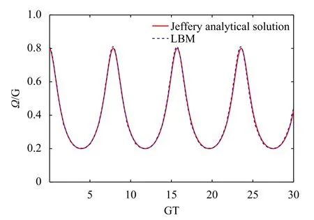
Fig.2. Validation of the simulation code in simulation of Jeffery orbits:comparison between the present LBM simulation and Jeffery’s analytical solution.
The problem of Jeffery orbits [23] is firstly simulated to validate the present LBM code.Jeffery [23] investigates the rotation behaviours of an ellipsoid suspended in Couette flow at Stokes regime analytically.If theX-axis of an ellipsoid is initially parallel to vorticity of the flow field,Jeffery’s analytical solution for the rotational angular velocity (Ω) follows

Here,Gis the shear rate of Couette flow.As seen in Fig.2,the variation ofΩwith timeTcalculated in the present LBM simulation is identical to the Jeffery’s solution,indicating the reliability and fidelity of the code.
The model of a channel with microcavity,which is proposed by Haddadi and Di Carlo [11] is shown in Fig.3.A confined rectangular microcavity is connected to a straight microchannel.The flow is driven by a constant flow rateQfrom the inlet.The lengthLch,widthWchand heightHchof the channel is 1560 μm,360 μm and 80 μm,respectively.The lengthLcaand heightHcaof the cavity is 960 μm and 320 μm,respectively,with an aspect ratio of 3.The channel Reynolds number is defined asReC=〈u〉hd/ν,wherehd=2A/Pis the hydraulic diameter determined by the cross-sectional areaAand perimeterPof the channel,〈u〉 is the mean velocity andνis the kinematic viscosity of fluid.In this work,Recis set to 120.The isolated particle is stilled inside the microcavity initially and released after the flow reaches a stable state.Two kinds of ellipsoids are studied in this work,i.e.,the prolate and oblate particles.The particle sizes are 2a=b=2c=16 μm for prolate particle anda=2b=c=12.7 μm for oblate particle.The density of particles is the same as that of the fluid.
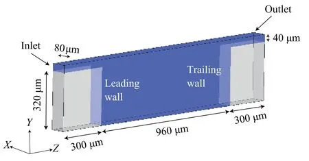
Fig.3. Geometrical model and computational domain.

Fig.4. Streamlines of fluid flow in the symmetry plane.
When the fluid suddenly expands from the channel to cavity,the velocity decreases,thus forming an adverse pressure gradient,which results in the boundary layer separation and leads to the formation of separated vortex.The vortex topology depends onReCand the cavity aspect ratio [11].ForRec=120 in the present study,a vortex of the cavity size is formed (see Fig.4).Similar to the spherical particles [11],due to the interaction between the particle and vortex,ellipsoidal particle finally tends to orbit on a stable closed trajectory inside the microcavity regardless of its initial position and orientation as long as it can be captured by the microcavity(see Fig.5 for prolate particle).The results imply that the ellipsoidal particle will spiral towards a limit cycle orbit in mid-plane of theX-axis,i.e.,the symmetry plane (see panels (a),(b) and (d)),and keeps moving along this orbit (see panel (c)) without deviation.The formation of a limit cycle orbit for finite-size particle can be qualitatively explained as the competition among the inward inertial lift effect,the outward centrifugal effect,and the Magnus effect.The particle finally reaches the orbit where these effects balance each other out [11,12].Note that similar phenomena can be observed for oblate particle (not shown here).It should be stressed that for an ellipsoidal particle,the final stable orbit may not be the same because it may experience different rotational modes,which shall be discussed in what follows.
According to the simulation results,there exist different stable rotational modes for ellipsoids of different shapes.In the present system of coordinates,rolling mode refers to the motion pattern of a ellipsoid rotating around theYaxis,while tumbling mode occurs when it rotates around theXorZaxis.Prolate particle tends to reach a stable rotational mode of tumbling,and can keep rolling only if it is initially released in the symmetry plane and its long axis (Y-axis) is along theX-axis (See Fig.6a).Otherwise,the prolate particle will change its rotation pattern gradually to tumbling mode (see Fig.6b and 6c).On the contrary,oblate particle shows a trend to achieve a rolling mode as long as its minor axis (Y-axis) slightly deviates from theY-Zplane (i.e.,the direction perpendicular to the main vortical direction),or its initial position deviates from the symmetry plane (see Fig.6d-f).In fact,Ellipsoid can reach a limit cycle orbit with both stable rotational mode and unstable rotational mode.Displayed in Fig.7 are the limit cycle orbits for an oblate particle with different rotational mode.It is clearly seen that there might exists obvious difference in the final trajectory for an ellipsoid due to different rotational mode it experiences.
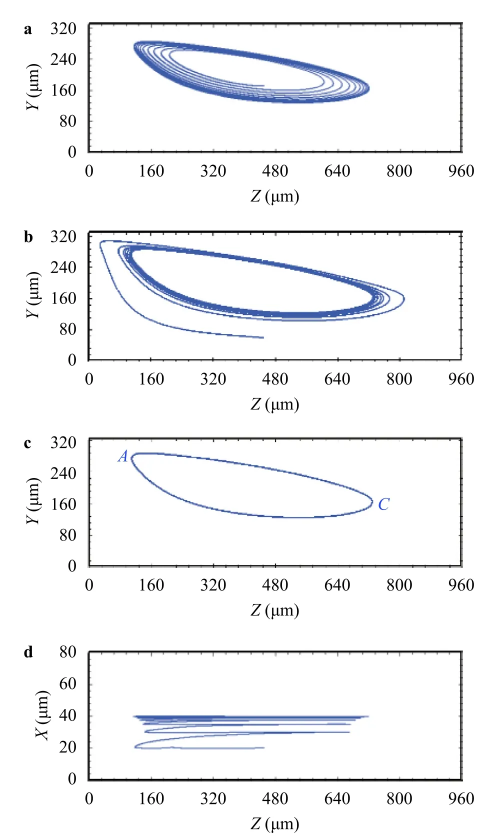
Fig.5. a Trajectory of prolate particle spiralling outward to approach the limit cycle,b trajectory of prolate particle spiralling inward to approach the limit cycle,c the limit cycle orbit,and d the trajectory projected on the X-Z plane for prolate particle.
The variation of rotational angular velocity for the two kinds of ellipsoidal particles are also examined when they move on their limit cycles.When a particle moves along its stable obit,it only hasX-component angular velocity.As shown in Fig.8,when an oblate ellipsoid moves towards the stable trajectory from adjacent planes,the angular velocities in theYandZdirections gradually approach zero (similar results are observed for prolate ellipsoid).Depicted in Fig.9a-d are temporal variations of theX-component angular velocity for prolate and oblate particles with different rotational modes.To make the description more clearly,theZ-coordinate values of moving particles are also plotted in each figure.As can be seen,for all cases the angular velocity value are quite small along the lower part of the orbit,i.e.,the part from point C to point A.Large angular acceleration appears near point A,and particles rotate fast along the upper part of the orbit,i.e.the part from point A to point C.The angular velocity variations are similar for the same rotational mode.In one period,the angular velocity has only one maximum value with rolling mode but exhibit rapid fluctuations with tumbling mode on the upper part of the orbit.The rotating velocities in theXdirection are identically positive,indicating that the ellipsoid continuously undergoes clockwise rotation,i.e.,the angular velocity points to the positiveX-axis,which is similar to previous observation for spherical particle [12].
In this letter,the dynamic behaviours of isolated ellipsoidal particle inside a confined microcavity are studied numerically using LBM at a channel Reynolds number of 120.For specific initial position,an isolated ellipsoid can be successfully entrapped by the microcavity and may develop a stable limit cycle orbit.It is further found that ellipsoidal particles with different shapes experi-ence various stable rotational modes on their limit cycle orbits.A prolate spheroid usually enters a tumbling mode while an oblate spheroid tends to announce a rolling mode.For a given spheroid,both rotational and tumbling modes can develop a limit cycle but on different orbits.The effect of Reynolds number is open for further study.
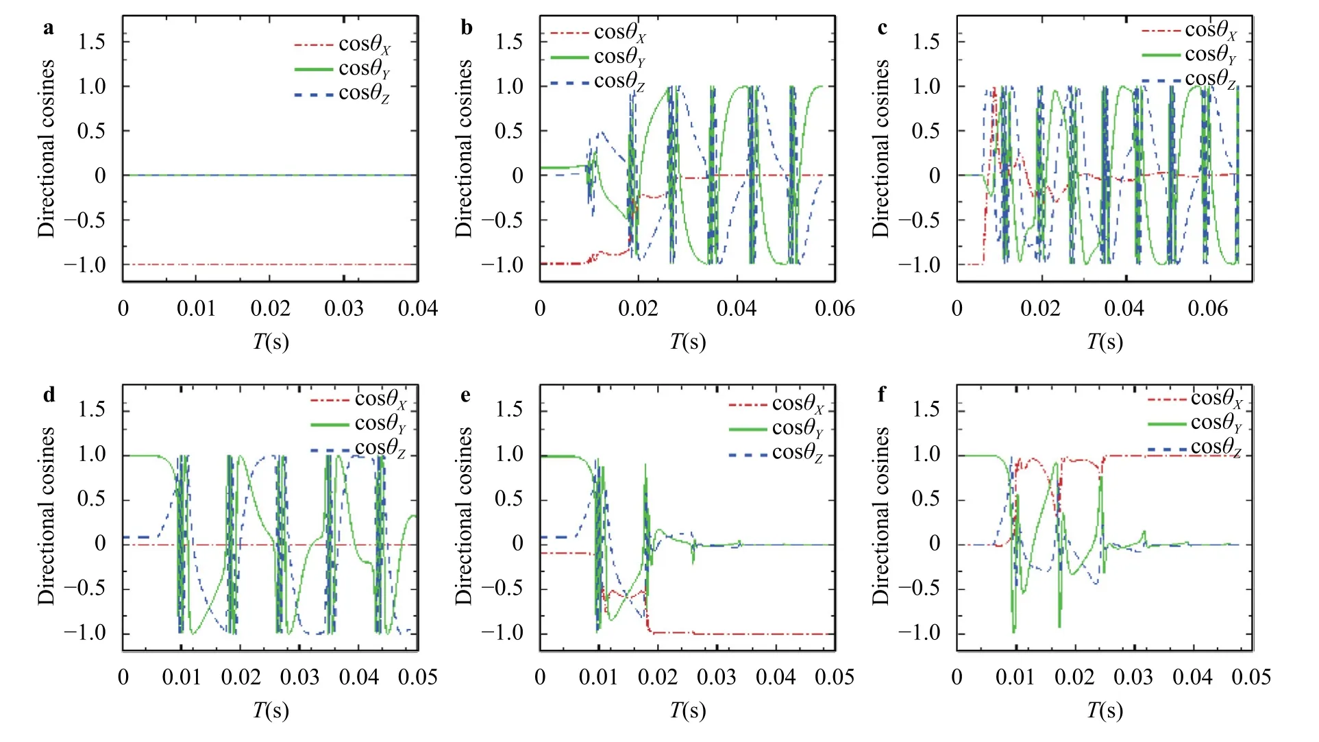
Fig.6. Temporal evolution of orientation of the prolate particle:a released in the symmetry plane with the Y -axis along the X-axis,b the Y -axis slightly deviating from the X-axis,and c released in a plane slightly deviating from the symmetry plane.Panels d,e and f are the corresponding evolutions for oblate particle.cos θX,cos θY,and cos θZ represent the cosine values of the angle between the Y -axis and the space-fixed coordinates (X,Y,Z).The particles are released at about T=6 × 10⁻³ s.
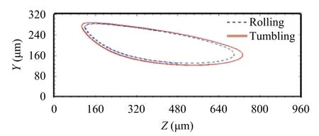
Fig.7. The limit cycle orbits for an oblate particle with different rotational modes.
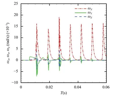
Fig.8. Temporal evolution of the angular velocities in three directions when an oblate particle moves towards the stable orbit from an adjacent plane.
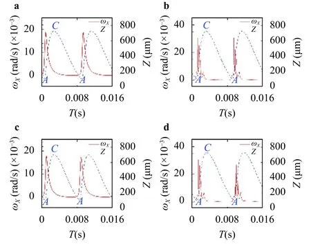
Fig.9. Comparison of the X-component angular velocity variation along the limit cycle for a prolate particle with rolling mode,b prolate particle with tumbling mode,c oblate particle with rolling mode,and d oblate particle with tumbling mode.“A”and“C”correspond to the specific locations of particles on the limit cycle as marked in Fig.5c.
DeclarationofCompetingInterest
The authors report no conflict of interest.
Acknowledgements
We are grateful to Yu Zhou for fruitful discussions on this work.Numerical simulations were conducted on the facilities (Tianhe-2) at National Supercomputer Center in Guangzhou,China.We acknowledge the financial supports provided by the National Natural Science Foundation of China (Grants 11988102 and 91852112) and the Challenge Program (Grant JCKY2016212A501).
杂志排行
Theoretical & Applied Mechanics Letters的其它文章
- Experimental investigation of sound absorption in a composite absorber
- A study of inner-outer interactions in turbulent channel flows by interactive POD
- A study on equivalence of nonlinear energy dissipation between first-order computational homogenization (FOCH) and re duce d-order homogenization (ROH) methods
- Stable heat jet approach for temperature control of Fermi-Pasta-Ulam beta chain
- Rotational dynamics of bottom-heavy rods in turbulence from experiments and numerical simulations
- Wall-resolved large-eddy simulation of turbulent channel flows with rough walls
