Wall-resolved large-eddy simulation of turbulent channel flows with rough walls
2021-07-29ShilongLiXioleiYngGuodongJinGuoweiHe
Shilong Li ,Xiolei Yng , , ,Guodong Jin ,Guowei He
a The State Key Laboratory of Nonlinear Mechanics, Institute of Mechanics, Chinese Academy of Sciences, Beijing 100190, China
b School of Engineering Sciences, University of Chinese Academy of Sciences, Beijing 10 0 049, China
Keywords: Rough wall turbulence Curvilinear immersed boundary method Wall-resolved large eddy simulation
ABSTRACT Turbulent flows over rough surfaces widely exist in nature and industry.Investigating its mechanism is of theoretical and practical significance.In this work we simulate the turbulent channel flow with rough walls using large-eddy simulation with rough elements resolved using the curvilinear immersed boundary method and compare the results obtained in this work with those in the paper by Yuan and Piomelli (J. Fluid Mech.,vol.760,pp.R1,2014),where the volume of fluid method was employed for modeling rough elements.The mean streamwise velocity profiles predicted by the two methods agree well with each other.Differences in Reynolds stresses and dispersive stresses are observed,which are attributed to the different approaches in dealing with the complex geometry of the rough surface.
Turbulent flows in nature and industry often happen with rough surfaces [1] .An abundant literature is available for turbu-lent flow in channels with rough elements of various shapes [1-3],for instance rectangular bar,cube and semi-sphere.Ignoring the specific geometry of rough elements,the simplest way for model-ing rough walls is using the logarithmic law [1,4],which can pre-dict the downward shift of the streamwise velocity profile and the increase of skin friction coefficient due to surface roughness.The logarithmic law can be expressed as follows:

where the superscript ‘+’ indicates the scaling in viscous units,i.e.y+=yuτ/νandU+=U/uτ(uτ=is the friction veloc-ity,whereτwandρare the total wall stress,which includes form stress from the roughness elements and viscous stress,and fluid density,respectively),νis the kinematic viscosity,κ≈0.4 is the Kármán constant,5<B<5.5 is a universal constant,ΔU+is the roughness function defining the roughness-dependent velocity de-fect,ksis the“equivalent”sand roughness,and zero-plane dis-placementdis the effective elevation of the boundary layer,which depends on type of roughness.Using the roughness lengthk0as the characteristic length scale,the logarithmic law for rough wall can be rewritten in the following form,

wherek0=0.033ks.The logarithmic law can predict the collective impacts of roughness elements on the outer flow,but it cannot predict the heterogeneous flow structures near the rough surface.Advanced models have been developed in the literature to account for such heterogeneous effects.For instance,Yang et al.[5] devel-oped an analytical model for the turbulent boundary layer flow over rectangular-prism roughness elements based on large-eddy simulation results.
It has been shown in the literature that the flow near the rough surface may have significant effects on related flow dynamics [1,6] .For instance,Vowinckel et al.[7] showed that the flow below the roughness crest can affect the evolution of mobile granular beds.Giometto et al.[8] demonstrated that it can affect the spatial char-acteristics of the mean flow over a realistic urban surface.Besides the mean shear in the vertical direction,wakes behind rough ele-ments dominate the flow dynamics near the rough surface.It was shown in ref.[6] that wakes behind roughness elements depend on the geometry of the roughness.And these wakes may have sig-nificant impacts on the dispersive stresses (form-induced stresses) in the lower part of the roughness sublayer,which describe the spatial heterogeneity of the time-averaged flow [9,10] .The depen-dence of the roughness function on different roughness topography was discussed by Wu et al.[11].The topographical effects of roughness on turbulence statistics in roughness sublayer were discussed by Yuan and Jouybari [12].In ref.[10],Yuan and Piomelli systematically studied the form drag,dispersive stresses,TKE budgets and WKE (wake kinetic energy) budgets in channel flows with rough walls.In [13],Wu and Piomelli examined the combined effects of roughness and adverse pressure gradient on separated turbulent boundary layers [13].
Because of the important effects of wakes behind rough elements on the turbulent flow over rough wall turbulence,it is critical to directly resolve the flow at the scale of roughness elements.Different numerical methods have been employed in the literature for rough-resolved simulations,e.g.methods based on bodyfitted grids [14,15],lattice Boltzmann method [16] and immersed boundary (IB) method [10].Methods based on body-fitted grids and lattice Boltzmann method are often limited to relatively regular rough surfaces,such as square bars [14],gradual roughness elements [15] and hemisphere [11,16].IB methods,on the other hand,can simulate flows with arbitrarily complex boundaries [17-20] .In the IB method employed in refs.[10,21,22],the volume-offluid (VOF) approach is used to represent the complex geometry of the rough wall by specifying the velocity at the grid cell cut by the rough surface based on the volume fraction of fluid.The VOF method is relatively easy to implement.One disadvantage of the VOF method is that it is less accurate in representing the geometry of the rough surface as the location and orientation of the surface is not explicitly accounted for in the cells cut by the surface.In this work,we employ the sharp interface,curvilinear immersed boundary method (CURVIB) [23],which explicitly takes into account the geometry information of the rough surface when reconstructing the velocity at grid nodes near the boundary,to simulate turbulent flows over rough surfaces and compare the obtained results with those presented in ref.[10].Specifically,we simulate the fully developed turbulent flow with rough elements,which are generated in the same way as in ref.[10] (the case R2 in ref.[10]).
In this work the LES module of the virtual flow simulator (VFSWind) [24,25] code is employed for simulating the flow over rough wall.It has been successfully applied to different environmental and energy problems [25-29].The governing equations are the three-dimensional,unsteady,filtered continuity and Navier-Stokes equations shown as follows:

wherexi(i=1,2,3)are the Cartesian coordinates,uiis theith component of the velocity vector in Cartesian coordinates,νis the kinematic viscosity,pis the pressure,andτijrepresents the anisotropic part of the subgrid-scale stress tensor,which is modeled by the dynamic subgrid-scale model [30].The governing equations are discretized in space using a second-order accurate central differencing scheme,and integrated in time using the fractional step method [23].An algebraic multigrid acceleration along with a GMRES solver is used to solve the pressure Poisson equation.A matrix-free Newton-Krylov method is used for solving the discretized momentum equations.
The CURVIB [23] is employed in VFS-Wind to represent complex boundaries.As show in Fig.1a,the Cartesian grid nodes are classified as fluid nodes located in the fluid and solid nodes located in the solid.The fluid nodes with at least one neighbor in the solid are marked as IB nodes (e.g.pointbin Fig.1a).In CURVIB,the velocity at IB nodes are constructed in the wall normal direction using the velocity at the boundary (pointain Fig.1a) and velocity in the fluid (pointcin Fig.1a),where the velocity at pointcis interpolated from the surrounding fluid nodes.For wall-resolved largeeddy simulation,in which pointbis located in the viscous sublayer,the linear interpolation is employed.For wall-modeled largeeddy simulation,in which the viscous sublayer is not resolved by the grid,the velocity at pointbis constructed using a wall model[5,24,31,32].
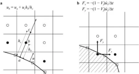
Fig.1. Different treatment of rough surfaces for a the CURVIB method,where u a,u b and u c are the velocities at point a, b and c, respectively,and h b and h c are the length of segment ab and ac and b the VOF method,where F x and F y are the x and y components of the forcing term F.
The simulation results of this work will be compared with results from Yuan and Piomelli [10] by Yuan and Piomelli,which are computed using the VOF method.Here we briefly describe the VOF method employed in ref.[10].In this method,the flow is first solved without the forcing to obtain the preliminary vel ocityThen the forcing terms applied to the grid cells c ut by the boundary (field circles shown in Fig.1b) are calculated bywhereVfis the volume fraction of fluid,andΔtis the time step.This forcing term is determined by requiring that the velocity at the cells cut by boundary is equal toVfWith this forcing term,the governing equations are solved to obtain the velocity for this time step.
We simulate the turbulent channel flow over rough wall,which has been carried out earlier by Yuan and Piomelli [10].The Reynolds number based on the channel heighthand the bulk velocityUbisRe=12207.A schematic of the rough surface employed in this work is shown in Fig.2,which is generated using the virtual sandgrain model proposed in ref.[21].In this approach,the bottom surface is partitioned into square tiles of size 2r×2rwith each tile containing a randomly rotated ellipsoid with semiaxesr,1.4rand 2rand its center located atz0=-0.5r(as shown in Fig.2).In the simulated case,the value ofris set asr/h=0.07 corresponding to the fully rough regime (the R2 case in ref.[10]),wherehis the height of the channel.It is noticed that the“equivalent”sand roughnessks=ris known a priori given by the virtual sandgrain model [21].
The size of the computational domain is 6h×h×3hinx,yandzdirection,respectively,which has been shown sufficient to accommodate the largest turbulent structures for a smooth-wall channel flow [10].The free-slip boundary condition is applied at the top boundary,while at the bottom wall with rough surface,the no-slip condition is employed.Periodic boundary conditions are imposed in the streamwise and spanwise directions (xandz,respectively).The computational domain is discretized using 1024×128×512 grid nodes in thex,yandzdirections,respectively (uniform grids in thexandzdirections),with each square tile resolved by 24 grid nodes in the horizontal directions.The grid is refined near the wall in theydirection (as shown in Fig.2),with the first off grid spacingΔy/h=3.75×10-3and 28 nodes allocated below the roughness crest.The size of time step isΔtUb/h=2×10-3.In the present case,the flow is driven by a mean pressure gradient,which is computed by maintaining a constant mass flux.The flow is first simulated for about 20 flow-throughs to achieve a fully developed state.Then the turbulence statistics are obtained by continuing the simulation for about 30.7 flow-throughs.
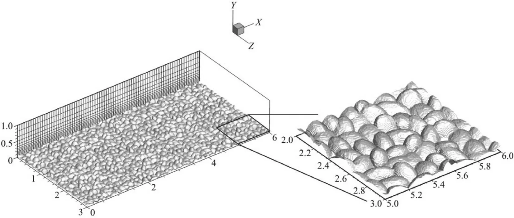
Fig.2. Schematic of the computational domain and the rough surface.On the slice,every tenth grid line is displayed.
A space-time double-averaging approach [9] is used to analyze turbulence statistics.In this approach,a flow quantityθcan be decomposed into space-time average,the spatial variation of the temporal average,~θ,and the turbulent fluctuationθ′as follows:

We present our the simulation results and compare them with Yuan and Piomelli’s [10].In this work,we fix the bulk velocity in the simulation and compute the friction velocity based on the forces exerted on the rough elements.The Reynolds number based on the channel lengths (h) and friction velocityuτisReτ=1050 for the present case,close toReτ=1000 of ref.[10],with the roughness heights in wall unit=75 and=72 respectively for our case and that in ref.[10].We first show the instantaneous flow field in Fig.3.As seen,the wake behind each rough element and the heterogeneous distribution of the streamwise velocity are well captured by the employed method.In Fig.4 we show the temporally and horizontally averaged streamwise velocity profile in wall units.It is seen that the velocity profile computed from this work agrees well with that in ref.[10] with the normalized velocity defect in the logarithmic region approximately 7.8.Differences are observed in the roughness sublayer (i.e.y <2kswith its physical meaning discussed later),where the mean streamwise velocity profile predicted in this work is slightly lower than that from ref.[10].This is probably because of the different treatments of rough elements in the two methods that the no-slip boundary condition is explicitly imposed in the CURVIB method but not in the VOF method.
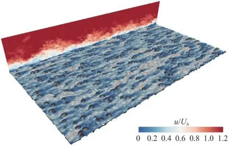
Fig.3. Contour of instantaneous streamwise velocity on the x-y plane located at x/h=0 and the x-z plane located at y/h=0.07, respectively.Where U is the instantaneous streamwise velocity.
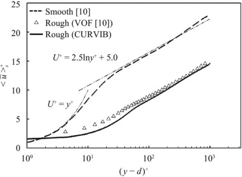
Fig.4. Comparison of the vertical profiles of the streamwise velocity computed using the CURVIB method with that computed using the VOF method [10] and that of of smooth channel.
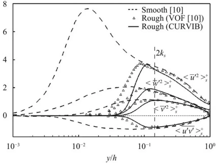
Fig.5. Comparison of the Reynolds stresses computed using the CURVIB method with those computed using the VOF metho d and thos e of smooth channel.The Reynolds stresses are normalized using
In Fig.5 we compare the Reynolds stresses normalized byu2τas a function ofy/hcomputed from this work,with those from the smooth wall case (Reτ=1000) and the same rough wall case in ref.[10].As seen,different terms of the Reynolds stresses are similar with each other in the outer layer down to the edge of roughness sublayer located aty≈2ksfor different cases.This indicates that the friction velocity properly scales turbulence in the outer layer even for cases of different wall roughness.When compared with the results from the smooth wall case,it is observed that the peaks of Reynolds stresses are shifted outward and siginificantly damped in the region close to the rough surface,where the viscous sublayer and the buffer layers are destructed for rough wall turbulence in the fully rough regime.Compared with Yuan and Piomelli’s results [10],the locations of peaks of the Reynolds stresses are slightly farther from the wall with the magnitudes of the Reynolds stresses damped more faster as moving from peak locations to the wall.
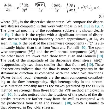
After showing the Reynolds stresses,here we examine the spatial heterogeneity of the flow field.We first show the timeaveraged streamwise velocity was not uniform on thex-zplane located at(y-d)+=10 as in Fig.6.As seen,the spatial distribution of the streamwise velocity is highly variable due to the rough surface formed by random rotated ellipsoids.These observed spatial heterogeneity results in the dispersive stresses [34].Taking the dispersive shear stress as an example,it appears in the temporally and horizontally averaged momentum equation as follows:
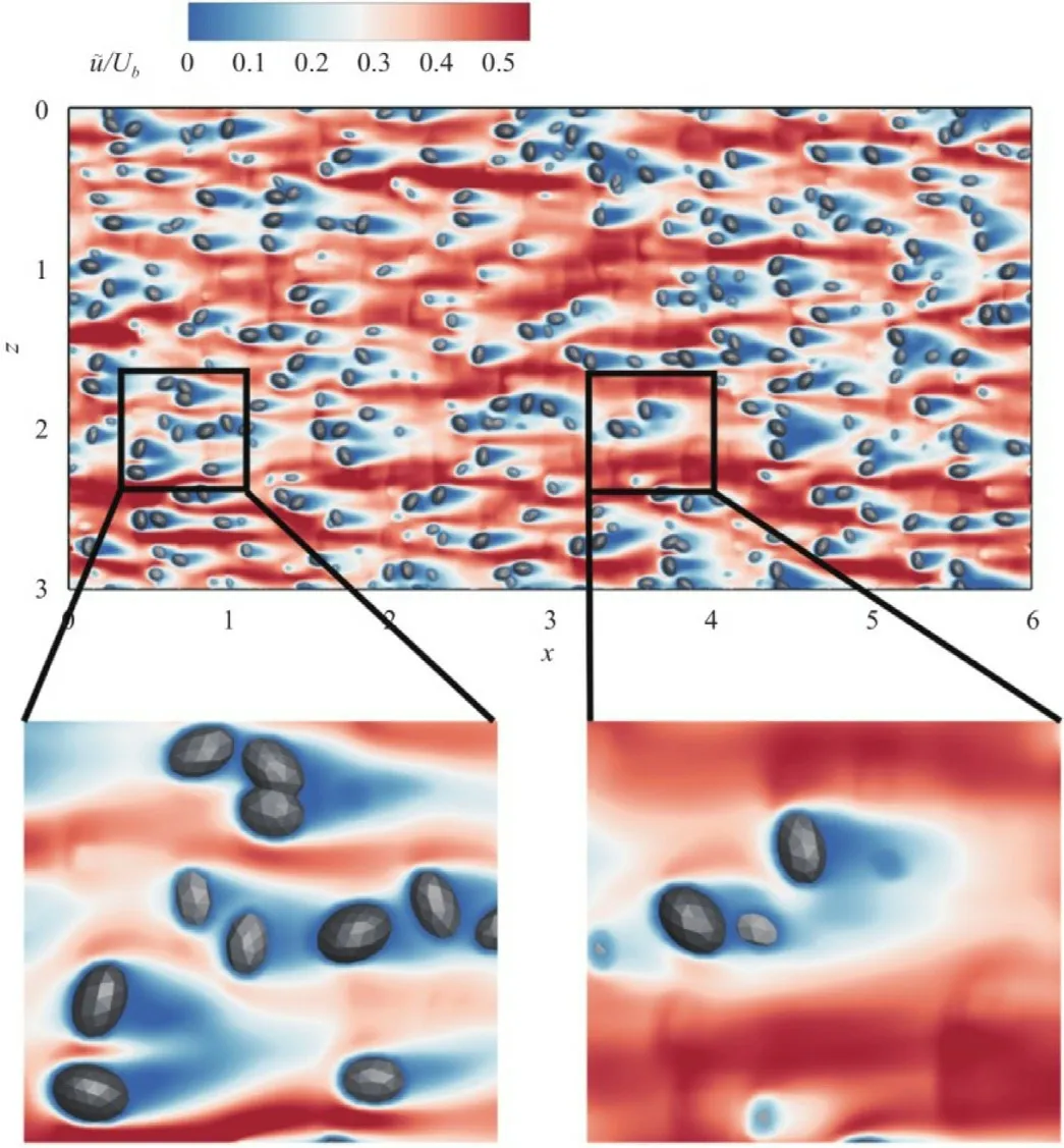
Fig.6. Contours of time-averaged streamwise velocity on the x-z plane located at(y-d)+=10 with two regions of the slice is zoomed in with one containing more rough elements cut by the slice than the other.
In this work,we carry out LES of turbulent channel flow over rough wall with the rough surface represented using the sharp interface CURVIB method.In the simulated case,the“equivalent”sand roughness is the same as that in the work by Yuan and Piomelli [10],in which the roughness elements were modeled using the VOF method.The simulation results from this work are compared with those from Yuan and Piomelli [10].For the nor-mal Reynolds stressesthe predictions from this work are similar to ref.[10] in the outer region,while they are smaller than those from Yuan and Piomelli [10] in the rough wall region.For the dispersive stress,the peak of the streamwise componentcomputed from this work is higher than that from Yuan and Piomelli [10],while the vertical and spanwise componentsand the magnitude of the dispersive shear stress are lower than those from Yuan and Piomelli [10].
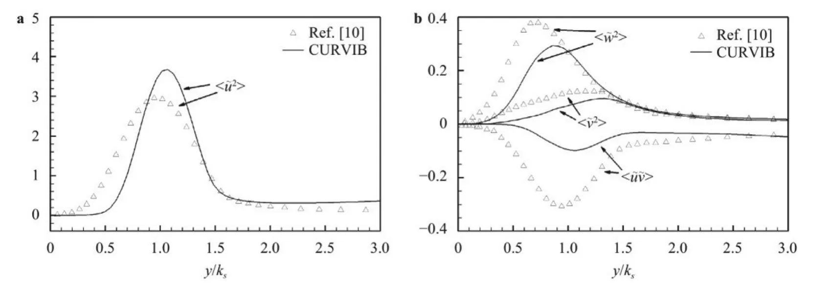
Fig.7. Comparison of the dispersive stresses computed using the CURVIB method with those computed using the VOF method [10] for a the streamwise component and b other components.The dispersive stresses are normalized using
The differences observed between the predictions of this work and those in ref.[10] can be explained by the different treatments of roughness elements.In the VOF method employed in ref.[10],the velocity at those cells cut by the boundary is specified based on the volume fraction of fluid,while in the CURVIB method [10],the velocity at the IB node is reconstructed by directly satisfying the boundary conditions at the surface of the rough element.This difference probably results in larger form drag and stronger wakes behind rough elements,causing differences in the predictions of Reynolds stresses and dispersive stresses.
DeclarationofCompetingInterest
The authors declare that they have no known competing financial interests or personal relationships that could have appeared to influence the work reported in this paper.
Acknowledgment
This work was supported by the National Natural Science Foundation of China (NSFC) Basic Science Center Program for“Multiscale Problems in Nonlinear Mechanics”(Grant No.11988102)and the NSFC Program (Grant No.11772337),the Science Challenge Program (Grant No.TZ2016001),the Strategic Priority Research Program,Chinese Academy of Sciences (CAS) (Grant No.XDB22040104),the Key Research Program of Frontier Sciences,CAS(Grant No.QYZDJ-SSW-SYS002) and the CAS Center for Excellence in Complex System Mechanics.We are grateful to Junlin Yuan for providing us their simulation data in ref.[10] and her helpful suggestions.
杂志排行
Theoretical & Applied Mechanics Letters的其它文章
- Experimental investigation of sound absorption in a composite absorber
- Physics-informed deep learning for digital materials
- Numerical investigation on motion of an ellipsoidal particle inside confined microcavity flow
- A multi-scale algorithm for dislocation creep at elevated temperatures
- Constraine d large-e ddy simulation of turbulent flow over inhomogeneous rough surfaces
- Rotational dynamics of bottom-heavy rods in turbulence from experiments and numerical simulations
