Robotic Intra-Operative Ultrasound: Virtual Environments and Parallel Systems
2021-04-13ShuangyiWangMemberIEEEJamesHousdenTianxiangBaiHongbinLiuMemberIEEEJunghwanBackDavinderSinghKawalRhodeZengGuangHouFellowIEEEandFeiYueWangFellowIEEE
Shuangyi Wang, Member, IEEE, James Housden, Tianxiang Bai, Hongbin Liu, Member, IEEE, Junghwan Back,Davinder Singh, Kawal Rhode, Zeng-Guang Hou, Fellow, IEEE, and Fei-Yue Wang, Fellow, IEEE
Abstract—Robotic intra-operative ultrasound has the potential to improve the conventional practice of diagnosis and procedure guidance that are currently performed manually. Working towards automatic or semi-automatic ultrasound, being able to define ultrasound views and the corresponding probe poses via intelligent approaches become crucial. Based on the concept of parallel system which incorporates the ingredients of artificial systems, computational experiments, and parallel execution, this paper utilized a recent developed robotic trans-esophageal ultrasound system as the study object to explore the method for developing the corresponding virtual environments and present the potential applications of such systems. The proposed virtual system includes the use of 3D slicer as the main workspace and graphic user interface (GUI), Matlab engine to provide robotic control algorithms and customized functions, and PLUS (Public software Library for UltraSound imaging research) toolkit to generate simulated ultrasound images. Detailed implementation methods were presented and the proposed features of the system were explained. Based on this virtual system, example uses and case studies were presented to demonstrate its capabilities when used together with the physical TEE robot. This includes standard view definition and customized view optimization for pre-planning and navigation, as well as robotic control algorithm evaluations to facilitate real-time automatic probe pose adjustments. To conclude, the proposed virtual system would be a powerful tool to facilitate the further developments and clinical uses of the robotic intra-operative ultrasound systems.
I. INTRODUCTION
MEDICAL ultrasound (US) is an important imaging modality which can provide real-time evaluation of patients. Compared with many other modalities, an ultrasound scan is easy to perform, substantially lower in cost, and it does not use harmful ionizing radiation. The research interest in robotizing ultrasound systems has always been a popular topic since the late 1990s within the European Union, North America, and Japan. This was because robotized ultrasound systems could potentially solve the deficiencies of the on-site manual manipulation of hand-held probes, such as difficulties of maintaining accurate probe positioning for long periods of time using human hands [1] and the requirements for experienced sonographers to be on-site [2]. Among these robots, many efforts have been made in robotizing intraoperative ultrasound systems in order to provide easier, more stabilized replacements for manually-controlled intraoperative ultrasound devices.
As one of the most widely-known examples of intraoperative ultrasound, trans-rectal ultrasound is widely employed to guide radical prostatectomies. The probe used for these examinations, known as the trans-rectal ultrasound(TRUS) probe, has been robotized with various configurations to facilitate the clinical use. Example works from Han et al.presented a 4-DOF robotic TRUS system to scan the prostate volume with rotary sweeps using a 2D TRUS probe [3], [4].The system was tested along with the da Vinci surgical robot.As the outcome, both the da Vinci tools and the blood vessels associated with neurovascular bundles were clearly visualized and the nerve-sparing radical prostatectomy procedure was successfully performed. The benefit of using the robotic system is that it can measure positions intrinsically without the need for separate tracking systems. Accurately tracking of the probe postures by the robot makes the 3D reconstruction of the prostate using the 2D TRUS probe possible.
In addition to the capability of registration and 3D reconstruction, Adebar et al. [5] proposed another robotic TRUS system which includes the capability of elastography, a modality for measuring elastic properties and stiffness characteristics of the soft tissue. With the use of the robot,automatically tracking of the existing da Vinci surgical tools was also discussed in [6]. Moreover, work presented by Schneider et al. described a partially motorized TRUS system with an integrated biopsy needle to be used during prostate biopsy procedures [7]. The combination of ultrasound imaging and needle insertion enables the registration of the needle with the ultrasound image precisely, resulting in accurate needle placements. Similarly to the prostate biopsy procedure,prostate brachytherapy requires placement of radio-activated sources under the guidance of ultrasound images. Work such as that reported by Podder et al. [8] demonstrated a complete robotic prostate brachytherapy system, which includes both the TRUS movement and needle insertion functions.
Another important contribution from Loschak et al.described an add-on 4-DOF robot which can hold and manipulate an intra-cardiac echocardiography (ICE) catheter[9], [10] remotely. Differently to the TRUS probe, the much thicker ICE catheter is a snake-like steerable device. The tip of the device can be bent bi-directionally controlled via rotational knobs on the handle. The catheter acquires ultrasound images of adjacent tissues from its distal tip and can be guided through the vasculature to access the internal structures of the heart. The remote-control capability of the robot was demonstrated, but more focus of the research series was on intelligent control and navigation. Example includes the auto-sweeping of multiple image planes for 3D reconstruction and the automatic pointing at and imaging targets via tracking and feedback control.
Following these works, we have developed the first transesophageal ultrasound robot and the accompanying semiautomatic acquisition workflow in recent years, as presented in [11], [12]. This was to robotize the trans-esophageal echocardiography (TEE), a widely used imaging modality for diagnosing heart disease and guiding cardiac surgical procedures. The work was motivated by the challenges that many cardiac procedures where TEE is utilized are usually accompanied by X-ray fluoroscopy imaging. In such scenario,the operator is required to stand for long periods of time and wear heavy radiation-protection shielding. The protection aprons are heavy and can cause orthopedic injuries to echocardiographers and cardiologists due to the weight of the protective shielding [13] and the result of holding the probe in one hand while adjusting scanning parameters with the other hand for prolonged periods of time. Moreover, the need for highly specialized skills is always a barrier for reliable and repeatable acquisition of ultrasound, especially in developing countries [2].
With all these robotic intra-operative ultrasound systems, a common challenge towards standardization and intelligence would be the pre-planning and navigation. Pre-planning would use the pre-operative data of the patients and define the target locations of the robotic end-effectors, i.e., ultrasound transducer, while the navigation would utilize the tracking data of the ultrasound transducer to facilitate the real-time control of the robots. In addition to the pre-planning and navigation, repetitive testing the control algorithms of these robots on a daily basis could also be another challenge as realistic experimental environments with both pathways and anatomical structures, e.g., customized phantom or cadaver facilities, are normally difficult to be accessed, expensive to use, or not yet available for lab tests. Considering these demands for the developments and uses of the intra-operative ultrasound robots, digital environments using computational techniques which include the modeling of the robot, realistic anatomic data of the organs and pathways, and the simulation of the ultrasound images would be a powerful tool for developing the pre-planning and navigation methods, as well as testing robot control algorithms.
As an example that has been investigated in the previous related work [12], a simplified view-planning platform was utilized to plan poses of the ultrasound transducer, i.e., distal end of the probe, based on pre-scanned volumetric data. In the study, experiments using customized phantom were performed and it has been proved that with such a virtual environment to define target poses of the transducer before and during a scan, semi-automatic ultrasound acquisition using robot is feasible with clinically acceptable positioning errors (within 1 cm). This result has indicated the use of robot with a simulation platform could potentially improve the general usability of intra-operative ultrasound and assist operators with less experience. However, the function of the view-planning platform presented in the previous work was limited in several aspects: 1) it is a Unity-based system that is relatively difficult to interface with other tools for nontechnical users; 2) the study has not yet treated the simulation system as the equally-important research object and therefore has been limited in many functions to support defining probe poses before and during a scan, e.g., does not generate simulated ultrasound image and allow customized probe control algorithms to be included.
Treating the virtual environment as an equally-important study object, the concept of digital environments can be further related to the concept of parallel systems and parallel control theory proposed by Wang [14], [15]. The basic structure of parallel systems is shown in Fig. 1. The idea of parallel control is expanding the practical problems into virtual space, then the control tasks can be realized by means of virtual-reality interaction. To be specific, parallel control is the application of artificial systems, computational experiments, parallel execution (ACP) theory [16] in control theory, where artificial systems (A) are used for modeling the physical systems, computational experiments (C) are used for analysis, evaluation and learning, and parallel executions (P)are utilized for control, management, and optimization. In the past decades, the concept of ACP has been successfully implemented in many applications when analyzing and developing cyber-physical systems [17], [18], e.g., the use of ACP in the automatic pilot system, intelligent city, and unmanned mining.
Following the work presented in [12] that has already indicated the value of the simulation platform to support semiautomatic TEE acquisition by phantom experiments, we are now motivated to focus and further develop the virtual environment for intelligent TEE view planning and treat it as equally important as the study of the robot itself. In this paper,we employ the concept of the parallel systems and adapt its generic structure to the specific application of the robotic intra-operative ultrasound. As an example, a virtual environment to represent the physical acquisition system of the robotic TEE is presented with its implementation methods introduced. Based on this proposed virtual environment,example uses of the platform were introduced to demonstrate the potential applications of the proposed parallel system and its interaction with the physical system. The main contributions of this research are as follows: 1) Expanding the basic concept of the parallel system theory by adjusting it to be suitable for more specific medical-driven applications, e.g.,intra-operative ultrasound; 2) Being the first study attempting to include both the clinical procedure simulation and the virtual robotic control into one environment for the roboticassisted intra-operative ultrasound; 3) Demonstrating the functions and example uses of the simulation environment to define and plan ultrasound standard views via different approaches and therefore support the transformative automatic acquisition workflow proposed in [12]. In the following contents, the physical system of the robotic trans-esophageal ultrasound is introduced first in Section II. The implementation methods of the virtual environment and the parallel system are presented in Section III, followed by Section IV to demonstrate the example uses and case studies of the proposed virtual system. At the end of the paper in Section V, the discussions were presented and the conclusion was made.
II. OVERVIEw OF THE ROBOTIC-ASSISTED TRANSESOPHAGEAL ULTRASOUND
TEE is normally performed with an ultrasound scanner and a specially elongated probe, known as the TEE probe. A TEE probe usually comprises a control handle with two concentric wheels, an electronic interface, a flexible shaft, and a miniaturized ultrasound transducer mounted on the distal tip.In the current clinical practice, the 2D multiplane TEE has been widely used and a set of 20 standard views, intended to facilitate and provide consistency in training, reporting,archiving, and quality assurance, were published by the American Society of Echocardiography (ASE) and the Society of Cardiovascular Anesthesiologists (SCA) for performing a comprehensive multiplane TEE examination [19]. This guideline describes the techniques of manipulating the probe to the desired locations to acquire these 20 views, known as the 2D TEE standard views or 2D TEE protocol.
The associated novel TEE robotic system developed and studied in [11] was aimed to robotize a commercial TEE probe. As shown in Fig. 2, a normal TEE probe can be attached to the add-on robot and the robot would manipulate four degrees of freedom (DOFs) that are available in manual handling of the probe, including the rotation about and translation along the long axis of the TEE probe and additional manipulators with 2-DOFs to bend the probe head.The bending functions were achieved by two rotational wheels precisely formed to mate with and drive the original wheels on the TEE probe handle. The mechanism for the rotational axis of the robot can rotate the whole probe about its long axis 360 degrees. In addition, a linear actuating mechanism and two rails attached to the base frame were developed to provide the translational movement of the probe. This robot has been tested thoroughly with its workspace, repeatability error, and kinematic accuracy reported in the previous work [11]. It has been demonstrated that the robot design is acceptable comparing with the clinical requirements of TEE acquisition.

Fig. 2. Overview of the proposed physical robotic TEE system.
Based on the abovementioned clinical procedure and physical systems, the basic requirements of the corresponding virtual environments are listed as follows: 1) representing the patient heart, esophagus, and cardiac ultrasound images; 2)simulating the motion of the probe, i.e., the ultrasound transducer within the esophagus based on the robotic kinematics; 3) interacting with the user or the customized code to control the probe.
III. IMPLEMENTATION METHODS OF THE VIRTUAL ENVIRONMENT AND THE PARALLEL SYSTEM
A. System Architecture Overview
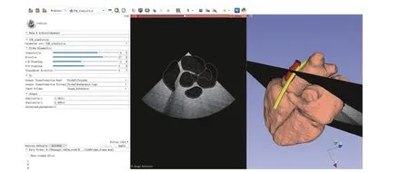
Fig. 3. GUI of the proposed virtual TEE system implemented in 3D slicer.
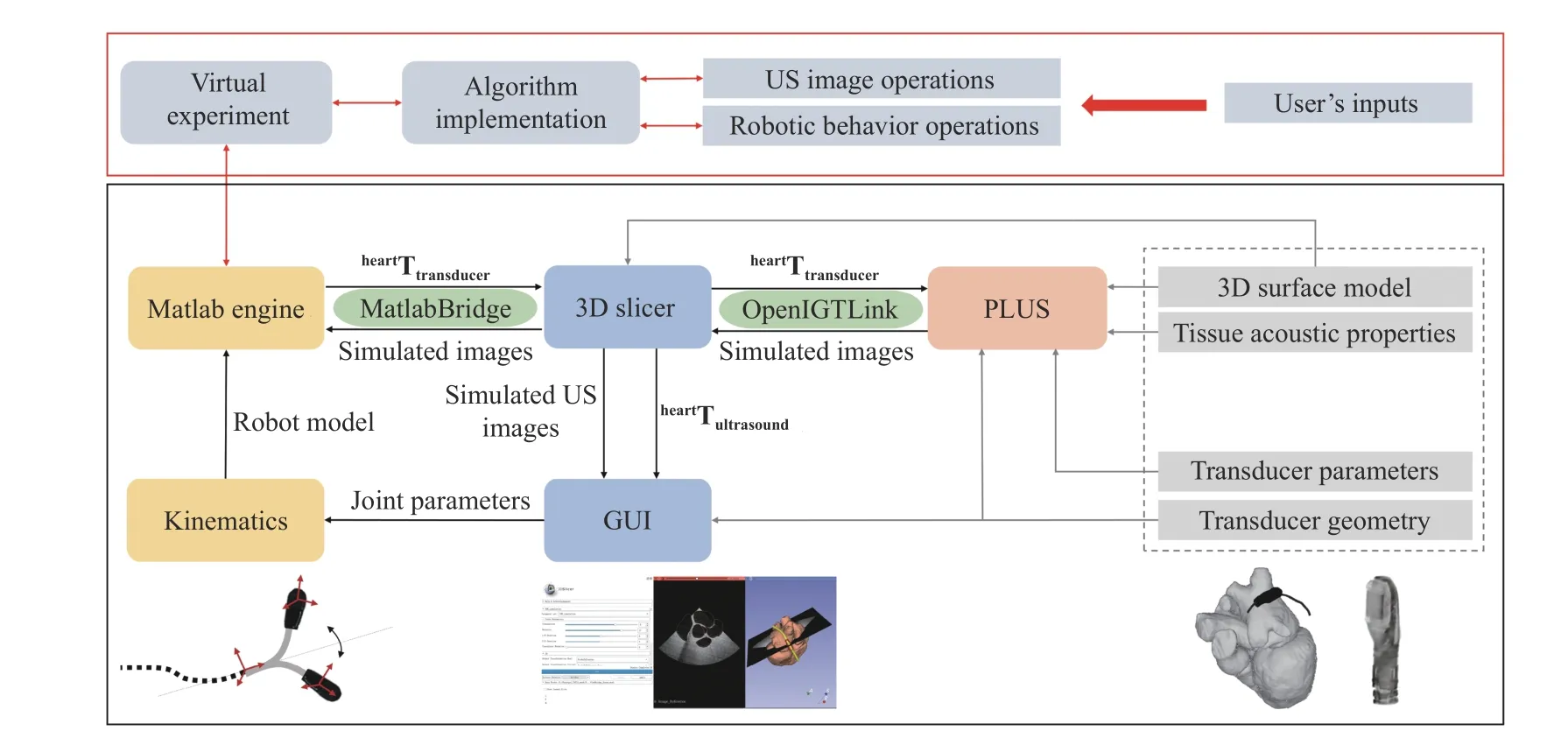
Fig. 4. Overview of the proposed virtual TEE parallel system. The diagram shown in the black block represents the fundamental function of the virtual system and the red block incorporates the advanced user-defined functions and algorithms.
The proposed system incorporates the use of 3D slicer (The Slicer Community, Ver. 4.10.2) as the main workspace and graphic user interface (GUI), Matlab engine to provide robotic control algorithms and customized functions, and PLUS(Public software Library for UltraSound imaging research,https://plustoolkit.github.io/) toolkit [20] to generate simulated ultrasound images. An example GUI is shown in Fig. 3 and the background architecture of the system is shown in Fig. 4.
On the main display section of the GUI shown in 3D slicer,a surface mesh model of the heart is displayed, along with the center line of the esophagus and the 3D model of the TEE probe head. In this study, a fully automatic whole heart segmentation method [21], based on shape-constrained deformable models, was employed to process a pre-scanned MR image volume in order to obtain cardiac chambers and great vessels. As a brief overview, the method utilized a 3D Hough transformation to localize the heart position, an image calibration method to compensate intensity variations in the MR images, and a multi-stage adaptation scheme to extract cardiac anatomies. The anatomy of the automatically segmented heart extracted from the MR image volume includes the four-chambers, the trunks of the aorta, the myocardium, the pulmonary artery, and the pulmonary veins.The center line of the esophagus was manually segmented directly in 3D slicer using its built-in segmentation module and the 3D model of the probe head was obtained from a separate CT scan.
The simulated ultrasound image based on the current posture of the transducer is also displayed on the GUI, as can be seen in Fig. 3. This is generated by an ultrasound image simulation module [22] implemented in PLUS. The communication between 3D slicer and PLUS, for transmitting the transducer posturesheartTtransducer, ultrasound image data,and the ultrasound image coordinatesheartTultrasound, is achieved using the OpenIGTLink [23], which is a module for network communication with external software/hardware using a specially designed protocol. For the current setup,localhost was utilized to create the transmission socket.
The interactive user control interface is generated using a standard command-line interface definition XML file based on the MatlabBridge extension module in 3D slicer. This allows the user to create customized inputs. For the fundamental function of the virtual system, the robotic joint parameters, i.e., translation, rotation, bending, and electronic steering, are listed as the default inputs. Additionally,customized inputs can be further created by editing the XML file. The Matlab module behaves as any other command-lineinterface module with the Matlab engine started automatically in the background. The extension allows running of Matlab functions and customized scripts directly from 3D slicer by taking the input from the data loaded into 3D slicer and visualizing the results in 3D slicer after the execution is completed.
By default, the kinematics of the TEE is provided as the basic Matlab function to be called from 3D slicer once the robotic joint parameters are changed. With the change of the input’s parameters, the transducer posture is calculated and transmitted back to 3D slicer to be updated in the GUI.Meanwhile, the transducer posture is also transmitted to PLUS and the ultrasound simulation module would take the input posture and compute a simulated ultrasound image based on the anatomical relationship of the heart, esophagus, and the transducer, as well as the pre-defined tissue properties and the transducer features. Moreover, customized user inputs,outputs, functions, and algorithms can be implemented and included into the current setup. The following subsections will explain the robot kinematics and the ultrasound simulation.Section IV will further demonstrate the add-on user-defined functions and algorithms that can be built on top of the basic architecture.
B. Robot Kinematics
Partially based on the work conducted in [24], this subsection summarized the details of the kinematics that is employed in the currently proposed virtual TEE system. The model describes the forward approach where a set of robotic motor parameters are given and the associated TEE view is obtained. This assumes the relative position information of the heart and esophagus is available. With the forward approach,the probe is modelled moving along the esophagus center line based on the parameter inputs. This includes three steps beginning with the transformation from the probe base coordinates to the heart coordinates (Fig. 5(a)), which is determined by the translational and rotational movements of the robot. The second step models the bi-directional bending of the probe tip, giving the transformation from the probe tip (transducer) coordinates to the probe base coordinates(Fig. 5(b)). Additionally, electronic steering of the ultrasound beam controlled by the ultrasound machine is modelled by rotating the 2D ultrasound plane. In the proposed virtual system, the parameters are adjusted via sliders in the software,and the resulting ultrasound image is updated.
The translational movement of the probe is constrained by the path of the esophagus. In practice, this is achieved by spline-based path interpolation [25] using the 3D point set of the esophagus center line. For each small segment of the esophagus, the method specifies four points at intervals along the path using the segmented points on the esophagus center line and defines a function that allows additional points within an interval to be calculated, as illustrated in Fig. 6. The point is controlled by a value that decides the portion of the distance between the two closest control points and its coordinate can be then calculated using the four control points (P0, P1, P2,and P3).
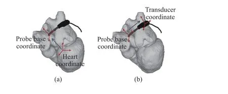
Fig. 5. Schematic illustration of the forward kinematic model. (a) Transformation from the probe base coordinates to the heart coordinates. (b) Transformation from the transducer coordinates to the probe base coordinates.
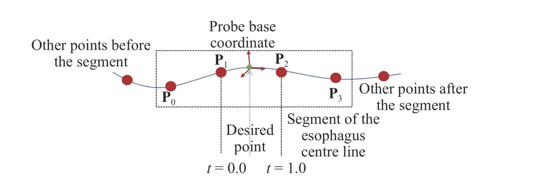
Fig. 6. Illustration of the spline interpolation for calculating an additional point in between the control points obtained from the esophagus segmentation.
In this study, the distance between the two nearest control points is uniformly divided into 10 pieces for the interpolation. Based on the interpolated points, the translation vector is obtained for the translational movement of the probe. The interpolated points allow the translational movement to follow the path of the esophagus and the distance is decided by the length along the curve. The default orientation of the probe base coordinates is decided to allow the transducer of the probe to point towards the heart center, as demonstrated in Fig. 7.
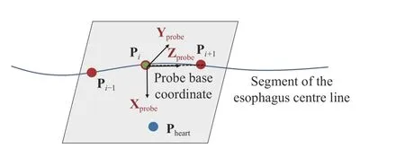
Fig. 7. Illustration of the default orientation of the probe base coordinates.
The Z-axis of the probe base coordinates Zprobeis determined by the current and the next interpolated points Pi,Pi+1.

The Y-axis of the probe base coordinates Yprobeis perpendicular to the plane that is determined by the interpolated point Pi–1, Pi, Pi+1, and the position of the heart Pheart. This is calculated by fitting Pi, Pi+1, and Pheartinto the plane and compute the normal vector.

As for the rotation of the probe about its long axis, the rotation matrix can be determined by the angle of the rotational mechanism φz. It should be noted that the rotational movement of the probe should always be relative to the probe base coordinates since the actuation of the rotation is applied to the handle of the TEE probe. This is explained in Fig. 8.
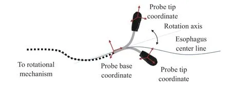
Fig. 8. Illustration of TEE robot’s rotational axis. The movement is relative to the probe base coordinate even if the probe is bent due to the driven mechanism being applied to the handle.
The bi-directional bending of the probe tip has previously been described and verified in [11]. The inputs are the rotation angle of the first bending knob (on the handle), φx, which controls the bending tip pitch in the posterior-anterior plane;and the rotation angle of the second bending knob (on the handle), φy, which controls the bending tip yaw in the leftright plane. The geometric illustration of the bending is shown in Fig. 9. The transformation matrix between the probe tip coordinates and the probe base coordinates is expressed as

where α is the angle between the bending plane and the X-Z plane, β is the bending angle in the bending plane, Lfis the length of the bending section of the probe tip, and Luis the length of the rigid section of the probe tip. R is the bending radius (R = Lf/β). In the matrix, Sx, Cx, and Vxdenote sin(x),cos(x), and (1–cos(x)), respectively.
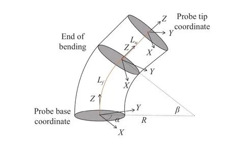
Fig. 9. Geometric illustration of TEE robot’s bi-directional bending.
The ratio of bending about the Y-axis to bending about the X-axis, α, is

A rotation of angle φxor φychanges the distribution of the length along the flexible part. The changes of length of the pull wires inside the probe handle are δ1= φxRpand δ2= φyRp,respectively. Rpis the relative radius of the rack and pinion mechanism where the pull wires are attached. The bending angle β is

where Rtis the cross-sectional radius of the TEE probe tip.
C. Simulated Ultrasound
With the known location of the probe tip coordinates, i.e.,where the TEE transducer is located, the ultrasound image coordinates is calculated based on the previous operations and the electronic steering angle θ:

The input to the ultrasound simulation module implemented in PLUS is the surface mesh model of the heart and a transformation representing the spatial relationship between the surface mesh and the simulated ultrasound image, i.e.,heartTultrasound. This allows the heart model to be transformed to the image coordinates. The intersecting region would then be calculated and displayed as a constant intensity binary image. During the processing, transducer parameters and the estimated material properties of the heart model are defined in a user-specified XML file read in by the simulator module.The workflow of the simulator is summarized in Fig. 10.
The simulated ultrasound image is generated based on the following steps [22]: locations of scan lines are calculated in the image coordinate system based on the specified size of the image, which has been pre-defined in the configuration file.These locations are then transformed to the model coordinate system. A binary space partitioning (BSP) tree is used to determine the intersecting points of the heart structures and the generated scan line. The intersection points divide the scan line into segments, which are then filled with a gray value.The intensity is calculated based on the material properties that are defined in the configuration file. The scan lines are then converted to a regular brightness-mode (B-mode)ultrasound image using the RF processing module of PLUS.The module processes the information in the scan lines and applies the appropriate spacing to formulate an ultrasound image.

Fig. 10. Workflow of the TEE image simulation module.

Fig. 11. Examples of standard 2D TEE views (ME 4-chamber, ME 2-chamber) for a patient defined in the virtual robotic TEE system with both the simulated ultrasound and the probe-heart positioning relationship shown. RA–Right Atrium; LA–Left Atrium; LV–Left Ventricle; RV–Right Ventricle.
IV. ExAMPLE USES AND CASE STUDIES
A. Use Example 1: Standard View Definition
A direct application of the proposed virtual robotic TEE system would be finding the potential probe poses and defining target ultrasound views. This could be done manually by the clinicians before the procedure if the robot is used.
By importing the patient’s segmented anatomical data and virtually controlling the TEE probe, 2D TEE standard views can be defined and the associated probe robotic manipulation parameters, along with the expected probe locations relatively to the heart, can be obtained. This is achieved by checking the output simulated ultrasound from manual interaction with the GUI. As an example, a standard patient MR image acquired with a Philips Achieva 1.5T MR scanner was set as the test heart-oesophagus model. Examples of 2D standard TEE views have successfully defined and are shown in Fig. 11. By comparing the defined views with the clinical guideline [19],it can be seen that the main structures, e.g., LA, RA, LV, RV for the ME 4-chamber view and LA, LV for the ME 2-chamber, are obtained and clearly observable. With the expected transducer location known and the potential tracking methods implemented during the procedure to track the TEE probe’s tip in the real physical system, semi-automatic acquisition using the physical robotic TEE system could be achieved. The possible tracking and coordinates registration methods to relate the pre-defined views and the real acquisitions have been studied in the previous work [12],which indicate an interaction between the virtual and physical systems.
Additionally, the use of 3D slicer and PLUS as the main workspace of the virtual robotic TEE system would allow several additional features to assist the real-time navigation.This includes interfacing position tracking data from various devices into the 3D slicer display and streaming the real TEE images obtained from the ultrasound machine into the 3D slicer display. With these features, the current virtual robotic TEE system can be further developed to show the real-time transducer locations and the real TEE images, in comparison with the expected transducer location and the simulated image.
B. Use Example 2: Customized View Optimization
This example aims to show the use of the virtual environment to do customized view optimization in an interactive way with the inputs from both the operator and the computational method before the procedure when using the robot, i.e., automatically find expected probe poses based on the clinical requirements of certain anatomical structures. This would reduce the operator’s workloads and requirements of experience when using the TEE robot semi-automatically.
To highlight this capability, we provide an example with two case studies. The task focuses on the minimally invasive cardiac surgery guided by 2D TEE. In the first case, we targeted at the use of TEE robot to help the navigation of guide wire and subsequent threading of venous cannula, as described in [26]. This requires the use of bicaval or modified bicaval view so that the left atrium (LA), right atrium (RA),superior vena cava (SVC) and inferior vena cava (IVC) can be inspected. In the second case, we targeted at the use of TEE robot to help transcatheter aortic valve implantation, as described in [27]. In this application, mid-esophagus aortic valve long-axis (ME aortic valve LAX) view is expected so that the delivery sheath can be seen across the aortic valve with LA and left ventricle (LV), right ventricle (RV), and ascending aorta (Asc AO) visible. Using the proposed virtual robotic TEE system with an additional customized Matlab script, interactive automatic view definitions of bicaval and ME aortic valve LAX views were obtained based on the following steps:

Fig. 12. Flow diagram showing the steps of the automatic view optimization example presented in this paper using the mixed integer GA optimization.
1) Fiducial points were manually placed using the Markup module in 3D slicer. These are to indicate the structures to be shown on a 2D view. For this example, fiducial points are placed at the center of the IVC, SVC, and RA for the bicaval view and placed at the center of aortic valve and mitral valve for the ME aortic valve LAX view.
2) Fiducial points locations in the heart coordinatesheartP are transferred to the ultrasound image coordinatesultrasoundP based on the TEE transducer locations. This step is achieved by the Matlab script called by the 3D slicer when there are changes in these parameters.
3) Customized objective functions are defined to constrain the expected view based on the user-defined fiducial points.The object could be set so that the fiducial points are on the expected TEE view plane, at the center line of the view plane,or both. The mathematical form can be easily obtained using the –X, Y, and Z components of the fiducial point’s coordinatesultrasoundP.
4) Optimization tools in the Matlab engine can be called by the 3D slicer based on the additional customized script to optimize the robotic joint parameters until the objective functions are minimized.
In this example, the mixed integer generic algorithm (GA)was utilized. Comparing with the basic GA algorithm, the creation, crossover, and mutation functions enforce variables to be integers. The algorithm attempts to minimize a penalty function, which includes a term for infeasibility. This penalty function is combined with binary tournament selection to select individuals for subsequent generations. Detailed explanation of the algorithm can be found in [28], [29]. The flow diagram of the interactive automatic view optimization is shown in Fig. 12. Several other optimization algorithms can be also employed, e.g., direct search method, interior-point method, and trust-region reflective method. These will not be detailedly covered in this paper. The results of this example can be seen in Fig. 13. The penalty values over generations are displayed and the resulted optimized views are shown.
Qualitatively, it is observed that the optimized bicaval view has successfully included the expected main anatomical features according to the clinical guideline [19], i.e., LA, RA,IVC, and SVC. The optimized ME aortic valve LAX view has also successfully included the expected anatomical features according to the clinical guideline [19], i.e., LA, LV, RV, and Asc AO. This example shows the extended use of the proposed virtual robotic TEE system to define standard views in a semi-automatic approach for less-experienced clinicians and demonstrates the effectiveness of the method.
Quantitatively, the fiducial points locations in the resulted ultrasound image coordinatesultrasoundP were calculated. The–Y (perpendicular to the ultrasound image plane) and –Z(along the long axis of the probe tip) components of the fiducial point’s coordinates were analyzed. For the optimized bicava view, fiducial points coordinates were quantified respectively for points 1, 2, and 3. It can be observed that the–Z component of fiducial point 1 is close to zero, indicating point 1 was optimized to be at the center region of the view, as expected by the formulation of the objective function. The absolute in-plane error for the fiducial point 1 (–Z component)is 2.24 mm. For all three points, the –Y components are close to zero, indicating the ultrasound plane has been optimized to be at an acceptable desired location. The mean absolute offplane error for the three fiducial points (–Y component) is 0.89 mm. Similar results can be found for the optimized ME aortic valve LAX view with fiducial points 1 and 2 quantified. The absolute in-plane error for the fiducial point 1 (–Z component)is 0.04 mm and the mean absolute off-plane error for the two fiducial points (–Y component) is 0.35 mm.
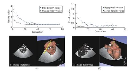
Fig. 13. Results of the automatic view optimization example presented in this paper using mixed integer GA to optimize the (a) bicava view with the fiducial points positioned at IVC, SVC, and the center of RA and (b) ME aortic valve LAX view with the fiducial points positioned at the center of aortic valve and mitral valve. The upper row shows the changes of the penalty values used in the GA optimization over the growing of generations where the convergences were achieved.
C. Use Example 3: In-Silico Robotic Control Experiments
In addition to the view definition and optimization, the proposed virtual robotic TEE system can be used to perform in-silico experiments for the evaluation of robotic control algorithms to facilitate the calculation of probe poses in real time. This helps the realization of the automatic TEE during the scan as it can adjust the probe pose in real time if the corresponding data are sensed and feedback from the physical environment to the simulation environment.
Additionally, this is also helpful for the further developments of the robot as it can test different control schemes in a simple cost-free way. In fact, to test some algorithms with the real physical robotic systems could be challenging for the intra-operative ultrasound. This is because the in-vivo testing normally requires a long period of preparation time in terms of robot safety, ethics, and clinical approval, while at the same time the in-vitro tests are limited by the availability of customized phantoms.
In this example, we used the proposed virtual robotic TEE system to realize a simple Jacobian-based control scheme to calculate probe poses. The example targets at the trans-septal punctual, the atrial septum defect (ASD) closure, or patent foramen ovale (PFO) closure, where catheters could be guided by TEE to pass through the atrial septum. The selected view to analyze is the ME bicaval view and the task is defined as: the initial location of the TEE transducer was achieved by the manual control of the robot and only the bi-directional bending axes are further actuated locally to fine-tune the 2D ultrasound view so the catheter can be seen on the image plane and its tip is positioned at the center of the view. Both the catheter tip and the TEE probe’s locations are assumed to be tracked by either image-based methods or sensor-based tracking methods. These are intrinsically known in the virtual environment.
Considering the differential kinematics, the joint space parameters for the bi-directional bending are defined as R =[α, β]T. The velocity skew of the probe tipTransducerV = [v,ω]T, expressed in the probe tip coordinates, is determined by the robotic Jacobian JR. The Jacobian for angular velocity can be extracted from the skew-symmetry matrix, which is obtained from the multiplication of the partial derivative and the transpose of the rotation matrixProbeBaseRTransducer:
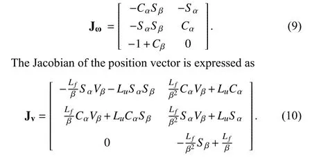
Similarly, Sx, Cx, and Vxdenote sin(x), cos(x), and(1–cos(x)), respectively. The resulting robotic Jacobian is expressed as JR= [Jv, Jω]T. The control scheme for adjusting the probe bi-directional bending pointing to the catheter can be further determined by relating differential changes of the catheter tip’s locations to differential changes in the configuration of the robot. In the virtual experiment, both the TEE probe and the catheter’s locations are known, giving the coordinates of the catheter tip in the probe base coordinate frameProbeBaseP as the result. The following relationship is obtained based on the differential kinematics:

˙
where S(TransducerP) is the skew-symmetry matrix ofTransducerP. The calculated Jacobian, relating the changes of robotic joint parameters to the changes of the catheter tip location in the probe tip coordinates, is therefore obtained, as detailed in [30].
With the differential kinematics, we have considered a simple control scheme (Fig. 14) implemented as an additional Matlab function to be called by 3D slicer when the catheter’s location is moved. A virtual 3D catheter model is represented by a small cylinder and its acoustic properties are estimated and configured by the PLUS. The control scheme intends to position the catheter onto the ultrasound plane and locate its tip to the center of the view. An example of the successful implementation is shown in Fig. 15 where movements of the catheter would result in the movements of the TEE probe to keep the catheter visible in the simulated ultrasound image and position its tip to the approximate center region.
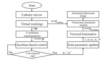
Fig. 14. Flow diagram showing the steps of the automatic catheter pointing example presented in this paper using the Jacobian-based control scheme.
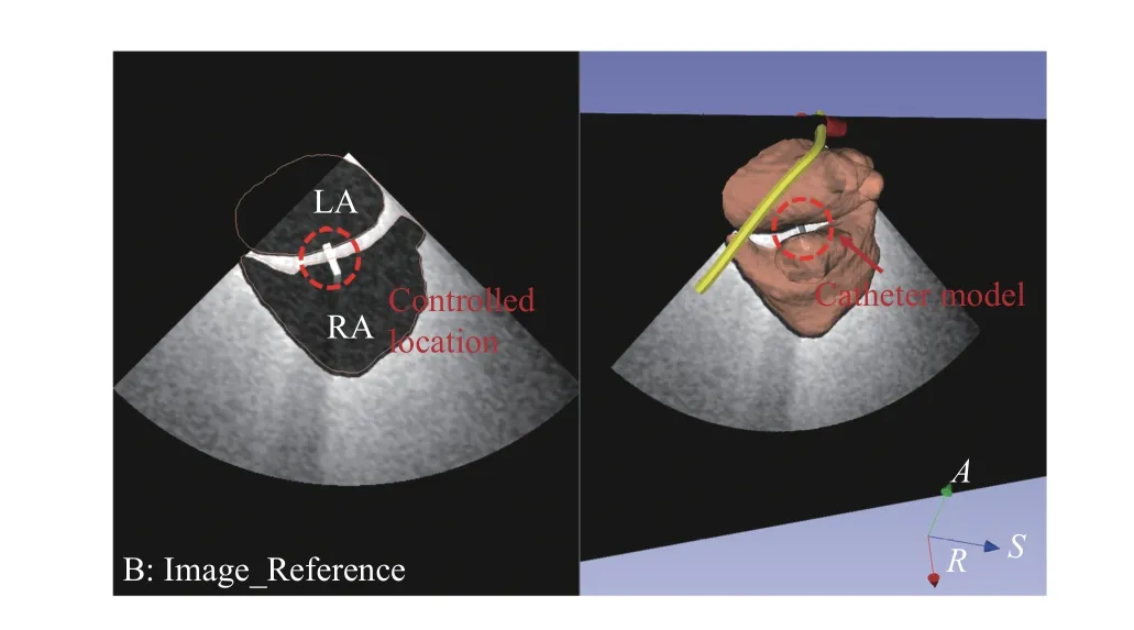
Fig. 15. Example Jacobian-based control result of the simulated ultrasound image with the virtual catheter visible on the plane and in the center region.
As a proof-of-concept test, 10 simulated positions of the catheter were generated during a trans-septum procedure from LA and RA. The TEE probe was automatically adjusted based on the method to keep the catheter in the ultrasound plane and be at the center region. Same as the method introduced in Section IV-B, the catheter tip’s locations in the resulted ultrasound image coordinatesultrasoundP were calculated with its –Y, and –Z components analyzed. The mean absolute inplane error (the –Z component) is 0.08 mm and the mean absolute off-plane error (–Y component) is 0.12 mm, both are close to zero. This proves the effectiveness of the proposed approach. Further details of the algorithm itself can refer to our previous work [30].
V. DISCUSSIONS AND CONCLUSION
Motivated by the demands in the research area of robotic intra-operative ultrasound systems, this paper introduces the developments of a virtual computational environment to represent the physical use of a recent developed TEE robot based on the concept of parallel system and ACP. The proposed virtual system includes the use of 3D slicer as the main workspace and GUI, Matlab engine to provide robotic control algorithms and customized functions, and PLUS toolkit to generate simulated ultrasound images. The use of 3D slicer enables interfacing with many other powerful modules developed for image analysis, visualization and navigation and the PLUS toolkit would support further developments of the virtual system to integrate tracking data from physical devices and real TEE images streamed from ultrasound machines. Therefore, the proposed virtual system has great potential to be further developed for customized applications.
The proposed workflow for developing the virtual system introduced in this paper was based on the TEE robot although it can be also adapted for the robotic TRUS systems, robotic ICE systems, or other robotic intra-operative systems using the same architecture as introduced in Fig. 4. To do so, the corresponding kinematics, the physical model of the probe,the anatomical data, and the configuration of the customized control interface need to be provided.
The current proposed virtual robotic TEE system can include the customized heart and esophagus model, simulate the basic kinematic motion of the transducer, and compute the simulated ultrasound images. The integration of the Matlab engine allows customized algorithms to be directly called from the GUI. Considering the concept of ACP, the current configuration has implemented the artificial system, allowed for the computational experiments, and can be used for parallel execution. These features were demonstrated with three examples in this paper to show the capability of this system. This includes the pre-planning, navigation, and realtime probe pose adjustment, which represent the possible interaction, management, and control between the physical and the artificial systems. The last example introduces the capability of doing in-silico robotic control experiments using the proposed system when including additional Matlab functions to be called. As this paper focuses on introducing the virtual system and its feasibility in different applications,more detailed analysis of a specific algorithm and computational details for each case are not treated as our primary concerns.
Although the proposed virtual system can represent the physical robotic TEE system to a certain extent, several limitations exist which could influence the performance. The biomechanical interactions between the TEE probe head and the esophagus were not modeled in the current kinematics.The proper representation of the stomach is not yet implemented. Moreover, acoustic properties could be finetuned and assigned differently to the different portions of the heart segmentation, which will improve the visual effects of the simulate ultrasound. In addition to the abovementioned limitations, the current virtual generated image has not yet included realistic noise effects comparing to the real ultrasound. The heart was modeled as a static object which also differs from the real scenario. However, as the virtual environment is aimed to support pre-planning, navigation and semi-automatic use of the robot for its long-term prospect,whether it is necessary to include these effects would still need more clinical evidence.
Despite these limitations, the current study has successfully extended the parallel system and ACP theory to a specific medical robotic research topic and demonstrated the detailed methods for implementing a virtual environment to represent physical systems of the robotic intra-operative ultrasound. By exploring the use of the virtual environment, values of the proposed system to support human operator in defining desired ultrasound views and finding the corresponding probe poses are well illustrated by three examples. This would be an important step forward to complete the workflow and support robotic-assisted automatic ultrasound, as proposed in [12].Our future works will focus on resolving the current limitations of the virtual system and employing the current proposed system to evaluate other advanced control strategies for the TEE robot to support the future clinical use of the physical robot.
杂志排行
IEEE/CAA Journal of Automatica Sinica的其它文章
- Review of Research and Development of Supernumerary Robotic Limbs
- Control of Non-Deterministic Systems With μ-Calculus Specifications Using Quotienting
- Decentralized Dynamic Event-Triggered Communication and Active Suspension Control of In-Wheel Motor Driven Electric Vehicles with Dynamic Damping
- ST-Trader: A Spatial-Temporal Deep Neural Network for Modeling Stock Market Movement
- Total Variation Constrained Non-Negative Matrix Factorization for Medical Image Registration
- Sampled-Data Asynchronous Fuzzy Output Feedback Control for Active Suspension Systems in Restricted Frequency Domain
