Decentralized Dynamic Event-Triggered Communication and Active Suspension Control of In-Wheel Motor Driven Electric Vehicles with Dynamic Damping
2021-04-13IftikharAhmadXiaohuaGeSeniorMemberIEEEandQingLongHanFellowIEEE
Iftikhar Ahmad, Xiaohua Ge, Senior Member, IEEE, and Qing-Long Han, Fellow, IEEE
Abstract—This paper addresses the co-design problem of decentralized dynamic event-triggered communication and active suspension control for an in-wheel motor driven electric vehicle equipped with a dynamic damper. The main objective is to simultaneously improve the desired suspension performance caused by various road disturbances and alleviate the network resource utilization for the concerned in-vehicle networked suspension system. First, a T-S fuzzy active suspension model of an electric vehicle under dynamic damping is established. Second,a novel decentralized dynamic event-triggered communication mechanism is developed to regulate each sensor’s data transmissions such that sampled data packets on each sensor are scheduled in an independent manner. In contrast to the traditional static triggering mechanisms, a key feature of the proposed mechanism is that the threshold parameter in the event trigger is adjusted adaptively over time to reduce the network resources occupancy. Third, co-design criteria for the desired event-triggered fuzzy controller and dynamic triggering mechanisms are derived. Finally, comprehensive comparative simulation studies of a 3-degrees-of-freedom quarter suspension model are provided under both bump road disturbance and ISO-2631 classified random road disturbance to validate the effectiveness of the proposed co-design approach. It is shown that ride comfort can be greatly improved in either road disturbance case and the suspension deflection, dynamic tyre load and actuator control input are all kept below the prescribed maximum allowable limits, while simultaneously maintaining desirable communication efficiency.
I. INTRODUCTION
THE automotive industry has witnessed a substantial increase in the popularity of advanced technologies such as replacement of the internal combustion engine vehicles with electricity driven motors. Electric vehicles provide a promising solution to the challenges offered by the internal combustion engine vehicles such as environmental friendliness and energy efficiency, and therefore considerable research has been conducted on the development and optimization of electric vehicles [1]. Based on the propulsion system, electric vehicles can be roughly classified into centralized motor driven electric vehicles and in-wheel-motor(IWM) driven electric vehicles. Specifically, IWM configuration offers several advantages over centralized configuration (similar to the conventional internal combustion vehicles), such as generation of precise and fast torque, while not effecting the driveshaft stiffness. Different control strategies for electric vehicles, including vehicle dynamics control [2], steering control [3], and lateral control [4], [5],have been developed. However, installing a motor in a wheel results in an increase in the unsprung mass which in turn aggravates the road holding and ride comfort performance.Therefore, the influence of an IWM on ride comfort and vehicle safety is required for suitable treatment in suspension system design. For example, to improve road holding performance, a dynamic-damping in-wheel motor driven system is developed in [6] such that the system suspends the shaftless direct drive motor and isolates it from the unsprung mass.
Note that road holding and ride comfort are in conflict with each other. Such a conflicting issue therefore needs to be carefully addressed during suspension system analysis and design. Among its other counterparts, active suspension has been acknowledged as a promising means to provide a compromise between these contradictions. Naturally, much attention has been paid to the development of active suspension systems. For example, several active control techniques, such as T-S fuzzy control [7], [8], robustH∞control [9], [10], linear optimal control [11], neural-networkbased adaptive control [12], [13], have been developed to improve the suspension control performance. To overcome the disadvantages of an IWM in electric vehicles, active suspension under dynamic damping also has been intensively studied [14]–[16] with an aim to manage the trade-off between ride comfort and road holding performance of IWMdriven electric vehicles. For example, by installing a dynamic damper, a vibration mitigation method was presented in [16]for electric vehicles with an in-wheel switched reluctance motor. On the other hand, to obtain better disturbance attenuation performance, the active suspension control design can be explored in a constrained frequency range rather than the entire frequency range [15], [17], [18]. For example, the finite-frequency H∞control problem of active suspension system was studied in [17], where the H∞norm of the disturbance to control output is minimized in a finite frequency range to preserve ride comfort improvement. Based on static output feedback, a robust finite-frequency H∞active suspension control approach was proposed in [18] to improve the ride comfort performance of the suspension system while preserving the hard constraints.
There has been a considerable growth in intra-vehicular networked control systems with the ever-increasing demand of vehicle safety and performance in modern vehicles. A key component is the network architecture that connects the intravehicular control system components, such as sensors,actuators and electronic control units. Automotive industry is continuously striving for substantial progress of wired and wireless data communication infrastructure. A widely adopted technology is the controller area network (CAN) that requires the data to be digitized and sampled before broadcasting and transmission over the CAN buses. Today’s autonomous vehicles have a myriad of applications and tasks enabled by CAN, which makes the essentially finite CAN resources more scarce than ever. However, most of existing results on vehicle active suspension control have assumed continual data transmissions among sensors, controllers and actuators. Due to the limited in-vehicle network resources, the data transmissions to be broadcast and transmitted over CAN should be wisely selected and scheduled. Traditionally, a periodic (or time-triggered) communication mechanism has been widely adopted to perform the data transmissions and/or the executions of control tasks at only discretized instants,leading to the so-called sampled-data control for vehicle active suspension systems [10], [19]–[21]. Nevertheless, the sampling period under the conventional sampled-data control is often pre-set in the worst scenario to guarantee the desired system performance. Furthermore, a small sampling period results in a large number of redundant sampled data transmissions, causing excessive occupancy of the limited network resources and also the frequent changes in the actuator states (or known as the actuator attrition) at every sampling instant.
An alternative communication mechanism called an eventtriggered communication mechanism has been put forward in the literature to eliminate the limitation of the traditional periodic communication mechanisms. Under such an eventtriggered mechanism, data transmissions are invoked only after the occurrence of some well-defined events. As such,event-triggered communication mechanisms can generally achieve significantly improved communication efficiency while not sacrificing too much of desired system performance.Generally, the threshold parameter employed in an event trigger decides how often current data packets should be transmitted [22], [23]–[25]. However, it is noteworthy that most existing event-triggered communication mechanisms employ a pre-set constant threshold parameter in the event trigger design, and thus are often regarded as static eventtriggered communication mechanisms (e.g., [26]–[29]).However, there are several practical scenarios that fixing the threshold parameter permanently is not preferable; see the justifications in [30], [31] and also the recent surveys [25],[32]. By inserting some extra internal dynamic variable into a triggering condition, the so-called dynamic event-triggered communication mechanism was developed for various networked dynamical control systems [25], [33]–[36]. On the other hand, an adaptive event-triggered control problem was addressed in [37] for vehicle active suspension system subject to uncertainties and actuator faults. The threshold parameter selected for the event trigger was adaptively adjusted with an aim to reduce data transmissions as much as possible. In [9], a dynamic event-triggered H∞control approach was developed for active suspension systems. In [38], an adaptive hybrid event-triggered mechanism was studied to tackle the reliable active suspension control of a cloud-aided quarter-car suspension system in a finite frequency range. A common feature of the designed event triggers in [9], [38] is that they involve a non-increasing dynamic threshold parameter and thus release more sampled data packets than the traditional static event trigger with a fixed threshold parameter.Furthermore, it should be also pointed out that the eventtriggered active suspension control studies [9], [37], [38] are all conducted in a centralized manner, which means that the full state of the concerned vehicle suspension system has to be measured by a single sensor and a global event trigger is required to verify the triggering condition at the same time.Apparently, the complete state information of the vehicle suspension system may not be available for the single sensor at all times due to the limited sensor energy and sensing/computing capabilities. In this sense, a decentralized event-triggered communication mechanism in a multi-sensor setting is highly preferable to allow each sensor’s data transmissions to be selected independently. To the best of the authors’ knowledge, the decentralized dynamic eventtriggered communication and active suspension control codesign problem for IWM electric vehicles with dynamic damping has not been explored in the existing literature,which motivates this study.
In this paper, we address the dynamic event-triggered active suspension control problem for an uncertain IWM electric vehicle with dynamic damper and actuator fault. To achieve a better trade-off analysis between suspension performance requirements and communication resource usage, the active suspension control issue of the IWM electric vehicle is accomplished under novel decentralized and centralized dynamic event-triggered communication mechanisms. The main contributions of the paper are summarized as follows.
1) A general active suspension model is established for an in-vehicle networked 3-degrees-of-freedom (DOF) quarter IWM electric vehicle subject to uncertain sprung mass,unsprung mass and dynamic damper mass, uncertain actuator fault, and intermittent data transmissions.
2) A novel decentralized dynamic event-triggered communication mechanism is developed to determine independently whether or not each sensor’s sampled data packets should be broadcast and transmitted over the CAN bus. When all system state components are simultaneously measurable, two centralized dynamic event-triggered communication mechanisms are also proposed to regulate the sensor’s data transmissions.
3) New co-design criteria for the desired dynamic eventtriggered mechanisms and the admissible active suspension controllers are derived to guarantee prescribed suspension performance and satisfactory communication efficiency.
Furthermore, comprehensive comparisons between different event-triggered mechanisms and various road disturbance responses of an uncertain quarter vehicle suspension model are presented to substantiate the merits of the proposed results.
The rest of the paper is organized as follows. Section II provides the problem formulation. Section III performs the stability and performance analysis as well as the co-design of dynamic event-triggered communication mechanisms and fuzzy active suspension controller. Section IV presents the comprehensive simulations for verifying the derived main results. Section V concludes the paper.

II. PROBLEM FORMULATION
A. In-Wheel ADM-Based Active Suspension System
A 3-DOF quarter vehicle active suspension system with an advanced-dynamic-damper-motor (ADM) is shown in Fig. 1,where ms(t) represents the uncertain suspended mass of a quarter vehicle body, mu(t) represents the uncertain nonsuspended mass, i.e., mass of a single tyre, spring and damper,mr(t) represents the uncertain mass of the ADM, csis the sprung mass damping coefficient, cris the ADM damping coefficient, ctis the tyre damping coefficient, ksis the suspension stiffness, ktis the tyre stiffness, kris the ADM stiffness, u(t) (correspondingly, uf(t)) is the control input in fault-free (correspondingly, faulty) case, xs(t) is the sprung mass displacement, xu(t) is the unsprung mass displacement and xr(t) is the ADM displacement.
Denote by x1(t)=xs(t)−xu(t) the suspension deflection,x2(t)=xr(t)−xu(t)the dynamic vibration absorber deflection,x3(t)=xu(t)−xt(t) the tyre deflection, x4(t)= x˙s(t) the sprung mass speed, x5(t)= x˙u(t) the unsprung mass speed, and x6(t)= x˙r(t)the dynamic vibration absorber speed,respectively. By the Newton’s second law, the dynamical model of the suspension system is given by r suspension system is beneficial for reducing the sprung mass acceleration near the resonance of the unsprung mass as compared with the conventional electric vehicle suspension system.
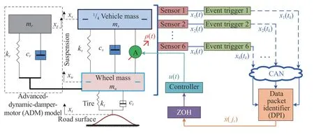
Fig. 1. A decentralized event-triggered communication mechanism for invehicle networked active suspension with an ADM.
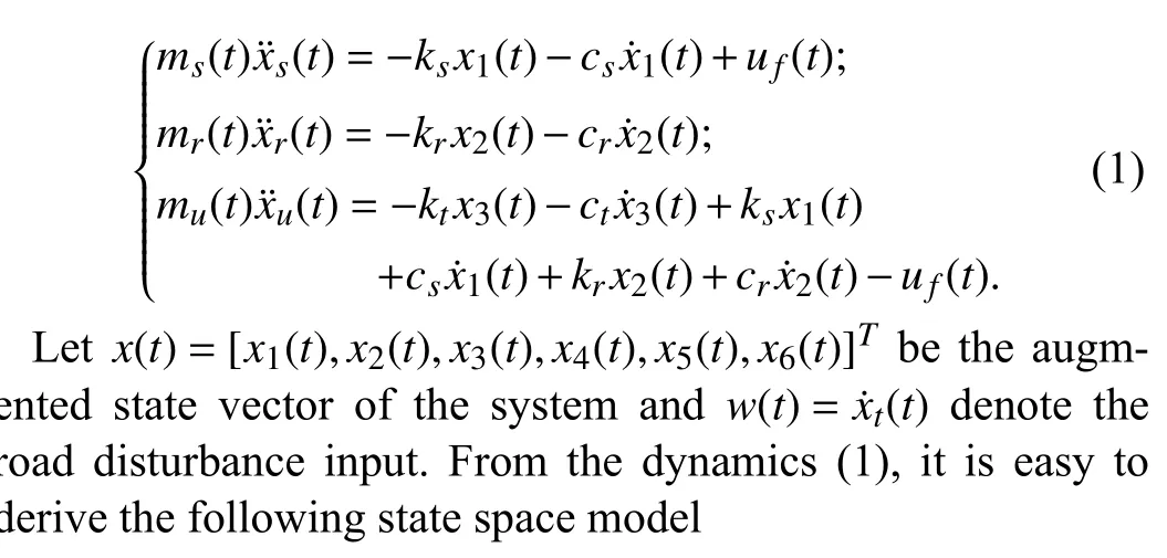
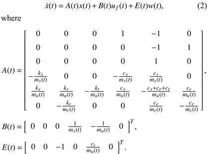
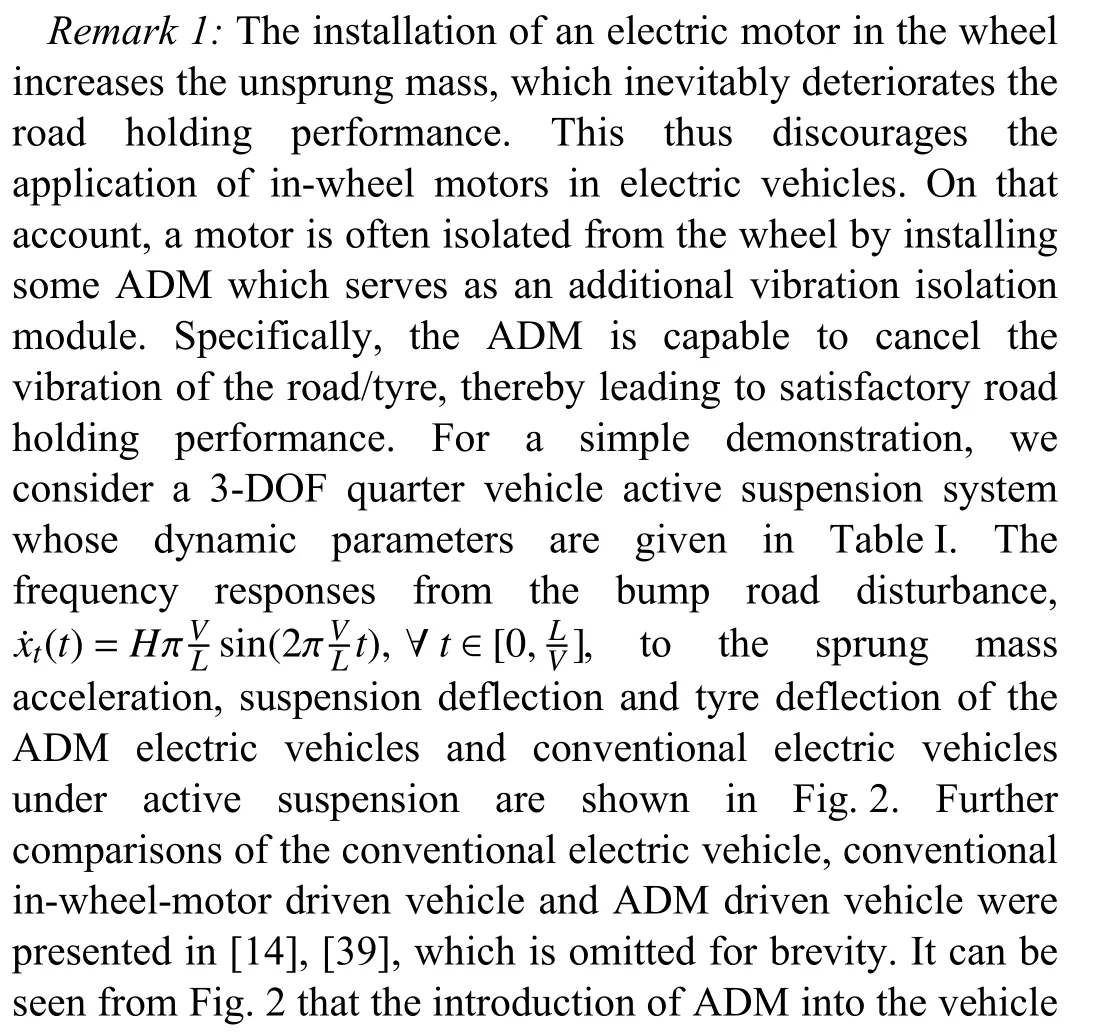

TABLE I SUSPENSION SYSTEM PARAMETERS
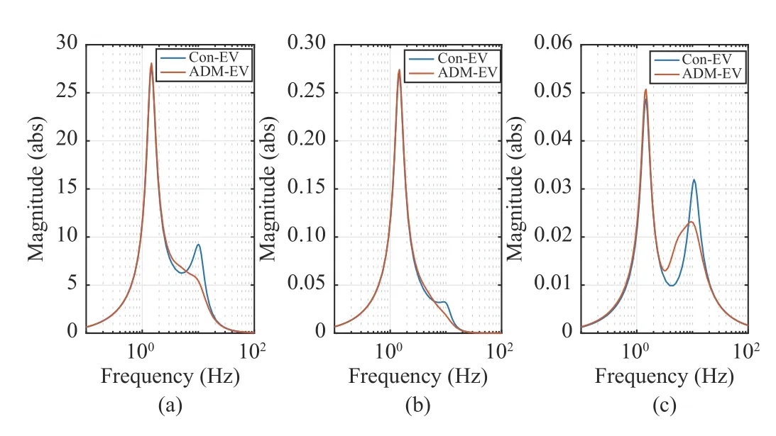
Fig. 2. Frequency responses of (a) Sprung mass acceleration; (b) Suspension deflection; (c) Tyre dynamic force, for a conventional electric vehicle(Con-EV) and an advanced-dynamic-damper-motor electric vehicle (ADMEV).
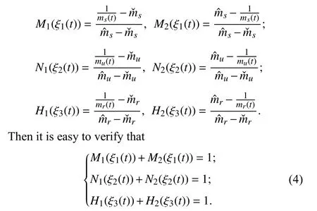
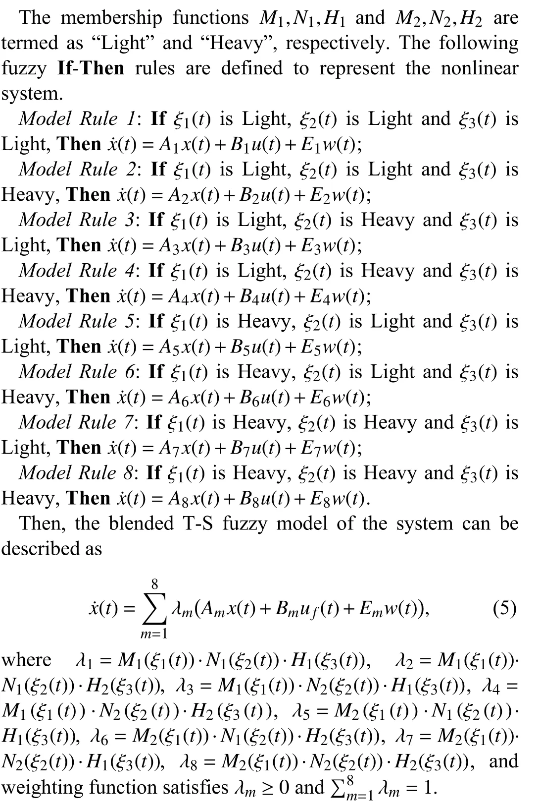
B. T-S Fuzzy Modeling


C. Actuator Fault
Under the actuator fault, the actual control input uf(t) can be modeled as

where ρ(t) represents the uncertain fault in the actuator, and the parameters ρLand ρUcharacterize the lower and upper bounds of the fault, respectively. Note that the above uncertain fault model incorporates the following three particular cases of actuator operating scenarios:
1) when ρL=ρU=1, then ρ(t)=1 and the actuator is in the normal mode of operation;
2) when 0<ρL<ρU<1, then 0<ρ(t)<1 and the actuator loses its effectiveness; and
3) when ρL=ρU=0 , then ρ(t)=0 and the actuator is fully blocked.

D. A Novel Decentralized Dynamic Event-Triggered Communication Mechanism
Traditionally, a single sensor is adopted to observe and measure the whole system state x(t). In this sense, the sensor is required to access all six state components x1(t),...,x6(t) at all continuous times t ∈R. Apparently, this may be inapplicable or even invalid for CAN-based vehicle suspension systems because of at least the following three reasons: 1) a single sensor is more susceptible to sensor failure or malfunction; 2) a single sensor inevitably exhibits high energy expenditure for measuring all six system state components; and 3) CAN represents a typical digital and broadcasting network medium that permits only sampled data packets. As a result, a decentralized multi-sensor-based sampling configuration is more preferable for the concerned CAN-based vehicle suspension system. Furthermore, to avoid excessive consumption of intra-vehicular limited communication resources, a decentralized dynamic event-triggered mechanism is introduced to transmit only ‘necessary’ sampled data while preserving the desired suspension performance. We introduce the following notations for a better understanding of the proposed decentralized dynamic event-triggered communication paradigm of the CAN-based vehicle suspension system.
• {mh|m ∈N}: This set defines the sampling instants of the system state components, where h>0 is the constant sampling period. Specifically, six sensors are deployed to monitor and sense the vehicle state components. For any i={1,...,6}, sensor i periodically samples the continuous-time system state component xi(t) into xi(mh) at instant mh. The current sampled-data xi(mh) and its time-stamp m are then encapsulated into a single data packet (m,xi(mh)) for possible network transmission. Whether or not the sampled data packet(m,xi(mh))should be broadcast and transmitted is determined by the triggering mechanism.


Algorithm 1 Mechanism of DPI h>0 Ts r=0 jr =0ti0=0 new_id=0 1: Given and the runtime , set , , ,m=1:1: Ts 2: for do i=1:6 h 3: for do(tik,x(tikh)) ith mh 4: if A new data packet from the event trigger arrives at DPI at time then new_id=1 5: Set(tik,x(tikh))6: Update the DPI with the newly arrived packet 7: end if 8: end for new_id=1 9: if then r=r+1 jr ←mh 10: Set and ˜x(jr)←col{x1(t1kh),x2(t2kh),...,x6(t6kh)}11: Generate and output the new data 12: Reset 13: end if 14: end for new_id=0
For each sensor i, i ∈{1,...,6}, we are now in a position to develop a decentralized dynamic event trigger i, as shown in
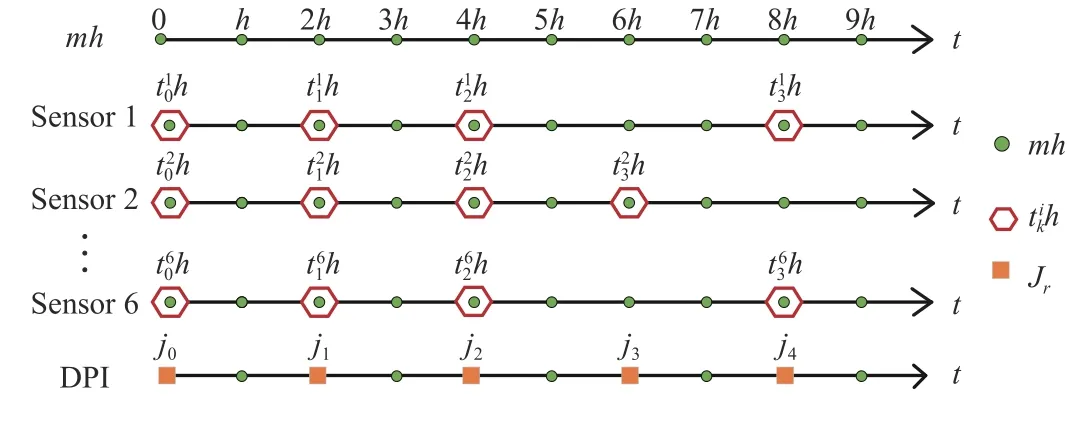
Fig. 3. A timing diagram of sensor data sampling, triggering and arriving.

E. A Decentralized Event-Triggered Fuzzy Controller
We are interested in constructing and designing the following event-triggered fuzzy state feedback controller
Control Rule 1: If ξ1(t) is Light, ξ2(t) is Light and ξ3(t) is Light, Then uf(t)=ρ(t)K1x˜(t);
Control Rule 2: If ξ1(t) is Light, ξ2(t) is Light and ξ3(t) is Heavy, Then uf(t)=ρ(t)K2x˜(t);
Control Rule 3: If ξ1(t) is Light, ξ2(t) is Heavy and ξ3(t) is Light, Then uf(t)=ρ(t)K3x˜(t);
Control Rule 4: If ξ1(t) is Light, ξ2(t) is Heavy and ξ3(t) is Heavy, Then uf(t)=ρ(t)K4x˜(t);
Control Rule 5: If ξ1(t) is Heavy, ξ2(t) is Light and ξ3(t) is Light, Then uf(t)=ρ(t)K5x˜(t);
Control Rule 6: If ξ1(t) is Heavy, ξ2(t) is Light and ξ3(t) is Heavy, Then uf(t)=ρ(t)K6x˜(t);
Control Rule 7: If ξ1(t) is Heavy, ξ2(t) is Heavy and ξ3(t) is Light, Then uf(t)=ρ(t)K7x˜(t);
Control Rule 8: If ξ1(t) is Heavy, ξ2(t) is Heavy and ξ3(t) is Heavy, Then uf(t)=ρ(t)K8x˜(t).
Therefore, the blended T-S fuzzy controller is given as

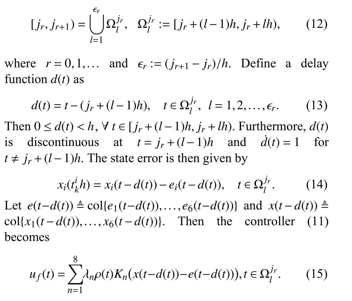
where Knare the controller gains to be designed. Furthermore,the arriving intervals at the ZOH can be divided into the following equidistant subintervals
F. Suspension Performance Requirement s
The aim of this paper is to preserve the following performance requirements [10], [14], [17], [19] for the concerned uncertain IWM quarter vehicle active suspension system in the subsequent analysis and design procedures.
1)Ride comfort: A key feature of the suspension system is to ensure passenger’s ride comfort. Ride comfort can be defined by the vehicle body vertical acceleration x¨s(t)= x˙4(t),which is considered as a performance output of the suspension system (5). This is given by

G. Problem Description
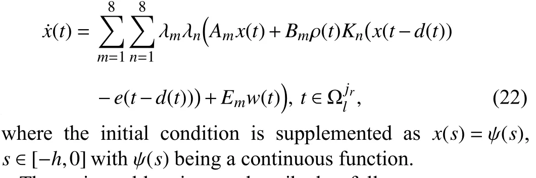
Substituting the controller (15) into the system (5), we have the resulting closed-loop system as follows
The main problem is now described as follows.
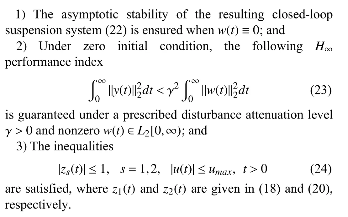
Problem 1: The control objective is to design an appropriate event-triggered fuzzy controller in the form of (15) under the desired decentralized dynamic event-triggered mechanism (9)(s.t. (10)) such that
III. MAIN RESULTS
A. Stability and Performance Analysis: The Decentralized Case
In this section, the feasibility of the concerned problem is studied formally under the decentralized dynamic eventtriggered communication mechanism (9), followed by a sufficient condition that ensures the asymptotic stability of the closed loop suspension system (22) under the prescribed performance requirements.
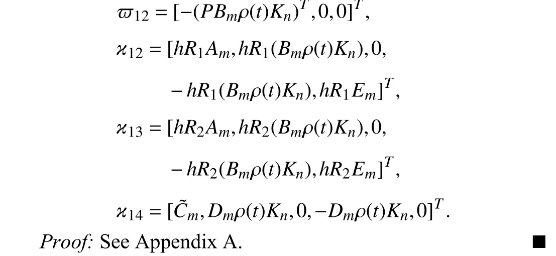
Theorem 1: For given positive scalars, h, γ , κ,ρ(t)∈[ρL,ρU], diagonal matrix σ and control gain matrices Kn, n=1,...,8, the closed-loop system (22) is asymptotically stable under the dynamic threshold parameter (10) and the prescribed H∞disturbance performance level γ if there exist appropriate matrices P>0, Q>0, R1>0, R2>0 and a diagonal matrix Φ >0 such that

B. Co-Design: The Decentralized Case
The following theorem provides the desired communication and control co-design criterion for simultaneously determining the desired control gain matrices Kn, n=1,...,8 and weighting matrix Φ in the decentralized dynamic eventtriggered mechanism (9).


C. Co-Design: The Centralized Case
In this section, we consider that all six state components of the vehicle suspension system (5) are monitored and measured by a single sensor. This case leads to the centralized eventtriggered state feedback control. We next develop two centralized dynamic event-triggered communication mechanisms that regulate the full state transmissions over the invehicle CAN. In particular, the event releasing instants are generated recursively according to the following triggering law

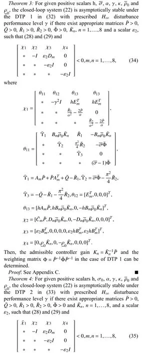
The following theorems provide two co-design criteria for simultaneously determining the control gain matrices Knand the trigger weighting matrix Φ under DTP 1 and DTP 2.

IV. SIMULATION RESULTS
In this section, a quarter vehicle model whose parameters are given in Table I is exploited to show the effectiveness and advantages of the proposed dynamic event-triggered control method under various event-triggered mechanisms and different road disturbances. Specifically, for comparison purposes, we examine the following event triggering mechanisms.

• CDEM1 (centralized dynamic event-triggered mechanism 1): which is based on the proposed centralized dynamic event trigger (31) with DTP 1 in (32). Moreover, we set ϱ=50,σ=0.1and σ=0.2;
• CDEM2 (centralized dynamic event-triggered mechanism 2): which is based on the proposed centralized dynamic event trigger (31) with DTP 2 in (33). Moreover, we choose δ =0.2;
• CSEM (centralized static event-triggered mechanism):which is derived from (31) by setting σ (skh)≡σ=0.1;
• CTTM (centralized time-triggered mechanism): which can be derived from (31) by letting ϱ =0 , σ=0 and σ →0.
In the subsequent simulation cases, the simulation time is set as T =5 sec and the sampling period is chosen as h =1 ms.Then, the total number of the sampled data packets within5 sec is Tm=5000. For better comparative studies between the above triggering mechanisms, we introduce the following transmission rate as a performance metric for the communication efficiency


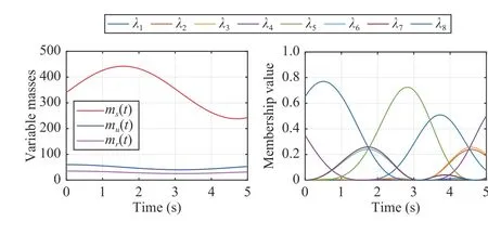
Fig. 4. The variable sprung mass m s(t)∈[238 kg,442 kg], unsprung mass mu(t)∈[40 kg,60 kg] and dynamic mass m r(t)∈[25 kg,35 kg], and the weighting functions λ m(t),m=1,...,8.
A. Bump Responses
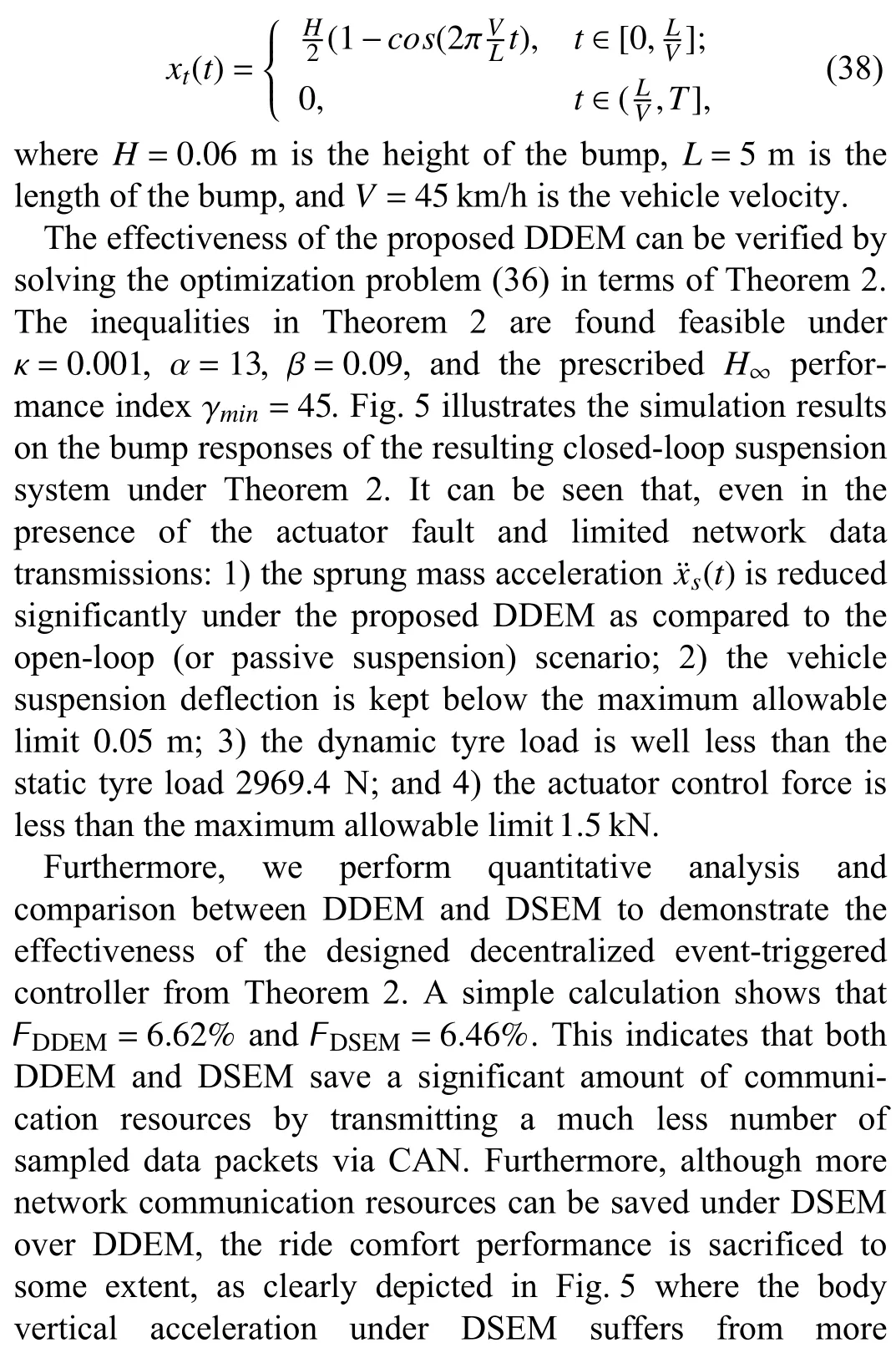
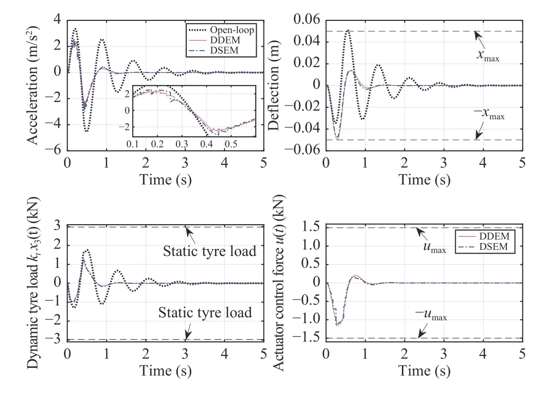
Fig. 5. Bump responses of vehicle body vertical acceleration, suspension deflection, dynamic tyre load and actuator force of open- and closed-loop systems under DDEM and DSEM.
Road inputs can generally be assumed as the discrete events of severe intensity and short span. In this case, an isolated bump input of the following form is considered fluctuations than the DDEM case. For an intuitionistic evaluation of the communication performance of the designed DDEM, the triggering instants and intervals of the individual system state components and the corresponding dynamic threshold parameters are provided in Fig. 6, from which one can see that the data transmissions on sensors are invoked in a dramatically sporadic manner.
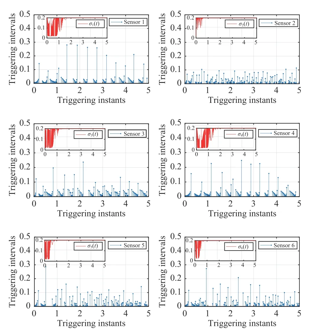
Fig. 6. Triggering instants and intervals as well as the corresponding dynamic threshold parameters σi(sikh) on individual sensors/triggers under DDEM.
B. Comparison Between Different Centralized Event-Triggered Communication Mechanisms
In this case, we evaluate the suspension performance and communication efficiency under different centralized triggering mechanisms. Other parameters are the same as given in the previous section, unless otherwise specified.Solving the optimization problem (36) in terms of Theorem 3 and Theorem 4 under κ=0.01, α=9.8, and γmin=42, it is found that the problem is feasible in both cases. Applying the designed controller to the quarter vehicle suspension system,we obtain the simulation results of each triggering mechanism, as shown in Fig. 7. It can be seen that 1) ride comfort is improved more under the CDEM2 compared with that of CDEM1 and CSEM. The main reason is the CDEM2 permits more sampled data packets to be broadcast over the CAN to maintain better suspension performance; and 2) the other constraint requirements such as suspension deflection,dynamic tyre load and actuator control force are also kept well below the specified limits.
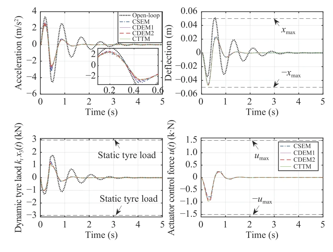
Fig. 7. Bump responses of vehicle body vertical acceleration, suspension deflection, dynamic tyre load and actuator force of open- and closed-loop systems under CDEM1, CDEM2, CSEM and CTTM.
We next perform a quantitative comparison among the event-triggered mechanisms. A simple calculation based on the average transmission rate indicates that CDEM2 transmits 14.40% , CSEM transmits 5 .98% and CDEM1 transmits5.04%of the total sampled data packets. In other words, 85.60%,94.02% and 94.96% of the total sampled data are not transmitted over the CAN under CDEM2, CSEM and CDEM1, respectively. It should be noted that the traditional CTTM transmits all the sampled data (F =100%) over the CAN and thus guarantees the best suspension system control performance than the other triggering mechanisms, as clearly shown in Fig. 7.
C. Random Responses
While running on a real road, a vehicle may subject to unknown and persistent road disturbances. To further evaluate the suspension system performance under the proposed codesign approach, we study the response of the system under different random road disturbances in this case. Specifically, a random road disturbance is deemed as random vibration which can typically be described by a random process [43] as
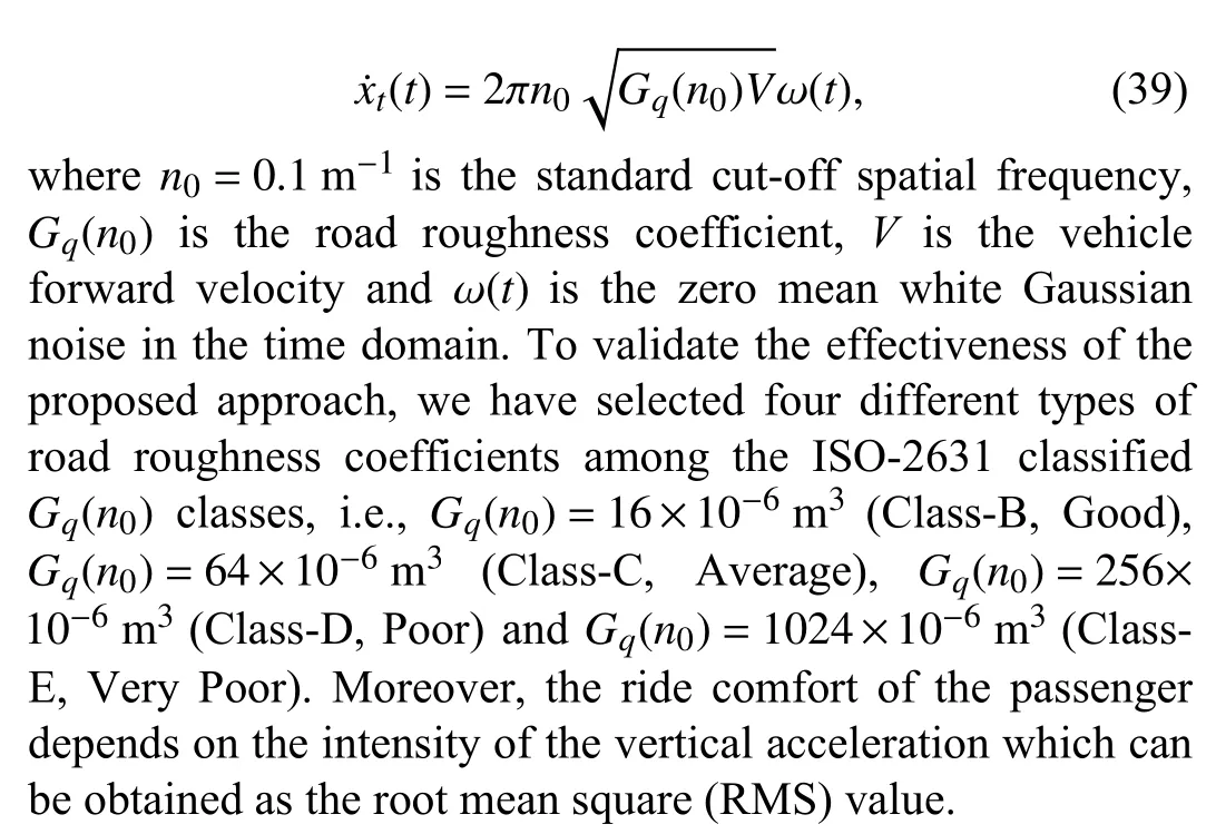
Solving the optimization problem (36) under Theorem 2,Theorem 3 and Theorem 4, and performing the simulation for 5sec under different random road profiles, it can be seen from Fig. 8 that the suspension deflections, dynamic tyre loads and control inputs are all regulated below the maximum allowable limits. Furthermore, the RMS values of vehicle body vertical acceleration, suspension deflection and dynamic tyre load in the decentralized and centralized triggering cases are provided in Table II and Table III, respectively. It can be seen that 1)the vehicle body vertical acceleration is reduced under the proposed DDEM for all road roughness classes. A comparison of RMS value of the vehicle body vertical acceleration shows that an average of 30.2% improvement is noticed under DDEM related to the passive suspension system; and 2) the improvements in the vertical acceleration are more prominent in the case of CDEM1, CDEM2, CSEM and CTTM from Table III. It also reveals that the CDEM2 reduces the acceleration by 27.0% by triggering more data as compared to the CSEM (2 6.7%) and CDEM1 (2 5.7%) but less than the CTTM (2 7.7%) which releases the sampled data packets periodically. This further verifies the effectiveness of the proposed DDEM and CDEMs under ISO-classified random road disturbance. Other performance requirements such as suspension deflection, dynamic tyre load and actuator power limitation can also be easily verified under the concerned random road disturbances, and thus are omitted for brevity.

Fig. 8. Random responses of vehicle body vertical acceleration, suspension deflection, dynamic tyre load and actuator force of open- and closed-loop systems under DDEM, CDEM1, CDEM2 and CSEM.

TABLE II RMS VALUES OF VERTICAL ACCELERATION, SUSPENSION DEFLECTION AND DYNAMIC TYRE LOAD UNDER DECENTRALIzED CASE

TABLE III¨xs(t)m/s2 RMS VALUES OF BODY VERTICAL ACCELERATION ( ) UNDER DIFFERENT RANDOM ROAD DISTURBANCES AND EVENT-TRIGGERED MECHANISMS
Summarizing the above simulation results, it can be concluded that the proposed communication and control codesign approach makes a wise use of the precious communication resources over the CAN, while sacrificing a negligible amount of suspension performance. Furthermore,the proposed DDEM and CDEMs provide a better trade-off between communication efficiency and suspension control performance than the traditional static and periodic counterparts.
D. Frequency Responses
Finally, to further validate the effectiveness of the co-design criteria, the performance of the suspension system is analyzed in the frequency domain. Fig. 9 (a) shows the frequency response of the sprung mass acceleration of the DDEM in comparison to the open-loop (passive suspension) case. The vertical dashed lines represents the lower and the upper bound of the frequency range, i.e., 4–8 Hz in which the human body is sensitive to external vibration. It can be explicitly observed that the sprung mass acceleration is improved to a large extent under the DDEM as compared to the passive system. On the other hand, Fig. 9 (b) presents a comparison among CDEM1,CDEM2 and the open-loop case. The improvement is more pronounced under CDEM2 as compared to the open-loop case. It is obvious from the above simulation results that the sprung mass acceleration is significantly improved under DDEM, CDEM1 and CDEM2 as compared to the passive suspension system in the prescribed frequency region.
V. CONCLUSIONS
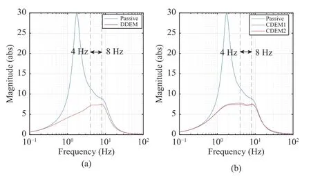
Fig. 9. (a) Frequency response of the sprung mass acceleration of the openand closed-loop systems under DDEM; (b) Frequency response of the sprung mass acceleration under CDEM1 and CDEM2 (m s=238 kg, mu=60 kg,mr =35kg).
The problem of joint dynamic event-triggered communication and active suspension control for an in-wheel-motor driven electric vehicle equipped with advanced-dynamicdamper-motor has been investigated. A T-S fuzzy model for the uncertain system has been derived. To reduce unnecessary data transmissions over the in-vehicle network, a decentralized event-triggered communication mechanism for the individual system state components and two centralized event-triggered communication mechanisms for the overall system state have been developed. The threshold parameters of the event-triggered communication mechanisms can both be regulated dynamically according to the system state variations and performance requirements. Furthermore, a communication scheduling and active suspension control codesign approach has been proposed to guarantee the desired system performance while maintaining satisfactory communication efficiency. Finally, comprehensive simulation studies have been exploited to show the effectiveness and advantages of the derived main results. While the proposed co-design approach shows its promising performance and merits in simulations, there remain a number of issues for future research. For example, this study has been carried out in the entire frequency range under the state feedback control analysis. To obtain better system and suspension performance and render practical applicability, it would be interesting to develop an observer-based dynamic event-triggered controller in a finite/constrained frequency range. Furthermore, as shown in the proof of Theorem 1, the extended Wirtinger inequality [44], [45] has been employed to derive the main results on stability analysis and co-design. To further improve the conservatism of the derived criteria, the existing looped functional approach and its variants [46], [47] in the literature of sampled-data systems could be adopted and further explored.
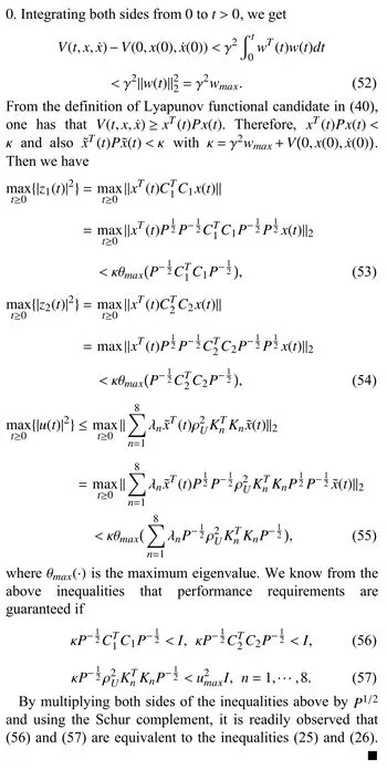
APPENDIX A PROOF OF THEOREM 1


APPENDIX B
The following lemma which is useful for deriving our main result in Theorem 2 is recalled.

PROOF OF THEOREM 2


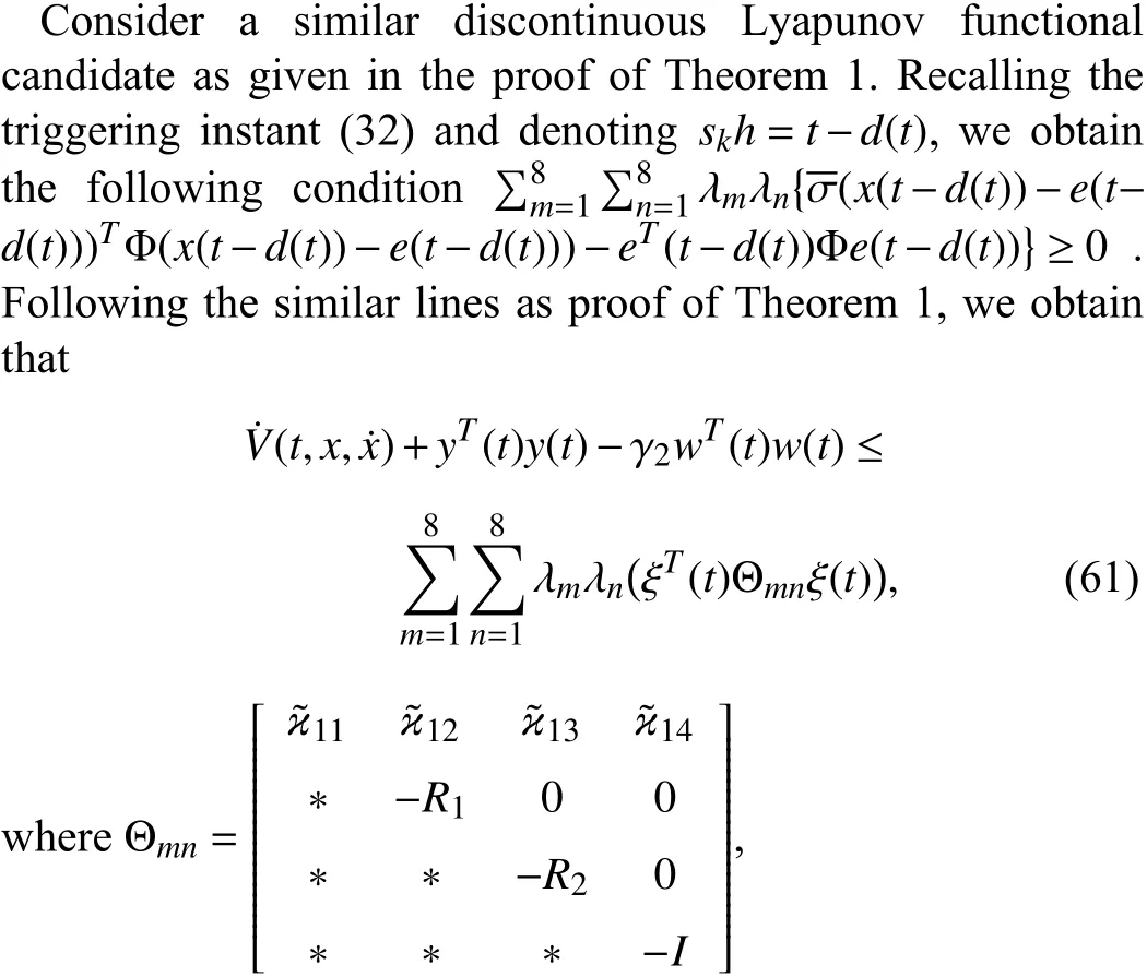
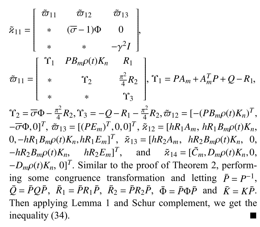
APPENDIX C PROOF OF THEOREM 3
杂志排行
IEEE/CAA Journal of Automatica Sinica的其它文章
- Review of Research and Development of Supernumerary Robotic Limbs
- Control of Non-Deterministic Systems With μ-Calculus Specifications Using Quotienting
- ST-Trader: A Spatial-Temporal Deep Neural Network for Modeling Stock Market Movement
- Total Variation Constrained Non-Negative Matrix Factorization for Medical Image Registration
- Sampled-Data Asynchronous Fuzzy Output Feedback Control for Active Suspension Systems in Restricted Frequency Domain
- Predicting Lung Cancers Using Epidemiological Data: A Generative-Discriminative Framework
