Vibration energy harvesting for low frequency using auto-tuning parametric rolling pendulum under exogenous multi-frequency excitations
2020-12-13SuratPunyakaewManukidParnichkun
Surat Punyakaew*, Manukid Parnichkun
School of Engineering and Technology, Asian Institute of Technology, Thailand
Keywords:Energy harvesting Auto-tuning harvester Parametric rolling pendulum Multi-frequency vibration Low operating frequency
ABSTRACT An electromagnetic parametrically excited rolling pendulum energy harvester with self-tuning mechanisms subject to multi-frequency excitation is proposed and investigated in this paper.The system consists of two uncoupled rolling pendulum. The resonance frequency of each the rolling pendulum can be automatically tuned by adjusting its geometric parameters to access parametric resonance. This harvester can be used to harvest the energy at low frequency. A prototype is developed and evaluated.Its mathematical model is derived. A cam with rolling follower mechanism is employed to generate multi-frequency excitation. An experimental study is conducted to validate the proposed concept. The experimental results are confirmed by the numerical results. The harvester is successfully tuned when the angular velocity of the cam is changed from 1.149 to 1.236 Hz.©2020 The Authors. Published by Elsevier Ltd on behalf of The Chinese Society of Theoretical and Applied Mechanics.This is an open access article under the CC BY-NC-ND license (http://creativecommons.org/licenses/by-nc-nd/4.0/).
The concept of vibration energy harvesting using a planar pendulum excited by vertical motion of its support has attracted considerable attention from several researchers. When the external excitation frequency is equal to twice the resonance frequency of the pendulum, a parametric resonance occurs which makes the amplitude of the pendulum grow exponentially to infinity otherwise be limited by physical constraints. Friction is unable to saturate this growth, which is contrary to the normal resonance caused by a direct periodic external force. Thus, maximum power output is achieved when resonance frequency of the harvesters match one half of the frequencies of external excitation. However, when the external exciting frequency varies, the resonance frequency does not match the exciting frequency, the output power drops significantly. Thus, to maintain the maximum level of output power, an auto-tuning of resonance frequency of the energy harvester is necessary.
The use of parametrically excited pendulum for energy extraction was firstly proposed by Wiercigroch [1]. The proposed energy harvester consists of a pendulum attached to a floating moored device that transforms vertical motion of the floating structure into rotational motion of the pendulum. Najdecka et al.[2] developed a wave energy harvester using parametric pendulum under nondeterministic waves excitation. Xu et al. [3] proposed a numerical and an analytical approach to examine dynamic responses of a parametric pendulum under harmonic excitation. The dynamics of parametrically excited pendulum system have been clarified in Refs. [4–6]. Period-one rotating for a pendulum subjected to combined vertical and horizontal excitation was studied by Pavlovskaia et al. [7]. The rotation stability depends on forcing the parameters and the initial conditions of the pendulum position and velocity, which can be controlled by applying torque to the pendulum was performed in Refs. [8, 9].Reguera et al. [10] employed a control method to maintain rotation of a parametric pendulum. The pendulum was designed to automatically adjust its own length to stabilize unstable periodic orbit. Dotti et al. [11] found that crank/rod ratio and viscous damping had a significant influence on rotational dynamics of a pendulum under reciprocating excitation. Marszal et al. [12]presented a vibration energy harvester based on oscillating pendulum driven by an external excitation with the frequency twice the natural frequency of the pendulum. Kecik [13] presented a magnetic levitation harvester. The maglev harvester device is installed on parametric pendulum. The vibration of magnet in a coil introduces variation in the magnetic flux in the coils and thus generates electricity. Dotti and Sosa [14] presented an energy harvesting system based on the movement of a parametrical pendulum excited by the railroad tracks and sleepers during the passage of a high-speed train. The pendulum is coupled to a generator, which converts the rotational movement of the pendulum, due the vertical oscillations of railroad, in electricity.However, the energy harvesting using rolling pendulum with auto-tuning of resonance frequency has not been reported in the literatures.
This paper presents a vibration energy harvester based on the oscillating rolling pendulum under multi-frequency harmonic excitation. To prove the concept, multi-frequency excitation is required. A cam is designed and manufactured to create multi-frequency excitation. The use of the cam enables the motion of supporting structure of the proposed energy harvester to be muti-frequency excitation. The cam displacement profiley(t)is governed by Fourier series, which can be formulated as follows:

whereAzandnω are the amplitude and frequency of thenth component ofy(t). The multi-frequency excitation occurs whenn>1.The external excitation in this work contains two major frequencies (n=2), with constant amplitudes. This condition represents the common motion of an industrial vibrating machine and a movement of sea wave. The proposed vibration harvester composes of two un-identical rolling pendulums mounted on a supporting structure in order to harvest the vibration energy from these two frequencies. The resonance frequency of the rolling pendulum is controlled by tuning position of the slider on the pendulum arm. The oscillating mechanical energy of the rolling pendulum is converted by electric generator to electrical energy.
According to Eq. (1), if the external excitation hasncomponents,nrolling pendulums are required to harvest the energies from all the components of the external excitation. To reduce the cost and to prove of concept in this paper, the system is designed to harvest the energies of the two highest amplitude frequencies. As the result, two rolling pendulums are mounted on a supporting structure as shown in Fig. 1. Each rolling pendulum is composed of a pendulum arm attached to a shaft of pinion,and a sliding block. The cart is restrained by a spring attached to the supporting structure. The center of mass of each rolling pendulum can be changed by adjusting the position of the sliding blocks. Thus, the resonance frequency of each rolling pendulum can be adjusted by changing the position of the slider to achieve the desired parametric resonance. The swing motion of the pendulum causes the cart oscillates in horizontal plane. This oscillatory motion is converted to electrical energy by an electrical generator through the rack and pinion mechanism.
A mechanical rectifier attached to the generator transforms the oscillatory motion of the rack into unidirectional rotation of the generator by using two one-way bearings in the transmission system.
Figure 1c shows free body diagrams of the rolling pendulum and the cart. The following forces and moments act on the rolling pendulum and the cart: constraint forces:Fi,Ni,Hi,Vi;inertial forces of the generator and the mechanical rectifierspring forceskixi;damping momentsciθ˙iand gravitational forcesmig.
LetQibe center of mass of the rolling pendulum. Distance from center of pinion toQi, defined asis expressed by

wherelgiis distance from center of pinion to the center of mass of pendulum arm,lsiis distance between center of mass of sliding block and center of pinion andmi=mpi+msi.
Because the pinion rolls without slipping, the displacement of the cart, defined asxi, can be expressed by

where θiis angular displacement of the rolling pendulum andriis pinion radius.
Applying the Newton's second law to the rolling pendulum,the followings equations are obtained

Applying the Newton's second law to the cart, the following equation is obtained


Fig. 1.Structure of the proposed vibration energy harvester.1. Generator and mechanical rectifier; 2. Rack; 3. Cart;4. Bearing rod; 5. Sliding block; 6. Pendulum arm; 7. Cam; 8. Supporting structure
whereciis total viscous damping coefficients,I iis moment of inertia of the pendulum arm about center of mass,I r iis moment of inertia of the mechanical rectifier and the electric generator,mc iis mass of cart,k iis stiffness of spring and
Motion of the supporting structure follows a cam profile. The cam profile is designed to generate two harmonic excitation frequencies as expressed by

whereω1=ω,ω2=2ω,ωis angular velocity of the cam,yis vertical displacement of the supporting structure,A1,A2are the amplitudes.
Based on Eqs. (2) to (8) the dynamics equations of the rolling pendulum can be expressed as

The equation of motion of rolling pendulum is nonlinear.However, when the system has small amplitude oscillation and with no base excitation (i.e., s inθi≈θiand c osθi≈1), Eq. (9)can be simplified as

Then, the resonance frequency of the harvester can be expressed as

with

Equation (11) indicates that the resonance frequency can be tuned by adjusting the position of the sliding blocks,l si.
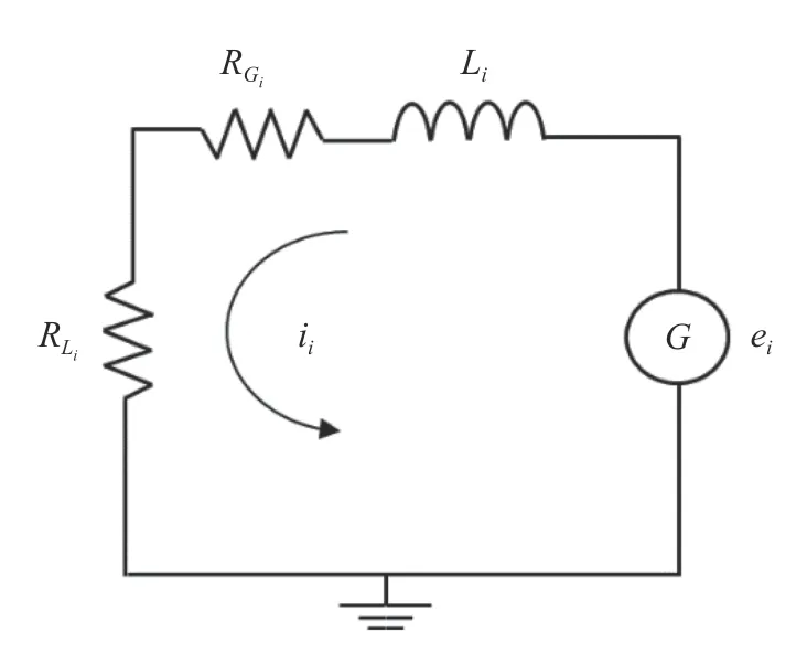
Figure 2 illustrates a direct current (DC) generator model.This model considers the generator as a circuit with three elements connected in series, consisting of a load resistanceRLi, an internal resistance of the electric generatorRG i, an inductanceL i. The output voltage is denoted bye i, and the electric current is denoted byi i.
The output voltagee igenerated by the DC generator is determined from


Fig. 2.Schematic of DC generator electric circuit.
whereke iis generator constant,G iis total gear ratio from pinion to generator.
Apply Kirchhoff voltage law to the circuit,

The instantaneous output electrical powerPigenerated on load with resistanceRL iis determined from

The root mean square (RMS) value of the instantaneous output power is calculated by

whereNis the number of samples andPi jis the value of the sampled instance ofPi.

Fig. 3.a Photo of the rolling pendulums. 1. DC motor; 2. Pendulum arm; 3. Bearing rod; 4. Slider; 5. Weight; 6. Ball screw; 7. Pinion; 8. Shaft support blocks; 9. Pillow block bearing. b Rotary encoder attached at the bottom of the rolling pendulum
Figure 3 shows a photo of the rolling pendulums depicting pendulum arm, ball screw, slider with a weight attached, bearing rod, DC motor and encoder. The pendulum arm is attached to the shaft of pinion by using shaft support blocks. The slider is driven by a DC motor through a ball screw. In this way, the resonance frequency of the rolling pendulum is tuned automatically to track the external excitation frequency.
The schematic diagram of the automatic resonance frequency tuning system is explained in Fig. 4. It is designed to automatically adjust the resonance frequency of pendulum 1 and pendulum 2 to match one half of the frequencies of the first and the second components of the external excitation, respectively. These frequencies are obtained after applying fast Fourier transformation to the vibration measured by an accelerometer.Proportional-integral-derivative (PID) controller is employed to control the position of the slider. The desired positions of sliders are computed using Eq.(11). Figure 5 shows the fast Fourier transform (FFT) of the acceleration signal obtained during the self-tuning experiment. The frequencies of the first and the second components of the external excitation are at the first and the second peak amplitudes, respectively.
The slider positions and the resonance frequencies of both pendulums having the properties listed in Table 1 are determined from Eq. (11) and compared with the experimental measurements as shown in Fig. 6. The experimental and theoretical results are similar, which verify the accuracy of the model.
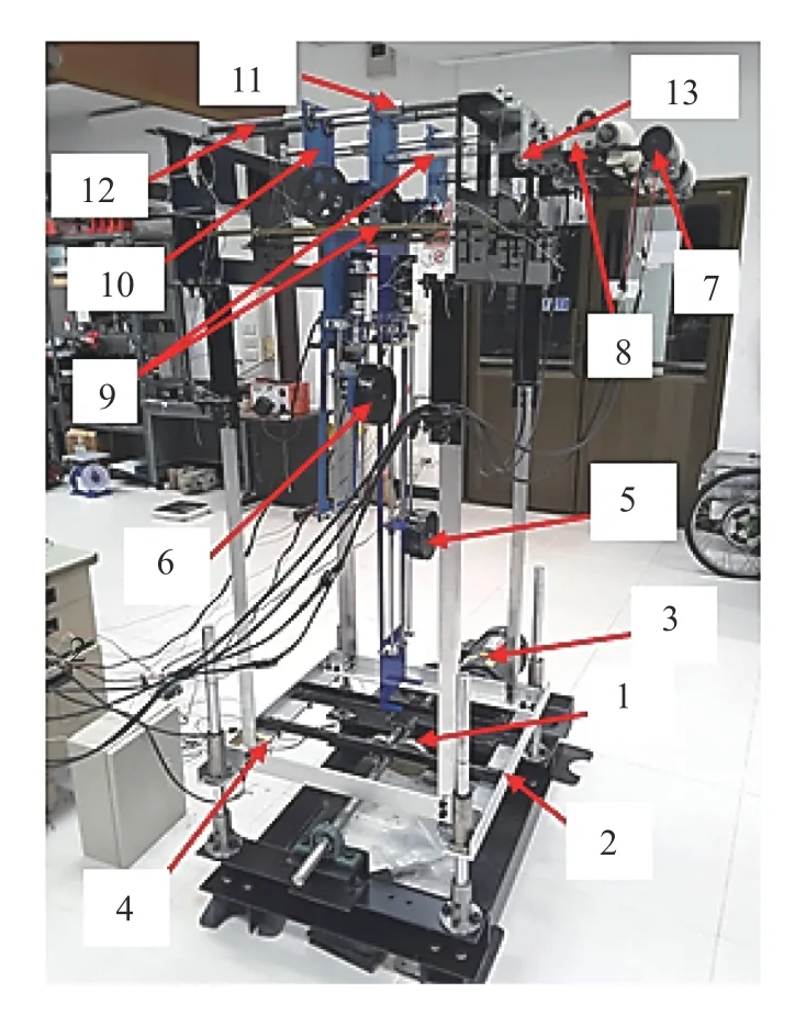
Figure 7 shows the experimental setup of the proposed vibration energy harvester. Each rolling pendulum is connected to the cart by using pillow block bearing. The vertical motion of the supporting structure is generated by the cam with the profile expressed in Eq. (8) which is driven by an electrical geared motor of 1 HP. The angular position and velocity of both pendulums are measured by the encoders connected to the pendulums through rack and pinion mechanisms. Meanwhile the shaker vibration is measured by an accelerometer mounted on the shaker frame. The generator output voltages and the encoder signals are collected by an Arduino due board before sending to a computer.

Fig. 4.Schematic diagram of auto-tuning of resonance frequency

Fig. 5.FFT of the ambient acceleration employed for testing the auto-tuning

Table 1Parameters used in simulation and experiment

Fig. 6.Relationship between resonance frequency of both pendulums and slider positions
Figure 8 shows a photo of the DC generator connected to the mechanical rectifier (MR). There are two one-way bearings installed inside the gears. During operation, the two one-way bearings always work alternatingly: when one is engaged, the other is always disengaged. As a result, the bidirectional vibration of the rack will always drive the shaft of the electrical generator in the same direction.
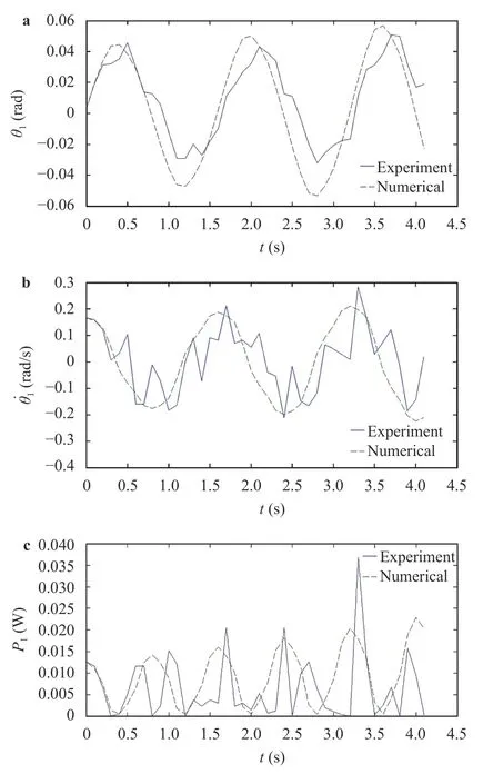
In order to verify the mathematical model, the Eqs. (9), (12),and (13) will be numerically determined by using Runge–Kutta Fehlberg method and compared with the experimental results.The experiments are conducted atωn1=ω1/2=ω/2 andωn2=ω2/2=ωwhere the parametric resonance can be accessed.Figures 9 and 10 show the numerical and experimental results of pendulum 1 and pendulum 2 under multi-frequency vibration.In Figs. 9a, 9b, 10a and 10b, the positions and velocities of the pendulums, measured from the experiments are similar to the values obtained from the numerical results. However, in Figs. 9c and 10c, the instantaneous power from theory analysis and the instantaneous power obtained from the experiment of both pendulums are slightly different because of backlash in the gear system.

Fig. 7.Photo of the experimental set-up. 1. Cam;2. Supporting structure;3.Electric gearmotor;4.Accelerator;5.Pendulum 1;6.Pendulum 2; 7. Electric generator; 8. Mechanical rectifier;9. Racks;10. Cart; 11. Slide bearings; 12. Springs; 13 Rotary encoder

Fig. 8.Photo of mechanical rectifier. 1. One-way bearing; 2. Opposite facing racks; 3. Pinion; 4. Right shaft; 5. Left shaft; 6. Output shaft;7.Gear; 8. Electric generator

Fig. 9.Comparisons between the experiment and analytical results of pendulum 1:a angular position of pendulum 1, b angular velocity of pendulum 1, c instantaneous power of pendulum 1
The power output of pendulum 1from the theoretical prediction was found to be 0.011WR M S, and the equivalent experimental power output was 0.01WR M S. Meanwhile the power output of pendulum 2 from the theoretical analysis was 0.1672WR M S, and the experimental analysis had a power output of 0.1466W R M S. To attain higher efficiency of energy harvest it is necessary to apply high performance electric generator with low mechanical damping. The results corresponds toωn1=3.92 rad/s,ωn2=7.97 rad/sandω=7.82 rad/s. The initial positions and velocities of the pendulums have the following values:Values of the other parameters are listed in Table 1.
Auto-tuning of resonance frequency of the harvester is tested by varying the external excitation frequency.

Fig. 10.Comparisons between the experiment and analytical results of pendulum 2: a angular position of pendulum 2, b angular velocity of pendulum 2,c instantaneous power of pendulum 2
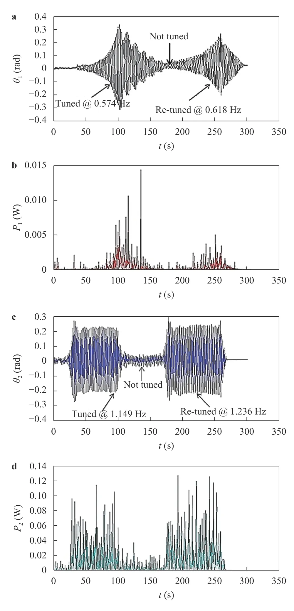
Figure 11 shows the harvester angular position and instantaneous power of both pendulums when angular velocity of the cam is changed from 1.149 to 1.236 Hz. It is shown that if angular velocity of the cam is abruptly changed to 1.236 Hz during operation, the drops in the angular positions and instantaneous powers occurs because of the mistuning. This event only occurs for a certain period of time, until the sliding block of both pendulums is automatically re-tuned to the new positions where the parametric resonance occurs again. The average instantaneous output power in RMS of pendulum 1 and pendulum 2 are 1 mW and 23.2 mW, respectively. It can be observed that pendulum 2 swings faster than pendulum 1. Furthermore, pendulum 1 requires longer time period of the parametric transient build-up than pendulum 2.

Fig. 11.Resonance frequency tuning, angular velocity of the cam change from 1.149 to 1.236 Hz: a angular position of pendulum 1, b instantaneous power of pendulum 1, c angular position of pendulum 2, d instantaneous power of pendulum 2.
This paper presented an auto-tuning energy harvester for low frequency using parametric rolling pendulum under multifrequency excitation. The system consists of two rolling pendulums and sliding blocks. The resonance frequency of each pendulum is tuned by adjusting the position of the sliding block. A mathematical model was derived and verified by the experiments. The results obtained from the numerical were closely similar to the experimental results. The resonance frequency of both pendulums were automatically tuned when angular velocity of the cam was changed from 1.149 to 1.236 Hz by adjusting the position of the sliders. The proposed energy harvester is effective for multi-frequency excitation environment, and hence is applicable for multi-component excitation. The maximum swing angle of the proposed rolling pendulum is limited by its construction. All types of rolling pendulums possess this limitation.Additionally, the activation of parametric resonance requires longer transient build up time than normal resonance.
杂志排行
Theoretical & Applied Mechanics Letters的其它文章
- A modified Lin equation for the energy balance in isotropic turbulence W.D. McComb*
- Influence of wing flexibility on the aerodynamic performance of a tethered flapping bumblebee
- Efficient model for the elastic load of film-substrate system involving imperfect interface effects
- Interactions of human islet amyloid polypeptide with lipid structure of different curvatures
- Evolution of vortices in the wake of an ARJ21 airplane: Application of the liftdrag model
- Analytical and numerical studies for Seiches in a closed basin with bottom friction
