Micromechanical analysis on tensile properties prediction of discontinuous randomized zalacca fibre/high-density polyethylene composites under critical fibre length
2020-03-27DodyAriawanEkoSurojoJokoTriyonoIbrahimFadliPurbayantoAgilFitriPamungkasAdityaRioPrabowo
Dody Ariawan*, Eko Surojo, Joko Triyono, Ibrahim Fadli Purbayanto, Agil Fitri Pamungkas,Aditya Rio Prabowo*
Department of Mechanical Engineering, Universitas Sebelas Maret, Surakarta 57126, Indonesia
Keywords:Zalacca fibre Micromechanical analysis High-density polyethylene Critical fibre length Tensile properties
ABSTRACT In this research, the tensile properties' performance of compression moulded discontinuous randomized zalacca fibre/high-density polyethylene under critical fibre length was analysed by means of experimental method and micromechanical models. These investigations were used to verify the tensile properties models toward the effect of fibre length and volume fraction on the composites. The experimental results showed that the tensile properties of composites had significantly increased due to the enhancement of fibre length. On the contrary, a decline in the tensile properties was observed with the increase of volume fraction. A comparison was made between the available experimental results and the performances of Tsai-Pagano, Christensen and Cox-Krechel models in their prediction of composites elastic modulus. The results showed that the consideration of fibre's elastic anisotropy in the Cox-Krenchel model had yielded a good prediction of the composites modulus, nevertheless the models could not accurately predict the composites modulus for fibre length study.
1 Intr oduction
Over the past few decades, there has been a growing interest in the use of natural fibres in composite applications with future potential to replace isotropic materials, such as steel in building and marine structures [1-5]. These types of composites present various advantages, such as high specific strength and modulus,low cost, low density, renewable nature, biodegradability, absence of associated health hazards, easy fibre surface modification, wide availability and its relative non- abrasiveness [6]. Natural fibres come in a variety of forms and the random discontinuous fibre form has been used in various researches and applications due to its great potential as a composite reinforcement [7-9]. Zalacca is a local name for snake fruit and belongs to the Arecaceae family. The zalacca fibre (ZF) is a type of natural fibre that is extracted from Salacca zalacca midrib and is composed by 44.87% alfacellulose, 35.84% hemicellulose, 21.96%lignin, 14% water content, 115.43 MPa tensile strength and 1%-2.25% elongation [10, 11]. Raharjo et al. [10] reported that an opportunity to combine the zalacca midrib fibre with thermoplastic polymer is exist, such as low density polyethylene(LDPE), as a reinforcement in the production of composites.
High-density polyethylene (HDPE) is one of the most widely used thermoplastic polymers in the household and industrial applications. Previous studies [6, 12] have used the HDPE matrix on composites with natural fibres such as cantala, kenaf and sisal fibres using several fabrication methods, i.e. compression moulding, injection moulding etc. Raharjo et al. [12] found that there was good interaction between HDPE and natural fibres in composite, which was fabricated by using compression moulding. Compression moulding is the most popular fabrication method for thermoplastic polymer, which is a high-volume,high-pressure method and suitable for moulding complex as well as high-strength reinforcements [12, 13].
Tensile properties are an essential factor that expresses the mechanical properties of materials. In general, the tensile properties of fibre reinforced polymer composites are affected by several factors, such as fibre volume fraction, fibre matrix interaction, fibre aspect ratio (diameter to length of fibre), fibre orientation and fibre bridging mechanism [8, 14]. Owing to its complex structure, the random discontinuous fibres had been effectively used to ease fabrication of natural fibre composites. The effectiveness of charge transfer from the matrix to the fibre mainly depends on the fibre length (lf). Numbers of researchers had discovered that long fibre produces higher flexural and impact strengths as compared to short fibres [15-17]. The length of discontinuous fibre could be categorized into three types, namely under critical length, above critical length and beyond the critical length. Critical length (lc) is the minimum fibre length that could effectively transfer the load from matrix to the fibre. Fibres that go beyond the critical length is capable to carry an increasing fraction of the applied load, and may experience fracture before the matrix. As such, for continuous fibre that goes beyond the critical length (lf≫lc), the tensile properties were derived from equations in tensile properties models [18]. Although fibres shorter than the critical length will not be able to effectively support the loading transfer to the matrix, they could be injected uniformly and optimally fill the mould cavity.
To reduce cost on time-consuming experiments, prediction of tensile properties is possibly carried out using the mechanics of composite models methods and numerical methods [19].Generally, several elastic constants of composite may be accurately tested by experimental measurement, but this research method is usually expensive and time consuming. The importance of predictions in the fibre composites' strength and elastic modulus under critical length has led to many micromechanical studies being conducted, particularly on the random discontinuous natural fibre-HDPE composites. Nevertheless, the comparison study of experimental and prediction model on the random discontinuous composites under critical length are limited, especially on natural fibre reinforcement over a range of fibre volume fractions (Vf) and fibre lengths (lf). This research focused on several models to produce the accurate calculation on the tensile properties of composites [8, 19, 20]. The Tsai-Pagano,Christensen and Cox-Krenchel models had been used to predict the elastic constants, while the predictions of tensile strength were carried out by using Hirsch and Bowyer-Bader models [8].
2 Experiments
2.1 Material
The preparation of zalacca fibre mats was done according to the sequence of being water retted for 14 days in distilled water,dried in an oven machine at 60 °C for 24 hours and subsequently underwent the cutting, mixing and pressing processes. This had produced zalacca fibre with an average density of 1.28 g/cm3.For the study of volume fraction variation, the length of fibre was prepared at 3 mm, while for the study of fibre length; they had been varied from 1 mm, 3 mm, 6 mm and 9 mm. All ZF length types of random oriented mat had been prepared by the pressing method. The HDPE used in this research was grounded to produce mesh 20-40 with a density of 0.9 g/cm3. The neat resin of HDPE following the fabrication has a flexural strength of 20.89 MPa, an elastic modulus of 0.65 GPa and an izod impact of 20 kJ/m2.
2.2 Composites fabrication
The fibre loading of composites for analysis of volume fraction (Vf) variation was arranged at 0, 0.1, 0.2, 0.3 and 0.4, while for the study of fibre length, the fibre loading of composites was prepared at 0.3Vf. The zalacca midrib fibres/HDPE composites were produced using compression moulding with pressing temperature at 150 °C, pressing pressure at 50 bar (1 bar=1×10⁵Pa)and holding time of 25 minutes. Additionally, the 90° of fibre orientated composites samples with 0.3Vfhad also been prepared to determine the transverse tensile fibre properties (Ef2, σf2)through the use of rule of mixture model for transverse loading.
2.3 Mechanical testing
The evaluation of fibre tensile strength (σf1) and the longitudinal elastic modulus, Ef1of ZF was conducted based on ASTM C1557 standard by using the miniature tensile tester model Tenso Lab 3 Mesdan with a load cell of 30 kg. Twenty single ZF samples were used for measuring the longitudinal tensile properties of ZF. The interfacial shear strength (IFSS) of the ZF-HDPE was studied by a single-fibre pull-out test [12]. The sample was prepared by placing the ZF in HDPE film on an aluminium mould using a hot press. The gauge length was set at 10 mm and a hole was drilled to embed the fibre length in the matrix. The IFSS test was carried out on an universal testing machine JTMUTS510 with a crosshead speed of 0.10 mm/min.
The tensile properties of the ZF/HDPE composites and neat resin samples were tested according to the ASTM D638 standard using universal testing machine JTM-UTS510. The test machine was also equipped with a 5 kN load cell at a 5 mm/min rate. The tensile testing is consist of three types of fibre orientation, i.e.longitudinal fibre to determine 0° and 90° fibre orientation composite properties, and random discontinuous fibre to modelling analyses. The deviation between experimental results and prediction results are calculated using Eqs. (1) and (2). The first expression was used to calculate the deviation of elastic modulus,while the second expression was used to calculate the deviation of tensile strength of composites

where eElasis the elastic modulus deviation, eTensis the tensile strength deviation, Epredis the elastic modulus of prediction result, Eexpis the elastic modulus of the experimental result, σpredis the tensile strength of the prediction result and σexpis the tensile strength of the experimental results.
2.4 Physical testing
The fractured composite surface on the cross-section of zalacca midrib fibre composite was observed by using scanning electron microscope (SEM) model JSM-6701F JEOL. A plasma sputtering apparatus that operated at a pressure of 2 mbar was used to coat all specimen surfaces with platinum for a duration of 3 minutes prior to SEM observation.
The measurements of fibre and matrix density were conducted in accordance with ASTM D3800 by using ten measurements for each type of samples. The solution used had been alcohol with a density of 0.7893 g/cm3.
3 Results and discussion
3.1 Properties of single zalacca fibre
Table 1 summarizes the physical and tensile properties of the single ZF that had been extracted from zalacca midrib via water retting process. The longitudinal tensile properties of ZF had been within the range of results obtained from past studies conducted on a similar fibre [10, 11].
Table 2 shows the tensile properties and density of HDPE,which are lower than the ZF. This data indicates that the ZF had entirely supported the composites as reinforcement, and the modelling method used in the composites calculation for fibre elongation had been lower than the matrix elongation (εf1<εm)[18]. Table 2 displays the IFSS and the critical length (Lc) of ZF/HDPE. The critical length had been calculated [18]

where d is the fibre's diameter,is the longitudinal tensile strength of fibre and τyis the IFSS. These results were used to determine the fibre length variation for further modelling discussion. Table 2 shows that Lcof ZF fibre to HDPE is quite long as reinforcement of composites. This phenomenon could emerge due to the presence of fibre impurities that are still attached to the ZF surface (see Fig. 1). The impurities and cemented wax would impede the interaction or interfacial bonding between the natural fibre and the matrix [21].
The transverse strength properties of ZF can be determined by calculating the tensile result of 90° fibre orientation composites as shown in Table 3. A semi-empirical model developed by Tsai and Hahn was used to find the prediction of transverse elastic modulus (Ef2), while the transverse tensile strength of the composite (σ2) was taken for the transverse strength of ZF (σf2).The predicted Ef2value was 107.9 MPa, while Ef1had a significant lower value of 4.03 GPa. This value indicates that the single ZF had been highly anisotropic because of the remarkable difference between Ef2and Ef1[8]. The transverse tensile strength (σf2)of ZF was established since the σ2had been lower than the matrix tensile strength (σm) (see Table 2), which indicates that the first ply failure transverse mode had occurred due to the failure of ZF [18]. Therefore, the fibre transverse strength (σf2) is estimated to be similar to the composites transverse strength (σc2) in the next modelling calculation.

3.2 Effect of fibre loading on tensile properties
Table 4 shows the experimental variation results of the tensile properties in composites reinforced by 3 mm fibre length at different fibre volume fractions. The addition of ZF under critical length had exhibited lower strength than that of HDPE matrix, while the increment of fibre loading had reduced the elastic strength of ZF composites. The tensile strength had reduced by 15.6% with the addition of 0.1Vfof nonwoven mats. A further addition of ZF loading by 0.2Vf, 0.3Vf, and 0.4Vfhad reduced the tensile strength by 25.2%, 37.1%, and 49.3% respectively.
The elastic modulus had shown a reduction of 38.3% upon the incorporation of 0.1Vf. At 3 mm fibre length, the existence of fibre had not been adequate in providing the required high modulus to the HDPE matrix. The increase in the Vfhas led to a decline in the ZF modulus, which had been similar to the decreased tensile strength of the composite. In this research, the lowest elastic modulus was attained at 0.4Vfwith 49.1% degradation from the elastic modulus of neat HDPE. The weakening of tensile properties could be associated with under critical length.Critical length is the minimum fibre length that could effectively transmit fibre loading to the matrix by interfacial bonding. A low interaction of bonding between the fibre-matrix would onlyprovide minimum reinforcement to composites and results in the reduction of tensile properties [13].

Table 1 Physical and tensile properties of single ZF.

Table 2 Tensile properties of HDPE, density of HDPE, IFSS, and critical length (Lc) for ZF/HDPE
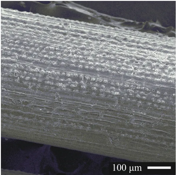
Fig. 1. Zalacca fibre surface
Table 4 shows the void content of the ZF composites at different Vfvalues, where all the results were less than 5%. The void contents denote an enhancing tendency on Vf. The highest void content was 4.27% at 0.4Vf. Void formation in composites could be caused by several reasons, such as the inability of the matrix in displacing air from the fibre surface, incomplete wetting between the fibre and the matrix or the presence of micropores in the natural fibre [21-23].
3.3 Effect of fibre loading on tensile strength
Several micromechanical models have been proposed and established to calculate the tensile properties of fibrous polymer composites. The established micromechanical models were useful in predicting and validating the tensile experimental results.This research deployed the two-dimensional mode for all modelling calculations since the fibre lengths had been longer than the composite thickness [18].
The Bowyer-Bader and Hirsch models were selected to predict the tensile strength of ZF composites at several fibre volume fractions (Vf). These two pertinent models have been used widely in previous studies, and had produced reliable predictions [8, 24]. These models are based on a combination of parallel land series model (rule of mixture). According to the Bowyer Bader model, the tensile strength of the composite (σC) can be derived as follows

where σfis the fibre tensile strength, σmis the tensile stress in the matrix at fibre failure strain, Vmis the matrix volume fraction, K1is the orientation of fibre and K2is the factor of fibre length factor. In the case of fibre length that is greater than the critical length (lf> lc), K2is calculated as follows

while for fibre length that is shorter than the critical length (lf<lc), K2can be derived from the following equation

Based on previous studies [25], the orientation factor K1was assumed to be 0.2. As presented in Table 3, the estimated critical length of ZF that was obtained by using the IFSS of ZF toward HDPE is 10.6 mm. The length of the ZF used in the study of volume fraction was 3 mm shorter than its critical fibre length(10.63 mm). Therefore, by using Eq. (3), K2had been determined as 0.28.
The second model used is based upon an existing version of the law of mixtures, called the Hirsch model [26], which combines the series and parallel elements of phases. According to the model, the tensile strength of the composite can be calculated as

where based on an agreement between experimental and theoretical values, x is 0.1 for randomly oriented fibre composites [9].
As shown in Fig. 2, the Hirsch model had overvalued the tensile strength of the ZF composites at each Vfvalues. The results derived from the Hirsch model had significantly deviated by 32.7%, 91.7%, 127.1%, and 245.8% at each of its corresponding Vfvalue (see Table 5). This model had produced a different trend of tensile strength to the experimental results, thus was proven to be unsuccessful in representing the tensile strength prediction of composites under critical length.
The Bowyer-Bader's model prediction values had produceda similar trend with the experimental results, where the tensile strength deviations at various Vfhad a range between 9.4% and 36.8%. Figure 2(a) shows the decrease of tensile strength along with volume fraction enhancement. The closer proximity of prediction results could be attributed to the introduction of fibre orientation and length factors in the Bowyer-Bader equation,which had been absent in the Hirsch model (refer to Table 5).The deviation of Bowyer-Bader's model had increased at a higher Vfvalue. This could be due to the interfacial interaction that was not calculated in the Bowyer-Bader model. At a high Vfvalue, the stress concentration point would occur at fibre-rich area, which has poor fibre-matrix interaction. A poor interaction between the matrix and fibre would consequently reduce the tensile strength of the composites.

Table 3 Transverse strength properties of composites

Table 4 Tensile properties and composites void content in different volume fraction
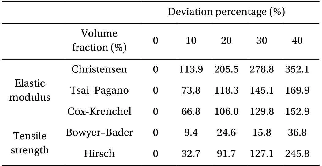
Table 5 Deviation percentage of elastic modulus and tensile strength between experimental results to prediction results accounting for volume fraction variation
3.4 Effect of fibre loading on modulus prediction
The in-plane modulus of a random fibre composite as proposed by Halpin-Tsai and Pagano [18] can be used to estimate the modulus of the random fibre composite that uses the same fibre/resin

where E11is the elastic modulus of the longitudinal direction loading and E22is the elastic modulus of the transverse direction loading.
Similar with the previous model, the elastic modulus model as proposed by Halpin-Tsai was used to determine both E11and E22, where the modulus of elasticity, the volume fraction of the composite component as well as the ratio of the geometric dimensions of the fibre were taken into consideration [22, 23]
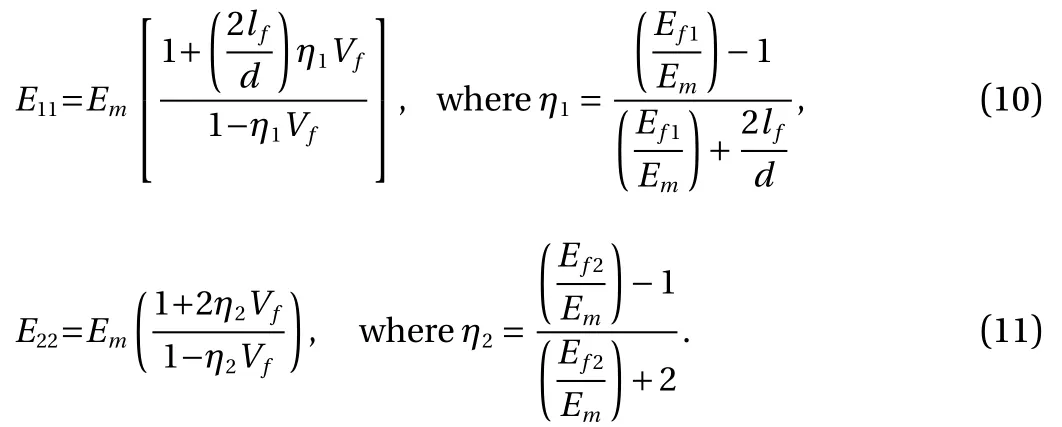
Ef1, Ef2and Emrepresent the corresponding longitudinal modulus of the fibre, the transverse modulus of the fibre and the elastic modulus of matrix. lfis the fibre length, while d is the average diameter of fibres.
The second model used to predict the modulus is the Cox-Krenchel. This model had produced decent prediction for elastic modulus, whereby the calculation was incorporated the dimension and orientation factors of the fibre phase [27-31]. According to Cox-Krenchel model, the elastic modulus, EC, can be derived from the following [20, 27]

where ηlis the fibre length distribution factor and ηois the fibre orientation distribution factor. The fibre orientation factor was calculated based on Krenchel's theory [8]

where αois the fibre orientation limit angle and for in-plane random fibre orientation laminates, the orientation factor (ηo) is 0.375 [30]. Subsequently, ηlis determined based on the Cox shear lag theory as shown [32]


where β is the shear-parameter, denotes the stress concentration rate coefficient at fibre's end, lfis the length of fibre and vmis the Poisson's ratio of matrix. Since fibres are arranged laterally in a square packing configuration, the value of xiis taken as 4.
Christensen had examined the behaviour of a composite system with a two-dimensional random fibre orientation. This model had considered the effect of fibre orientation and fibrematrix interaction, which can be simplified as below [33]

where Vfis the volume fraction of fibre, Emis the matrix modulus, Efis the fibre modulus and Ecis the composite modulus.
Figure 2(b) shows the results of predicted and experimental elastic modulus of ZF composites at all Vf. The results of modulus tensile predictions by all three models diplayed a linear increment as a function of Vf, which was different compared to the experimental results. The model by Christensen had a significant over estimation to the modulus of tensile at all Vfvalues,where the elastic modulus deviations for 0.1Vf, 0.2Vf, 0.3Vf, and 0.4Vfwere 113.9%, 205.5%, 278.8%, and 352.1%, respectively (see Table 5). This model had produced the highest deviation as compared to the Tsai-Pagano and Cox-Krenchel models.
The deviations derived from the Cox-Krenchel and Tsai-Pagano models are still significant although both models had not been able predict the elastic modulus of ZF-HDPE composites under critical length. For the Tsai-Pagano model, the prediction had deviated 73.8% from the experimental result at 0.1Vf. The corresponding deviations at 0.2Vf, 0.3Vf, and 0.4Vf, were 118.3%,145.1%, and 169.9% above the experimental values, while Cox-Krenchel's model had lower deviations as compared to the other models (refer to Table 5). This results occurred due to the inclusion of fibre length and fibre orientation factors in the calculation. Nevertheless, all of these models could not accurately predict the tendency of elastic modulus, which could be attributed to the exclusion of critical length and interfacial strength factors in the equations, as demonstrated by the Bowyer-Bader equation for tensile strength prediction.
As a natural fibre, ZF has large properties variations as a result of its varied cellulose content and fibres dimensions. Furthermore, in the previous part of this paper, ZF had been verified to be elastically anisotropic (refer to the different values of Ef1and Ef2). These could affect the capability of the models in producing accurate elastic modulus predictions. Facca et al. [34] had implied that the inclusion of fibre angles and length distribution corrections could probably improve the results derived from prediction models. Previous studies [7, 35] had stated that fibre elastic modulus was influenced by the content of cellulose in the fibre and the spiral angles of crystalline fibrils in the cellulose.Furthermore, the existence of void as shown in Table 4 would also have an effect on the prediction results.
3.5 Effect of fibre length on tensile strength
Figure 3(a) shows the correlation between the predictions and experimental results. The experimental results had indicated 39.3% of tensile strength improvement along with the increase of fibre length. The highest strength was obtained by the 9 mm of fibre length with a tensile strength of 16.33 MPa, while the lowest strength of 11.72 MPa had occurred at 1 mm of fibre length. The increase in tensile strength could be attributed to the improvement of fibre length that had contributed to the fibre load bearing efficiency; however the tensile strength improvement were still lower than the strength of the matrix. This could be related to the fibre length that is shorter than the fibre's critical length. Previous studies have reported that the contact area of a longer fibre to matrix was influenced by the enhancement of interaction bonding or interfacial strength that affects the fibre's capability in transferring the load to the matrix [16, 36].
Based on the obtained results in the volume fraction effect,the Bowyer-Bader model had provided closer proximity to the experimental results than the Hirsch model. The Bowyer-Bader model results resulted a tensile strength deviation of 11.8%,15.8%, 9.5%, 4.3%, and 1.1% at 1 mm, 3 mm, 5 mm, 7 mm, and 9 mm of fibre length respectively (see Table 6). Furthermore, the results from this model had shown a similar trend with the experimental results, where there was an increment of tensile strength along with the increase of fibre length. Athijayamani et al. [37] stated that the deviation in the Bowyer-Bader could be attributed to the absence of the void content factor in the equation (which had existed in the ZF composites as shown in Table 3).
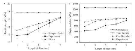
Fig. 3. Experimental and predicted a tensile strength and b elastic moduli of ZF-HDPE composites at different fibre length
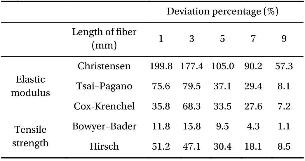
Table 6 Deviation percentage of elastic modulus and tensile strength between experimental results to prediction results related to the length of fiber variation
The results obtained from the Hirsch model had a higher tensile strength deviation as compared to Bowyer-Bader. This model had not been able to show the effect of fibre length on the tensile strength of ZF composites. The calculation had deviated 51.2%, 47.1%, 30.4%, 18.1%, and 8.5% at 1 mm, 3 mm, 5 mm, 7 mm, and 9 mm of fibre lengths, respectively (refer to Table 6).The Hirsch model had assumed the composite to have good interfacial interaction, void-free, as well as possessing linear elastic properties and a homogenous distribution of fibre in the composites. However, the fibre length and the interfacial strength of composites constituents had been omitted from the Hirsch equation. The mentioned factors might have contributed to the high deviation between the Hirsch model and the experimental results.
3.6 Effect of fibre length on elastic modulus
Similar to the results of composites elastic moduli, the tensile strengths of composites have a tendency to increase along with the enhancement of fibre length (refer to Fig. 3(a)). The predictions from Christensen, Tsai-Pagano, and Cox-Krenchel had been considerably higher than the experimental results. The elastic modulus of both Tsai-Pagano and Cox-Krenchel models and the experimental results had increased with the enhancement of fibre length, while the results obtained from Christensen model had exhibited similar values but at different fibre lengths.The prediction equations were taken from previous discussions.The utilization of 9 mm fibre length in composite had a 422 MPa of elastic modulus or 90.5% higher than the 1 mm fibre length composites. This improvement could be triggered by the increase of tensile strength or the increase of the fibre's ability in transferring the load to the matrix that had been discussed earlier.
Figure 3(b) depicts the prediction of elastic moduli by using the Cox-Krenchel and Tsai-Pagano models. The predictions by Tsai-Pagano had been considerably higher than the experimental results, while the results derived from the Cox-Krenchel model had demonstrated the lowest deviation from the experimental results. The results of elastic modulus could be arranged as follows: Christensen > Tsai-Pagano > Cox-Krenchel > Experimental results. The deviation of modelling results (see Table 6) could be due to several factors, such as the uniformity of fibre distribution and strength of fibre, the complex geometric of ZF, voids,punching direction, interlocking of fibre in mat and interfacial adhesion.
3.7 Effect of fibre length on fracture surface observation
Figure 4 illustrates the morphology of the fracture surface of composite fracture with fibre length of 1 mm, and a composite fracture with a fibre length of 9 mm.
Figure 4(a) shows that pull outs and hole modes had been the main contributing factors for composite failures. These factors indicate the low interfacial bonding between the fibre and the matrix due to the inefficiency of load transfer. The weak interaction of the fibre-matrix had caused the composite to fail before the optimum strength is achieved. Furthermore, the existence of gap or void had also degraded the strength of the composite bonds [16]. Figure 4(b) shows the fracture fibres and narrow gap surface of fracture composites. These phenomena imply that longer ZF would be able to offer more support to the composites in tensile loading than shorter ZF as shown in Fig.4(a). Therefore, longer fibre has the ability to optimally transfer the load of tensile stress to the matrix as a result of better interfacial shear strength between the ZF and HDPE.
4 Conclusions
Several conclusions could be drawn from the study of discontinuous randomized zalacca fibre/high-density polyethylene composites under critical length. To begin with, the enhancement of fibre length had increased the tensile properties of ZF composites. On the contrary, the addition of fibre loading under critical length ZF to HDPE matrix had resulted in the decrease of both elastic modulus and tensile strength, although the highest tensile properties were attained at 0.1Vf. The Bowyer-Bader model that was used for the calculation of tensile strength in different fibre loading and different fibre length had provided good prediction on ZF composites under critical length, while Hirsch model had a high tensile strength deviation from the experimental results. Although the utilization of models to determine the elastic modulus could not provide decent predictions for ZF composites under critical length with different fibre loading,among of all the various theoretical models, the Bowyer-Bader model provided the best predictions, considering the introduction of fibre parameter and fibre length parameters in the equation.
Acknowledgements
The authors would like to acknowledge the financial support given by Universitas Sebelas Maret by providing PNBP (Grant 543/UN27.21/PP/2018).
杂志排行
Theoretical & Applied Mechanics Letters的其它文章
- On the plastic buckling of curved carbon nanotubes
- Neurodynamics analysis of cochlear hair cell activity
- Prolonged simulation of near-free surface underwater explosion based on Eulerian finite element method
- Minimizing electrostatic interactions from piezoresponse force microscopy via capacitive excitation
- Spatial artificial neural network model for subgrid-scale stress and heat flux of compressible turbulence
- An analytical model to predict diffusion induced intermetallic compounds growth in Cu-Sn-Cu sandwich structures
