Distributed active fault tolerant control design against actuator faults for multiple mobile robots
2019-12-09MahmoudHUSSEINJawharGHOMMAMAzeddineGHODBANEMaaroufSAADVahNERGUIZIAN
Mahmoud HUSSEIN, Jawhar GHOMMAM, Azeddine GHODBANE, Maarouf SAAD, Vah’e NERGUIZIAN
1.Department of Electrical Engineering, ´Ecole de Technologie Sup´erieure,1100,rue Notre-Dame Ouest,Montr´eal,Qu´ebec,H3C 1K3,Canada;
2.Department of Electrical and Computer Engineering,Sultan Qaboos University,P.O.Box 31,Al-Khoud 123,Sultanate of Oman
Abstract This paper investigates the active fault tolerant cooperative control problem for a team of wheeled mobile robots whose actuators are subjected to partial or severe faults during the team mission. The cooperative robots network only requires the interaction between local neighbors over the undirected graph and does not assume the existence of leaders in the network.We assume that the communication exists all the time during the mission.To avoid the system’s deterioration in the event of a fault,a set of extended Kalman filters(EKFs)are employed to monitor the actuators’behavior for each robot.Then,based on the online information given by the EKFs,a reconfigurable sliding mode control is proposed to take an appropriate action to accommodate that fault. In this research study, two types of faults are considered. The first type is a partial actuator fault in which the faulty actuator responds to a partial of its control input, but still has the capability to continue the mission when the control law is reconfigured. In addition, the controllers of the remaining healthy robots are reconfigured simultaneously to move within the same capability of the faulty one. The second type is a severe actuator fault in which the faulty actuator is subjected to a large loss of its control input, and that lead the exclusion of that faulty robot from the team formation. Consequently, the remaining healthy robots update their reference trajectories and form a new formation shape to achieve the rest of the team mission.
Keywords: Distributed control, non-holonomic mobile robot, extended Kalman filter (EKF), sliding mode control, fault tolerant control
1 Introduction
Recent years have witnessed intensive research activities in monitoring and controlling systems having networked autonomous vehicles (NAVs) such as autonomous underwater vehicles(AUV),unmanned aerial vehicles(UAVs),and multi-mobile robots(MMRs)[1-3].A vehicle in the NAVs can autonomously interact with other vehicles and environment to handle tasks that are beyond the single vehicle’s capabilities. The ambitious goal of the networked systems is to achieve the mission successfully in the existence of undesirable behavior such as faults in actuators, sensors, etc., without human intervention.Such a goal can be reached by applying fault tolerant control systems(FTCS)[4,5].
The FTCS are control techniques that accommodate component failures in real time application and maintain the stability of systems within acceptable performance.There are two types of FTCS:Passive fault tolerant control (PFTCs) and active fault tolerant control (AFTCs).The PFTCs is robust against a class of predefined faults.It compensates for the effect of anticipated faults with no need to the on-line fault information,i.e.,time,magnitude and type of fault. However, it requires a hardware redundancy,i.e.,multiple actuators,sensors,etc.,to replace the faulty component. In contrast to PFTC,AFTCs request the on-line fault information from the fault detection and diagnosis (FDD) algorithm to eliminate the effect of fault by synthesizing or switching to pre-computed control law online[6,7].
The study of FDD and FTC algorithms for single mobile robots against actuators’ faults have been received much attention in the past decade[8].For instance,the authors in [9], presented a hybrid fault adaptive control methodology for a mobile robot to accommodate partial actuator faults. This control has a bank of continuous controllers one at a time and the controllers are switched based on the occurrence of discrete events for larger faults. In addition, a robust controller is used for small degradations. However, further investigation to the switching stability among controllers is needed.A better results presented in [10] using a bank of EKFs to monitor the occurrence of partial and severe actuator faults in differential drive robot Qbot2. This study considered five different modes of faults in the right and left actuators to examine the effectiveness of the EKFs to detect and isolate faults in each mode of operation.However, the fault accommodation problem was not considered in this study.The authors in[11]solved the fault accommodation problem using uncented Kalman filter(UKF)for the estimation of states and actuator effectiveness factors.Such estimation is incorporated into inverse dynamic control(IDC)to achieve robust tracking performance in both faulty and free fault cases.In[12],backstepping control approach is presented to handle the system’s fault problem against partial actuator faults,uncertainties,and unmeasured states for a single mobile robot. The authors in [13] proposed AFTC for a mobile robot based on fault-hiding approach against actuator faults.This approach is used with the sliding mode control to cope with the modelling uncertainty and compensate for the actuator faults.
Few studies on the fault tolerant control for networked systems have been recently reported. In [14], adaptive fault tolerant control is presented to compensate for the effect of actuator faults for multi-agent systems with nonlinear interconnections. A set of adaptive fuzzy observers are used to produce the residuals for the FDD.In [15], a distributed fault tolerant control system has been presented to study the consensus problem of multiple systems against actuator faults and parameter uncertainties. Three faults of actuators were considered in the study: outage, stuck and loss of effectiveness.A similar study has been reported in [16] for the consensus tracking problem in the incidence of actuator faults. The control strategy depends on the online fault information provided by the sliding mode observer,and then the virtual actuator technique accommodates that fault. Another study related to the consensus-tracking problem with actuator faults can be found in [17]. The work in [18] proposed active fault tolerant cooperative approach for a team of wheeled mobile robots.The control methodology is a combination of two-stage Kalman filter and the Hungarian algorithms to reconfigure the formation and track the motion of each robot in both fault free and fault scenarios.
However, most of the aforementioned references solved the component failures problem of networked systems based on the leader-follower control approach with the assumption that the leaders are not subjected to faults during the mission. Even though the leaderfollower approach can be easily implemented,it still has a limitation that the leader is a single point of failure for the team coordination. Because the controller of each follower is formed to follow the reference trajectory of the leader.Therefore,the team formation does not tolerate the leader’s fault. In summary, none of the existing works in the literature proposed methodology to tolerate abrupt component failures for a team of wheeled mobile robots based on an efficient formation technique rather than leader-follower approach,which is the main motivation of our study.
In this paper, we investigate distributed active fault tolerant control (DAFTC) problem based on leaderless formation technique for a team of wheeled mobile robots against partial and severe loss of control effectiveness (LOCE). Compared with the results of the existing AFTC studies, our contributions in this paper are as follows:
1) Developing DAFTC approach that allows each robot in the team to detect,diagnose and accommodate the actuator faults by itself. By applying this approach,we can overcome the leader’s single point of failure and ensure the achievement of the mission successfully regardless of the location and type of the actuator fault.
2) Developing formation reconfiguration mechanism for a severe actuator fault case.This mechanism enables the team to navigate safely and enhance the reliability of the robots to achieve the mission.
3) Validating the proposed DAFTC approach on real mobile robots.
Comparing with the existing controllers,our proposed approach is based on SMC, which is well known for its robustness and simplicity.SMC has two advantages.First, it behaves as a reduced-order system when the error dynamics of the system is on the sliding surface.Second,it cannot only compensate for the actuator faults but also handles the system disturbance and uncertainty.On the other hand,it is criticized for the chattering phenomena. Some techniques can be used to avoid this problem[19,20].
The rest of the paper is organized as follows: Section 2 presents kinematics and dynamic models of nonholonomic robot.Section 3 introduces the EKF algorithm used for the fault detection and diagnosis.Then,the integrated DAFTC is developed in Section 4.In Section 5,the formation reconfiguration mechanism is presented.Section 6 discusses the experimental results that validate the theoretical development.Finally,the conclusion and future work are given in Section 7.
2 Kinematics and dynamic model of mobile robot
Let us consider a team of N differential wheeled mobile robots and each one has two independently actuated wheels as shown in Fig.1. The two wheels are mounted on the same axis and controlled by two motors.
In Fig.1,2r is the diameter of the wheel and 2L is the length of the wheels axel of the ith robot.O-X-Y is the inertial coordinate system (frame) and o-x-y is the ith robot body frame attached to the ith mobile robot at the center of the wheels axel.c is the center of mass,and d is the distance from o to c.
The configuration of non-holonomic mobile robot in Fig.1 can be found by computing the position of robot in body frame at o-x-y and the heading angle φi. Then the kinematics model for ith robot in the inertial frame can be written as
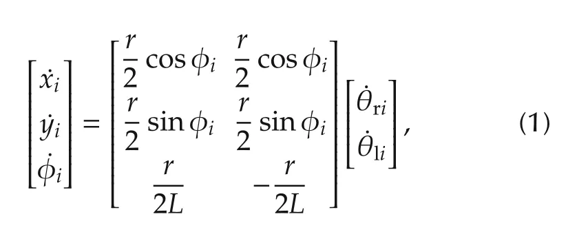
where (xi,yi) is the position of the ith robot measured at the center of wheels axel, φiis the heading of ith robot,andare the right and left angular velocities,respectively.
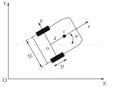
Fig.1 Model of two wheeled differential drive robot.
The dynamics of ith robot with n generalized coordinates and subjected to kinematics constraints can be given by this relation[21-23]:

where M(qi)∈Rn×nis a symmetric and positive definite matrix,is the Coriolis and centrifugal forces,G(qi) ∈Rnis the gravitational force, B(qi) ∈Rn×ris the transformation matrix,τiis the left and right motor torques. AT(qi) is the matrix associated with the constraint, λLi∈Rmis the Lagrangian constant. The kinematics constraints can be expressed as

Since the Lagrangian constants λLiare unknown,the system described by (2) can be transformed to a more convenient form for control purpose as follows:
Let Si(qi) be a full rank matrix (n-m) and has a set of smooth and linearly independent vector field that is obtained by spanning the null space of A(qi),i.e.,

From(3)and(4),we can find auxiliary vector ηi∈Rn-msuch that

where
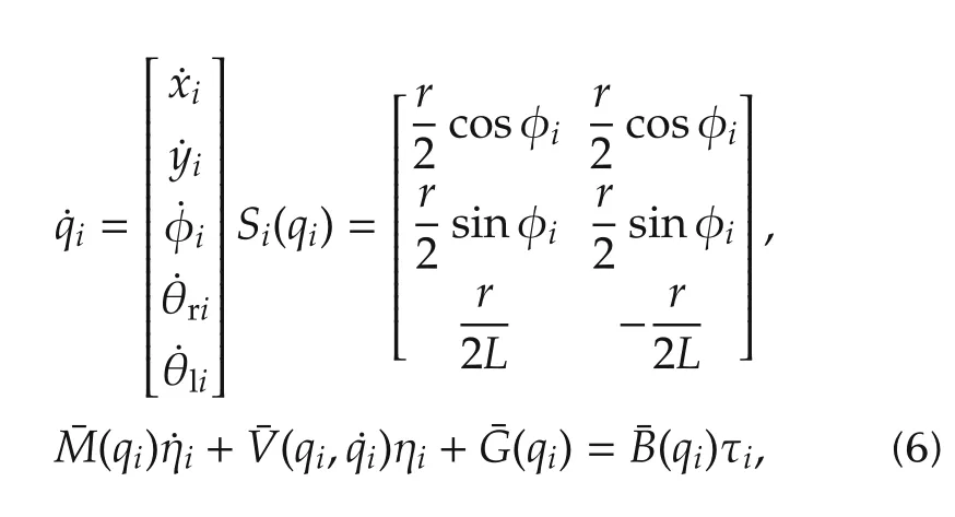
where
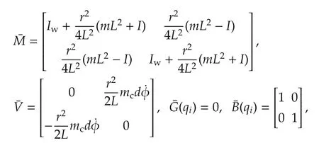
where m=2mw+mcand I=(Ic+mcd2+2mwL2+2Im).mcis the robot mass without motors and wheels,mwis the wheel mass with motor,Icis the moment of inertia of the robot about the vertical axis through the center of mass,Iwis the moment of inertia of each wheel with a motor about the wheel axis,Imis the moment of inertia of each wheel with a motor about the wheel diameter,r is the radius of each wheel,and L is half the length of the axel.The robots are identical with the same parameters.
3 Extended kalman filter(EKF)
Kalman filters (KF) are widely used in many applications due to their accuracy in providing an estimation with a minimum error to the states and parameters of systems.The estimation is essential for monitoring any change(fault)in the system behavior.For example,the fault information is given by taking the difference between the estimated and real parameters to produce residuals.The residuals are used for fault detection and diagnosis process.
In this study, we used a bank of EKFs set in parallel with the real dynamics; each one monitors a particular actuator in one robot,as shown in Fig.2.In our system,we have three EKFs. The first one is for the fault-free case.The second monitors the health status of the right actuator and the third monitors the health status of the left one.
Compared with other filtering techniques, EKFs can process all measurement data from sensors regardless of the associated noise and provide the best estimation to the parameters. Fig.3 shows a schematic overview to the mechanization of the EKF implemented by each filter in Fig.2.
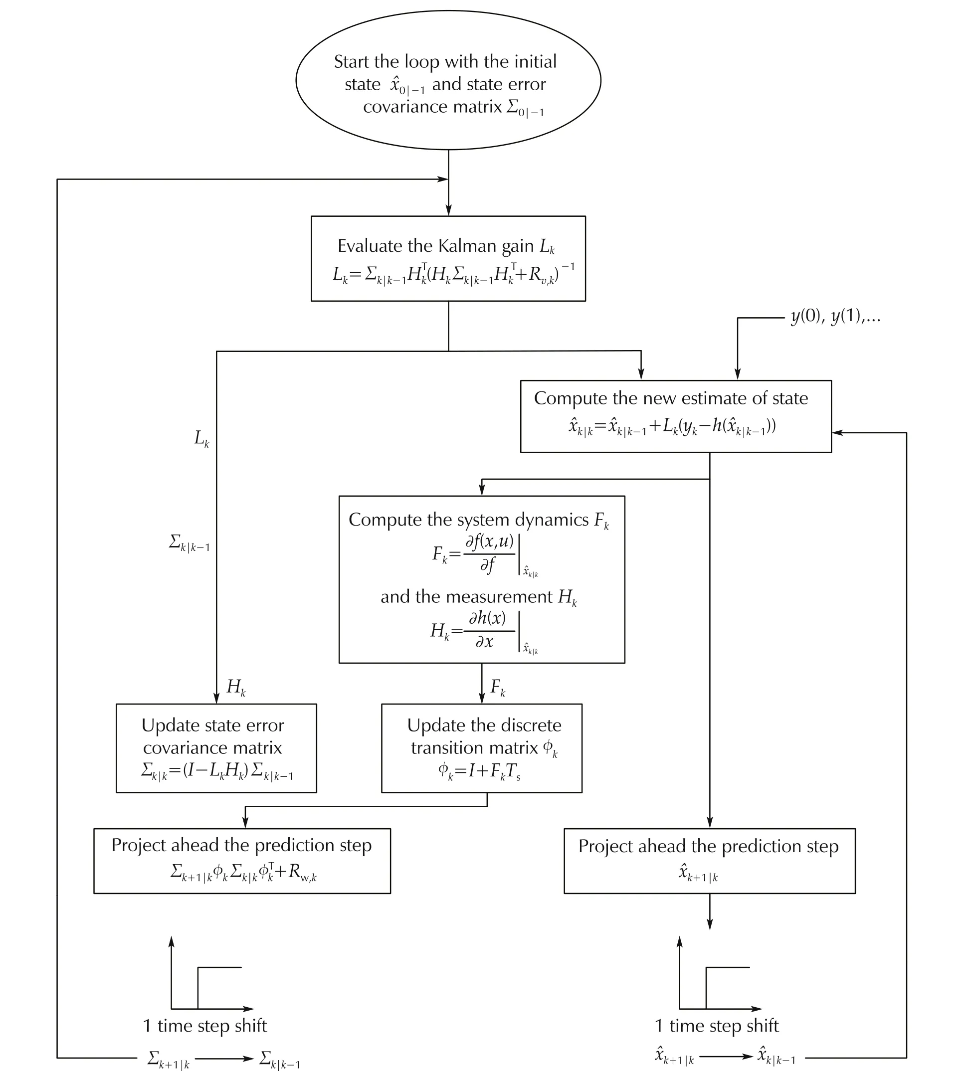
Fig.3 EKF algorithm[24].
3.1 Estimation of states and parameters
The EKF algorithm uses a set of nonlinear equations to estimate the states and faulty parameters of the system[24-26].The state vector of the jth EKF zjis augmented with the parameter of the mth actuator to monitor the occurrence of any failed motor.The mth actuator parameter is involved in the state vector to obtain a simultaneous estimation of the parameters and states of the robot.Hence,the state vector of jth EKF is given by

where xj=(xi,yi,φi)is the actual position of the robot,θmiis the faulty parameter with the index m indicates the location of the actuator under process to be either right or left.
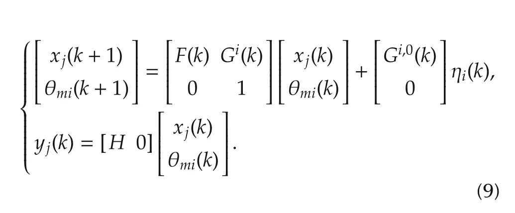
For the estimation process,the dynamics of the augmented state vector for the jth filter is represented in state space equations as

where ηin-iis the control input vector that includes the right and left angular velocities. After the linearization of the dynamics matrix Fkand the measurement matrix Hk, the system behavior is evaluated at each sampling time based on the following form:
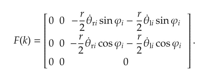
According to the dynamics of our system, we find the matrix F(k)by linearizing the robot’s equation in(1)as
In addition,the input matrices are defined from(1):
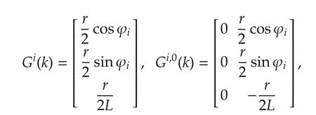
where Gi(k)is ith column of the input matrix G(k).Gi,0(k)is the input matrix G(k) with its ith column set to zero.Equation(9)is implemented by the EKF algorithm during the robot’s mission for each time step k.Consequently,the outcomes of the EKFs are used to determine the overall system’s behavior as shown in Fig.2.
3.2 Fault detection and isolation of mth actuator
By the EKFs, the faults can be detected and isolated immediately once occurred based on the hypothesistesting algorithm. This algorithm uses the error state covariance matrix Σjand the residuals rjto assign the conditional probability that defines the fault scenario δjand then assign the value for that fault.The accuracy of detecting undesirable events by EKF is very high because this filter has the capability of reconstructing a correct state vector even in the occurrence of faults. Then, the robot state is obtained by taking the sum of every filter estimate weighted by the corresponding probability[25].
The hypothesis-testing algorithm in Fig.2 assigns the probability to define the health status of the mth actuator.Then the state estimate vectorof the ith robot can be computed by taking the sum of all statesproduced by EKFs and weighted by their corresponding probabilities.


The density probability is a Gaussian function and described by the following formula:

where Ykis a measurement vector such that Yk= yk,yk-1,...,y0, M is the measurement dimension, δjrepresents the fault scenario on the mth actuator,rjand Σjare the residual signal and the state vector covariance matrix respectively computed by mth EKF. By examining the conditional probability (11), it becomes easy to determine the status of the mth actuator;and to define the fault scenario.
4 Distributed active fault tolerant control design(DAFTC)
DAFTC is proposed to accommodate actuator faults for n number of mobile robots shown in Fig.4. The proposed controller is a combination of the extended Kalman filter and sliding mode technique.The purpose of this control technique is to keep the robot tracking the trajectory in both fault-free and fault cases.
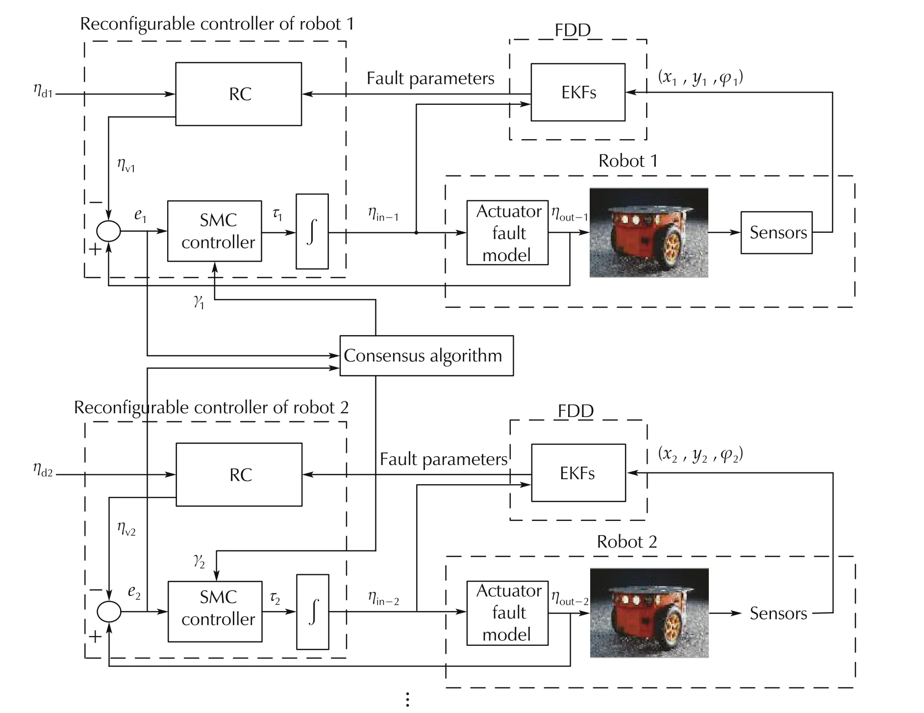
Fig.4 Overall system structure.
4.1 Actuator fault model
To accommodate the fault,we need to model the actuator fault and incorporate it into the dynamics of the robot.This model is introduced in(13)and its structure is presented in Fig.5.

where
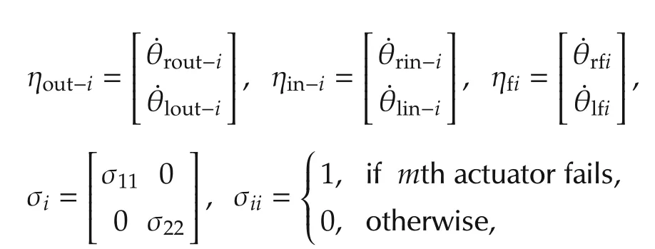
where ηout-iis the actual wheel angular velocity vector,ηin-iis the control input vector, σiis the probability of the fault occurrence in the mth actuator, and ηfiis the faulty angular velocity vector.

Fig.5 Actuator fault model.
Then, the dynamics (6) can be rewritten under two modes of operation as follows:

ηout-iis estimated by the EKF and provided to the controller to accommodate the fault as shown in Fig.4.ηout-iin(13)can be given in matrix form as
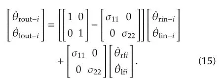
It is obvious from equation(15)that in the presence of a fault in the mth actuator in any one of the team members,the stability of the team formation will be affected.Therefore,we design a controller for each robot to track its wheel angular velocitiesand maintain the desired team formation.
4.2 DAFTC design
To design a controller that achieves the tracking goal,let us define the sliding surface sias follows[19]:

where n is the order of the system, λiand Ciare constants and are obtained accurately based on the dynamics of our system. Therefore the parameters are tuned and selected for acceptable contol performance in the fault-free and fault scenarios.eiis the angular velocities tracking error of ith robot such that

where ηυiis the wheel angular velocity vector that accommodates the ith robot fault.
To maintain the stability of the team formation when one of the robots is subjected to partial actuator fault,ηυiis given in(19)as a function of the LOCE factor of the faulty team member.However,in this study,we assume that only one of the team members could be subjected to partial or severe fault during the mission.
Then,for the control reconfiguration purpose,we let

where ζiis the LOCE factor of the faulty robot and sent to every healthy robot in the formation to move within the same capability of the faulty one.
Equation(19)can be used to reduce the capability of the healthy robots in the incidence of a partial actuator fault in a single robot or multiple robots during the mission. Nevertheless, the multi-robot faults problem will be investigated in more details in the future study.
From(19),we have

where ηdiis the desired wheel angular velocity vector,¯ηiis the magnitude of the injected fault in the faulty actuator. Then, equation (20) can be rewritten in matrix form:

From (21), ζifor the ith failed robot can be simply calculated as follows:

where m is the right or left wheel angular velocity.
To ensure the coordination between the team members such that ‖ei(t)-ej(t)‖ →0 t →∞, ∀(i,j), as we introduce local neighborhood tracking error as

where γi∈Rm(m=number of actuators in one robot),ejis the tracking error of a neighboring robot and given by ej=ηout-j-ηυj.aijis the weight between robot i and robot j as defined in Section 2.
Then, we introduce the coordination tracking error surface which includes both the angular velocities tracking error and local neighborhood tracking error for ith robot as[27]:

The goal is to design a DAFTC such that the wheel angular velocities tracking error and the local tracking error converge to zero in the free fault and fault cases. The control law τifor the ith robot is defined as

Theorem 1The wheel angular velocities error and the local tracking error for ith robot will asymptotically converge to zero,if the controller(26)is applied to dynamics(14).Consequently,the stability of the team formation will be achieved as t →0.
ProofLet us consider the Lyapunov function as

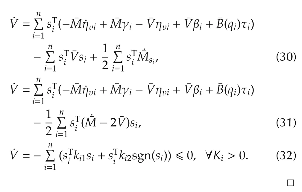
The differentiation of(26)is given by

Taking the derivative of (25) and substitute in (14), we obtain

Substitute(29)in(28),we obtain
The SMC is often irritated by high frequency oscillations known as chattering phenomena.In this study,the chattering is reduced in the overall system by replacing the sgn(s) with the saturation function sat(s) in (26).Although this is an effective way to reduce chattering but it cannot suppress it,as in the saturation itself there is signum function that persist, the saturation function can also be smoothed at the edges. The sat function is defined as follows:

where piis a small and positive number,i=1,2,....
From (32), it is clear that the sliding surface siis converging to zero.As,we have
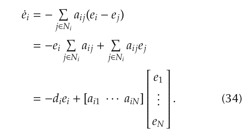
Defining the global error vector e=[e1··· eN]T∈RN,then the global error vector can be written as

Based on Gerˇsgorin Circle Criterion [20], the eigenvalues of the Laplacian matrix in(38)are in the left-half plane. This implies that the trajectories tracking errors converge to zero ‖ei(t)-ej(t)‖ →0 as t →∞and then overall system is stable.This is the end of the proof.
5 Formation reconfiguration mechanism
To have a reliable multi-agent system against actuator faults, it is very important to have that each team member detects and measures the severity level of the fault.
Remark 1The boundary of the fault can be changed according to the type of robots and the mission. There are no fixed values to define the fault for each type of robots. It can be simply specified in practice with testing the robots under different levels of fault.This enables the designer to define the fault boundary for the team assigned to accomplish a certain task.In our study,the boundary is selected based on the assumption introduced in the previous study having a similar type of robots and mission[18].
The severity level can be determined based on the LOCE factor ζias follows:
1) When ζi= 0, then all robots in the formation are free-fault and can simply continue the mission.
2)When 0 <ζi≤0.65,then the ith robot is subjected to a partial actuator fault,but it still has the capability to continue the mission with an acceptable performance.
3) When 0.65 <ζi≤1, this indicates that a severe actuator fault has occurred to the ith robot. Therefore,it must be excluded from the team due to its inability to keep its desired position in the formation.
5.1 Partial actuator fault
In the incidence of partial actuator fault,we solve the fault problem as follows:
1) The faulty robot sends a signal that carries information about its loss of control effectiveness factor to the healthy robots only when it meets the condition of 0 <ζi<0.65.
2) Each healthy robot reduces its velocities ηυionce receiving the factor ζiaccording to (19). This strategy enables the team members to move within the same capability of the faulty one in the existence of partial fault.Fig.6 shows an algorithm implemented by the robots in the presence of partial fault.For instance,let us assume that robot 2 which is labeled as R2 in Fig.6 is subjected to a partial actuator fault at some instant time. Then the associated algorithms of Fig.6 can be implemented to maintain the stability of the team formation in the presence of such faults.
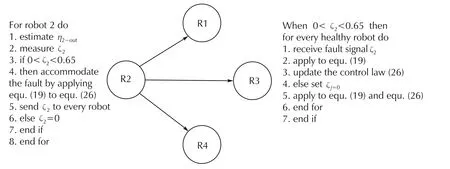
Fig.6 Implemented algorithms in the presence of partial fault.
5.2 Severe actuator fault
In the occurrence of severe fault,the reconfiguration of formation problem is solved as follows:
1) Each robot monitors the health status of other members in the formation by a vector called NRi. Each robot has one NRias shown in Fig.7.This vector represents the overall system’s health status and is obtained through the interaction among robots.Each single robot sends a value of 1 to all robots and receives 1 in a response to its signal from every one when there is no severe fault in the system.Otherwise,the returned value is zero.For example,if R2 is subjected to a severe fault,then R1 will receive a zero value in a response to its signal from R2 and given by NRi=[0 1 1].
2) According to the entries of NRireceived by each robot,the healthy robots update their reference trajectories and the local neighbourhood tracking error to form a suitable formation for the rest of the mission.
Algorithm implemented by robots in Fig.7 for monitoring the network
.Monitoring the operation status of motors
foreach robotdo
estimateby the EKFs;
measureζi.
if0.65 <ζi≤1then
switch off the motors to be excluded from the team formation;
sendto each robot 0 to let the healthy robots start reconfiguring their formation to a new geometric shape;
elsesend to each robot 1 to announce its healthy status.
end if
.Monitoring the health status of other robotsreceivecomponents of NRifrom each robot.ifNRi=[1 1 1]then
followthe reference trajectory states qd;
keepthe same coordination equation γi;
applyγito the control law(26);
elseif NRi=[0 1 1]then
updatethe reference trajectory states qd= qd1to relocate in a new position and build a predefined formation with the rest of robots;
updatethe coordination equation γito capture the new interaction between the robots according to the new desired formation shape;
applythe new γito control law(26).
...
end if end for
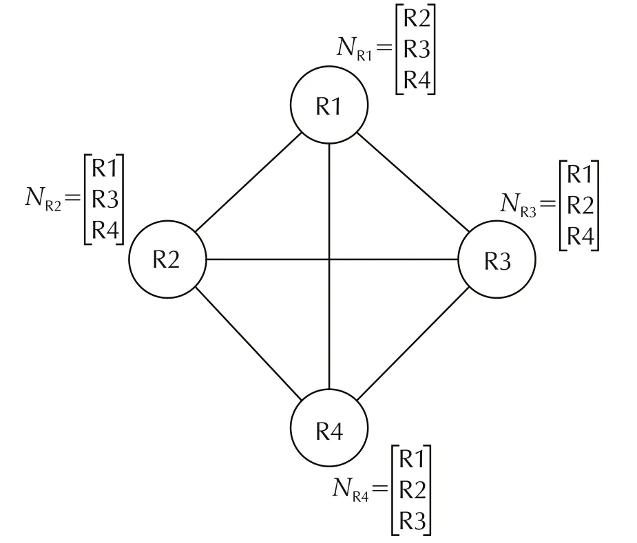
Fig.7 Monitoring overall system’s health status.
6 Experimental results
In this section, we demonstrate the effectiveness of our theoretical development in real time on four wheeled mobile robots. This experiment is performed on a flat terrain in the(GREPCI)lab in the electrical engineering department of ’Ecole de Technologie Sup’erieure(’ETS).
Remark 2Our proposed control strategy can handle multiple faults in the mission,no matter how many robots are involved. The same strategy can be implemented for successive failures.Thus,in our experiment,we examined our methodology to a single faulty robot to ensure that the robot can detect,diagnose and isolate the fault by itself.Moreover,the team members showed the capability to reconfigure their formation and continue the mission after the occurrence of a severe fault in one robot.
6.1 Experimental setup
Two wheeled differential drive robot is used for this experimental test. The wheels are actuated by DC motors of 6 V, 100 r·min-1installed on the right and left wheels. The wheels have radius of r = 3.3 cm. A radio frequency of NRF24L01 transceiver module is used for the communication between the control model implemented in Simulink Matlab with a sampling time of Ts= 10 ms and the physical robot to execute the proposed DAFTC in real time. The PC communicates with the robots through USB port connected with a communication circuit (ATmega328 & NRF24L01). NRF24L01 uses 2.4 GHz and can operate between 250 kbps and 2 Mbps. With lower baud rate, the communication can reach up to 100 m which is enough for testing our system in an indoor environment.The IMU sensor mounted in the middle of the axel gives the acceleration of the robot along the three axis x, y, φ to the onboard microcontroller which sends it back to the Simulink model for processing. ATmega328 microcontroller is used for processing the received and transmitted data for tracking the robot motion along the desired trajectory.Fig.8 shows a complete structure of our system.This structure contains a reconfigurable controller RC for each robot to accommodate any occurrence of actuator fault based on the online information given by the EKF.
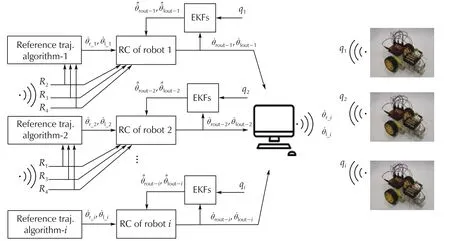
Fig.8 Real time setup.
The EKF uses the control input and the instant position from the physical robot to monitor any change in the motors’ behavior. In brief, each robot receives its motors’commands from the PC and map it into pulse width modulation PWM to power the two DC motors. Once the motors respond to the PWM signals, Atmega328 receives IMU measurements and send it to the PC for processing. In the PC, some information is extracted from the measurements, i.e., motors speed and robot position to keep tracking the desired trajectory in free fault and faulty cases.
The parameters of the ith mobile robot are given in Table 1.
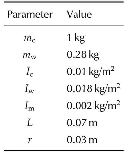
Table 1 Parameters of mobile robot.
6.2 Analysis of experimental results
6.2.1 Partial actuator fault scenario
In this scenario,we injected a fault to the right actuator of the second robot at instant time 20 s. The subjected fault caused a loss of 40%of the control effectiveness at the right motor. As a result, the second robot and the other team members deviated from their reference trajectories and the predefined team formation. The EKFs estimated the parameters of the faulty robot before and after the fault occurrence as presented in Fig.9.
The fault was detected immediately after its occurrence as shown in Fig.10(a).Then that fault was isolated or identified at the right motor at time 20 s as shown in Fig.10(b). Since there was no fault on the left motor,the signal remains at zero in Fig.10(c). Fig.11 shows the measurement of the LOCE factor at time 20 s,which is based on the online information presented in Figs.9 and 10.
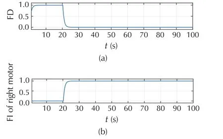
Fig. 10 Probability of the fault detection and isolation for robot 2.
6.2.2 Reconfigurable control results
In this section, we present the results of the reconfiguration mechanism that is applied to eliminate the effect of the right motor fault in the second robot. This mechanism utilizes the online information of the estimated right wheel angular velocityprovided by the FDD algorithm to accommodate the fault by adjusting the control law of the healthy actuator.
Since the LOCE factor is less than 65%,then the second robot still has the capability to achieve the mission with degraded performance.Therefore,the speed of the left actuator is reduced to let the second robot continuing the mission with 60% of its capability as shown in Fig.12. Moreover, the capability of the remaining healthy robots are reduced to move within the same capability of that faulty one as shown in Fig.13. Fig.14 shows the accommodation of a fault at the right motor of robot 2 once detected at time 20 s.
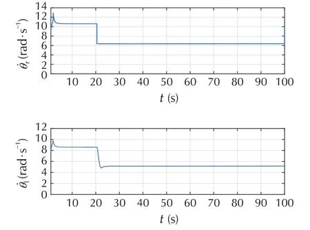
Fig. 12 Actual angular velocities of robot 2 before and after the reconfiguration mechanism.
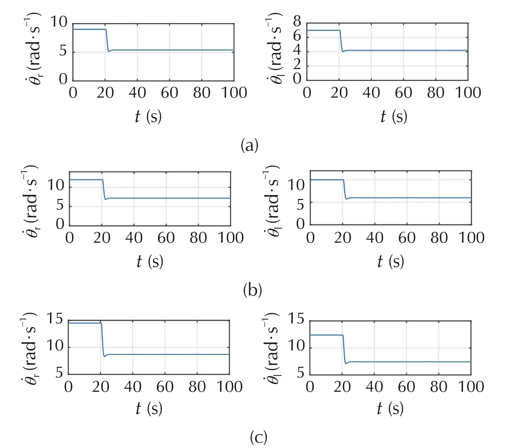
Fig. 13 Motors speed of healthy robots before and after the occurrence of fault in robot 2.
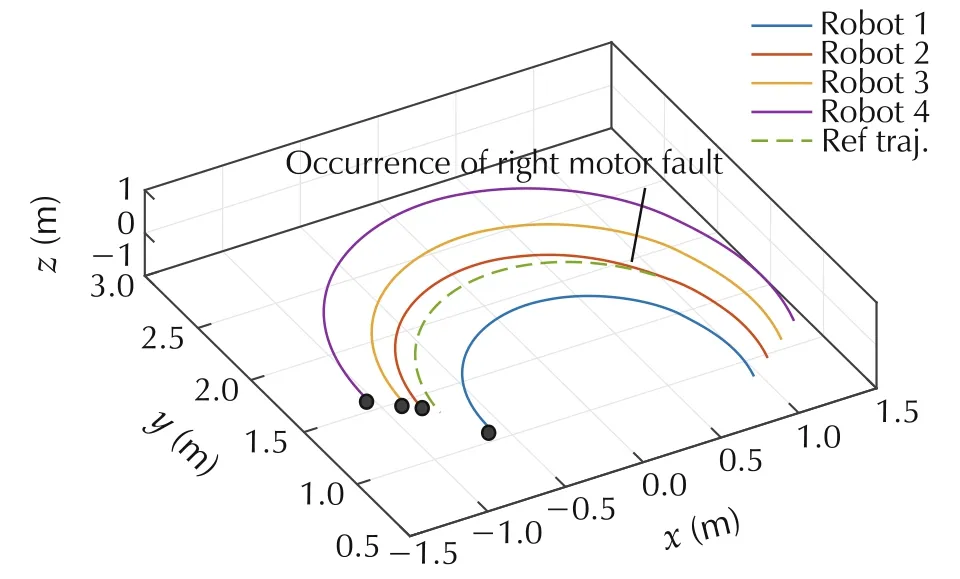
Fig. 14 Actual trajectory tracking for a team of four robots under partial fault case.
Consequently,the other team members kept tracking their reference trajectories well in the presence of the injected fault.
6.2.3 Severe actuator fault scenario
The effectiveness of our proposed controller was also tested in the presence of severe fault. In our test, we injected a fault that caused a 70%of LOCE in the left actuator of robot 2 at instant time 25s as shown in Fig.15.Thus, the fault was detected and isolated by the EKFs presented in Fig.2. Fig.16 shows the outcomes of the hypothesis testing algorithm in Fig.2.As it can be seen from Fig.16(a),the fault was detected immediately once occurred in robot 2. Simultaneously, the fault was isolated based on the results shown in Fig.16(b)and(c)of monitoring the right and left motors respectively.
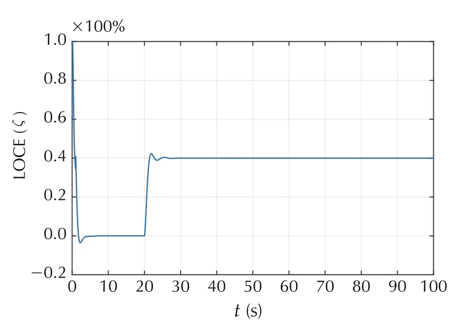
Fig.15 Measuring a loss of control effectiveness factor in robot 2.
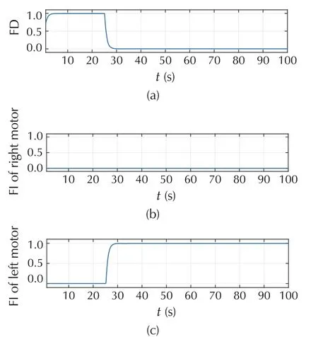
Fig. 16 Probability of the fault detection and isolation for robot2.
Fig.16(b) and (c) introduce the values of matrix σiwritten in(13)and by these values,the faulty robot can locate the source of the fault and send its information to the controller in order to take an appropriate action that enables the team to continue the mission.Since the left actuator experienced a severe fault, the algorithm implemented by each team member in Fig.7 enabled the faulty robot to be excluded immediately from the team formation as shown in Fig.17. The remaining healthy robots received a signal of zero value from robot 2 and accordingly each robot updates its reference trajectory and relocates itself to a new position in the formation.As it can be seen from Fig.17,robot 1 updated its reference trajectory and continued the mission with robots 3 and 4 after the occurrence of a fault in robot 2.
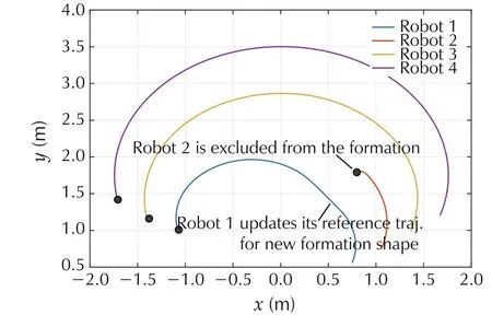
Fig. 17 Actual trajectory tracking for a team of four robots under severe actuator fault case.
7 Conclusions
In this study, we proposed DAFTC system for multiple wheeled mobile robots against partial and severe loss of control effectiveness in the presence of perfect communication network. The proposed control strategy is a combination of the extended Kalman filter EKF and sliding mode controller SMC. This control strategy is applied to each robot so that any robot can detect,diagnose and eliminate the fault by itself. Real time experimental results demonstrated the effectiveness of our proposed approach.
Future work includes the design of DAFTC for the multiple actuator faults under perfect communication network. Since we consider this kind of problems, the obstacle avoidance algorithm will be included in the system to avoid the collision between the healthy robots and the faulty ones. Then, the problem of designing DAFTC against partial and severe actuator faults in the presence of a time delay in the exchanged information between team members will be investigated.
杂志排行
Control Theory and Technology的其它文章
- Optimization management of hybrid energy source of fuel cell truck based on model predictive control using traffic light information
- Predictive car-following scheme for improving traffic flows on urban road networks
- Two-stage on-board optimization of merging velocity planning with energy management for HEVs
- A unified optimal planner for autonomous parking vehicle
- An MPC-based manoeuvre stability controller for full drive-by-wire vehicles
- Robust control for electric vehicle powertrains
