An MPC-based manoeuvre stability controller for full drive-by-wire vehicles
2019-12-09PingWANGZiyangLIUQifangLIUHongCHEN
Ping WANG, Ziyang LIU, Qifang LIU†, Hong CHEN
1.The State Key Laboratory of Automotive Simulation and Control,Jilin University,Changchun Jilin 130025,China;
2.Department of Control Science and Engineering,School of Communication Engineering,Jilin University,Changchun Jilin 130025
Abstract Aiming at the actuator time delay caused by the drive-by-wire technology, a novel manoeuvre stability controller based on model predictive control is proposed for full drive-by-wire vehicles. Firstly, the future vehicle dynamics are predicted by a twodegree-of-freedom vehicle model with input delay.Secondly,in order to prevent the vehicle from destabilizing due to excessive side slip angles,the determined ideal yaw rate and side slip angle are tracked simultaneously by optimizing the front wheel angle and additional yaw moment.Moreover,in order to improve the trajectory tracking ability,a side slip angle constraint determined by phase plane stability boundaries is added to the cost function.The results of Matlab and veDYNA co-simulation show that the regulated yaw rate can track the reference value well and the side slip angle decreases.Meanwhile,the trajectory tracking ability is improved obviously by compensating the time delay.
Keywords: Drive-by-wire technology,networked control system,model predictive control,stability control,time delay
1 Introduction
With the development of electric vehicles, more and more new technologies have been developed, such as drive-by-wire technology,active front steering(AFS)system and in-wheel motor drive system. The drive-bywire technology replaces the traditional mechanical control systems with electronic control systems [1], and the control signals are transmitted through a real time communication system.Then electronic stability control(ESC)system is a typical networked control system.To prevent over and under-steering,AFS system makes the front wheels turn a certain number of degrees in accordance with the speed of the vehicle.An electric vehicle(EV) with multiple motors can generate a direct yaw moment quickly by applying a driving torque to different wheels,because the response speed of the motor is within 10 milliseconds[2,3].They provide more degrees of freedom of automotive electronic control system,and cause some new problems.
With a combination of active steering and full state feedback control, a vehicle’s handling characteristics can be arbitrarily tuned to driver preference as well as to maintain desired behavior when operating conditions vary [4]. However, this drive-by-wire system is integrated and networked by some ECU nodes, then the delay time of message transmission in communication cycles will affect the vehicle performance directly.The influences of time delay on vehicle handling and stability of the driver-vehicle closed-loop system were discussed in[5].In[6],based on a vehicle yaw dynamics model including the actuator saturation and delay,a linear quadratic controller was proposed to improve the tracking performance of the vehicle.The time delay was described as the modification term of the tracking error. However, once excessive side slip angles or excessive differences in the actual and desired yaw rates are detected,the vehicle has already entered an unstable state[7].At this time,the ESC can do nothing to prevent the vehicle from spinning or migrating from its desired trajectory.To solve this problem,model predictive control (MPC) has been used to stabilize the yaw moment of a vehicle by considering the near-future safety constraints and dynamics[7-12].Meanwhile,MPC has excellent properties at handling delay[13,14]and in other applications[15,16].
Therefore, by considering the actuator time delay caused by the drive-by-wire technology, a novel manoeuvre stability controller based on model predictive control is proposed for full drive-by-wire vehicles.In the framework of model predictive control, the constraint of side slip angle is considered through the phase plane stability boundaries, then the control requirements are converted to the objective function. By optimizing the front wheel angle and additional yaw moment online,the vehicle yaw rate and side slip angle can track the expected value accurately.
The paper is organized as follows. In Section 2, the vehicle model, and reference model are discussed. In Section 3, the design process of the stability controller is given. Then its performance is evaluated by cosimulation of veDYNA and Matlab in Section 4. Finally,we conclude our research in Section 5.
2 Related models
2.1 Vehicle model
A 2DOF yaw plane vehicle model is considered, in which only the vehicle lateral and yaw motion are taken into account, then we assume that the longitudinal speed of EV is constant. At front and rear axles, the left and right wheels are lumped into a single wheel.Driver can only steer the front wheels and the steering angles of two front wheels are equal to each other. In this way, the model of vehicle is simplified to a bicycle model,shown in Fig.1[17].
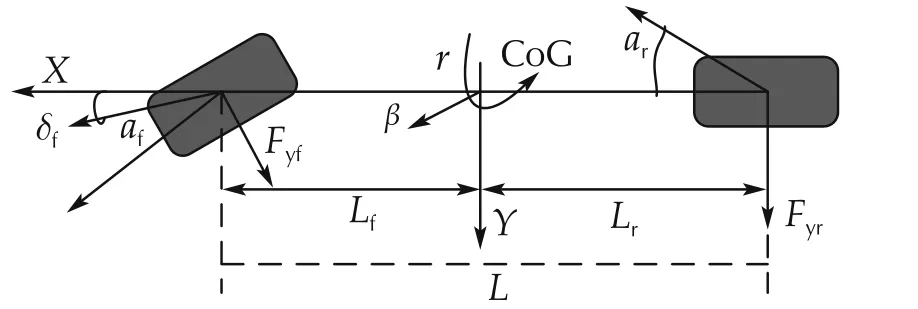
Fig.1 Two degree-of-freedom vehicle model.
Considering the delay τcaused by drive-by-wire technology,the bicycle model with input time delay is shown as
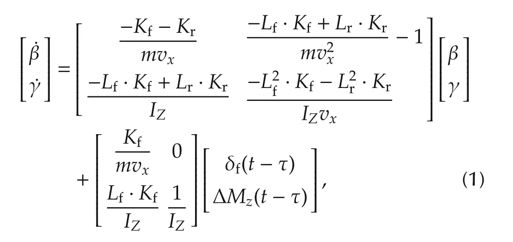
where β(rad)is the side slip angle,γ(rad/s)is the yaw rate,δf(rad)is the front wheel angle,and ΔMz(Nm)is the additional yaw moment. Other vehicle parameters and their values are shown in Table 1.
We define the upper limit value of β as βup=|arctan(0.02μg)|[18],the upper limit value of γ as γup=[18], the maximum front wheel angle as δmax,and the maximum additional yaw moment generated by the motor as ΔMmax. Then, the system state is defined asthe control input asand model (1) can be represented as the following state-space model:

where
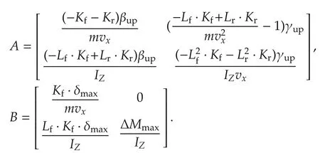
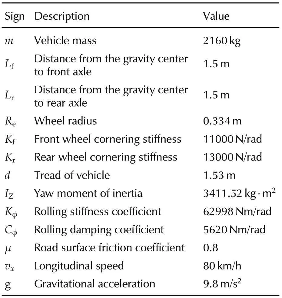
Table 1 Vehicle parameters.
2.2 2DOF reference model
The desired yaw rate and side slip angle should be defined by the desired steering angle. When the additional yaw moment ΔMz, as the control input, assume that ˙β = 0 and ˙γ = 0 about the reference signal, a 2-DOF linear model of the yaw rate γ and side slip angle β dynamics is considered here:
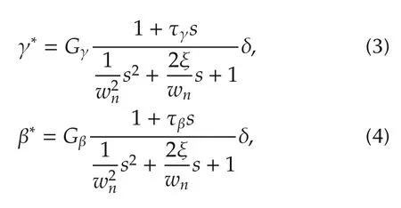
where the steady-state yaw rate gain
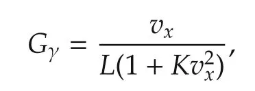
the steady-state side slip angle gain

the differential coefficients

the undamped frequency
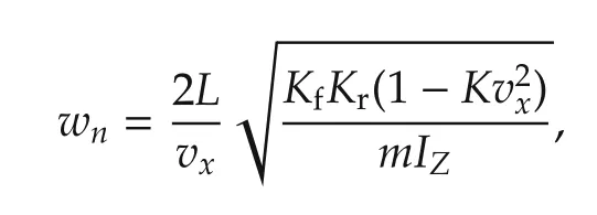
the damping coefficient

the distance from the front to rear axle L=Lf+Lr,and the stability factor

Considering the tire-road friction coefficient μ, the limitations of the yaw rate and the side slip angle are given as follows[18,19]:

3 Model predictive control strategy
Considering the input time delay,a model predictive controller is designed to track the desired values of γ*of the yaw rate and β*of the side slip angle given by the reference model.The state and input constraints are considered to achieve better performance. The control scheme is given in Fig.2. The additional yaw moment generated by the designed MPC controller is distributed and added to the basic motor drive torque.
3.1 Predictive model
By discretizing (3) at the sampling instants kTs, the discrete-time model is given as
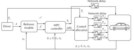
Fig.2 Scheme of MPC strategy.
where

Define the discrete-time integrator of the control and state variables as

Then the incremental form of model(5)is given as

which is the basic model of the MPC controller designed in the next section.
3.2 Prediction of future dynamic behavior
At time k, the future dynamics are predicted based on model (6) and the initial condition x(k). Define the control horizon and prediction horizon of the system as N (N >τ′). Due to the causal relationship between the control inputs and the system outputs, the control input sequence is divided in two parts, which are the optimization variable
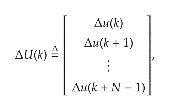
and the known input
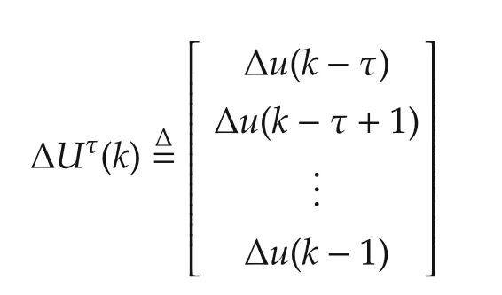
at time k.
Therefore,the future yaw rate X1(k+1|k)is described as follows:

where
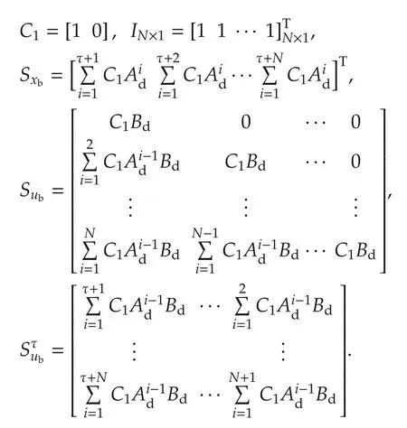
Following the similar process, we replace C1by C2=[0,1],then the future side slip angle X2(k+1|k)is described as

3.3 Optimization and feedback control
The main control objective is to track the reference value of yaw rate and the side slip angle as soon as possible to improve the stability performance.Then,the cost function is given as follows:

Moreover, with regard to the cost function related to energy consumption,the third term about the future control input is defined as

where
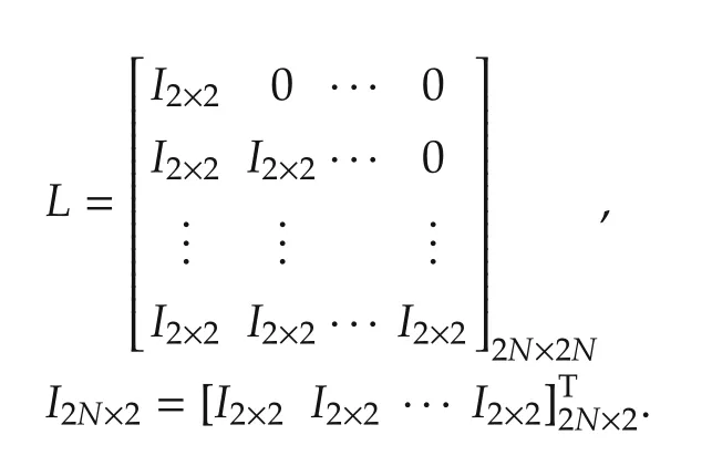
When the side slip angle exceeds a certain value,the vehicle is very difficult to manipulate. Therefore, the state constraint on side slip angle x1should be considered as

The boundary x1minand x1maxis determined by phase plane analysis of side slip angle in Fig.3[20].
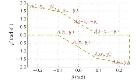
Fig.3 The reference diagram of the phase plane.
Due to actuator saturation,the motor torque and the front wheel angle are bounded.Based on the definition of control input u,the control input constraint is

In this case, the MPC strategy is described by the following optimization problem:
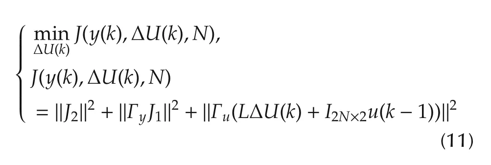
subject to (9) and (10), where Γyand Γuare weighting factors.
The optimization problem (11) with the constraints can be formulated as a quadratic programming (QP)problem

where
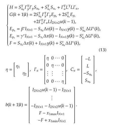
By solving the above problem, the optimal control input Δu*(k) is submitted to u*(k) = Δu*(k)+u(k-1).Furthermore, the optimal control inputis used to calculate the additional motor drive torques ΔTcfl,ΔTcfr,ΔTcrl,and ΔTcrr,as

4 Simulation
To verify the reliability of the proposed control scheme, simulations of the distributed driving of EVs with veDYNA/Simulink are performed. Double lane change (DLC) maneuver is established in the simulations. The parameters of the full-vehicle model in ve-DYNA are given in Table 1. The basic control parameters are as:the sampling period Ts=0.001 s,the control horizon and prediction horizon N = 25, the maximum front wheel angle δmax= 0.15 rad, the maximum additional yaw moment ΔMmax= 5000 Nm [21], the time delay τ= 0.018 s [22]. In order to achieve the performance from the proposed strategy,practical parameter selection criteria are required. Here, we select several indicators shown in Table 2 to objectively evaluate the performance of the vehicle. The threshold value Yupof lateral displacement Δypis its maximum deviation from 0 to t.
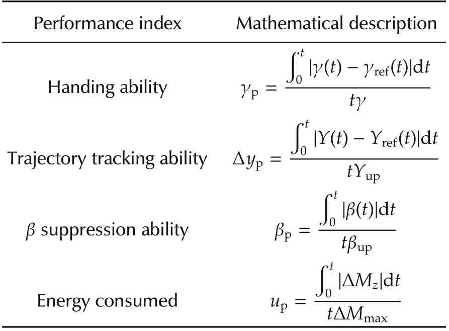
Table 2 Performance evaluation indices.
4.1 Analysis of the weighting parameter
The cost function(11)describes not only the requirements for the handling ability,but also the requirement for energy consumption.Moreover,the trajectory tracking ability of the vehicle must be guaranteed as much as possible. The balance between the above performance is adjusted by the weighting parameters. We choose Γy= 0.6IN×N, and η1= 0.22. Then we analyze the influence of the change of weight coefficient η2on the system, as shown in Figs.4-7. If η2is increased or decreased, the additional yaw moment will also decrease or increase accordingly.We compare the system performance with η2=0.025,0.05,and 0.1,respectively.
When η2= 0.025, the yaw moment has oscillated viciously. Meanwhile, as shown in Figs.4 and 5, more energy causes the larger yaw rate and side slip angle.Correspondingly,a larger front steer angle is needed,as shown in Fig.7.When η2=0.1,a smaller yaw moment with less actuation energy will be conducted on the vehicle.However,the ability of restraining the side slip angle shown in Fig.5 is reduced obviously. When η2= 0.05,the vehicle performance including handing stability, β suppression ability is satisfied with the smaller energy consumption.
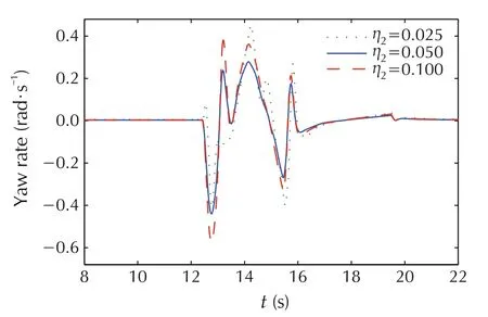
Fig.4 The yaw rate with different η2.
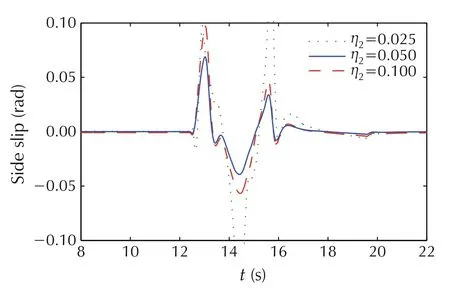
Fig.5 The side slip angle with different η2.
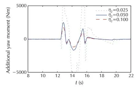
Fig.6 The additional yaw moment with different η2.
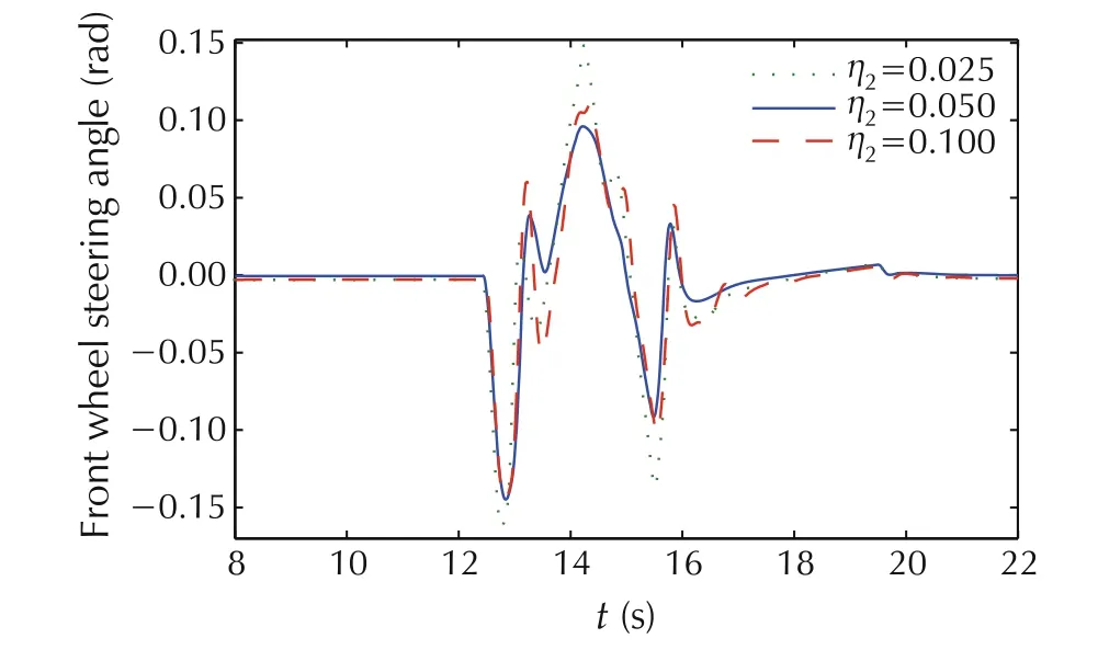
Fig.7 The front steer angle with different η2.
4.2 Analysis of the state constraint
The constraints on the side slip angle are used to keep the vehicle instable driving conditions.Usually,the fixed boundary values are used to limit the tire side slip angles to the linear region of the tire model. However,according to the phase plane analysis, a more flexible and less conservative boundary value of the side slip angle is given in this paper.The vehicle performance with different boundary values is compared.
By comparing the effect of state constraint on yaw rate tracking in Fig.8, we can see that the MPC controller with fixed constraints reduce partial tracking performance, and the MPC controller with adaptive constraints is not like this. Meanwhile, when the side slip angle constraint is enabled,the ability to track the target path is enhanced.Fig.9 shows the side slip angles with different constraints. The corresponding control inputs are given in Fig.10. It can be seen that the MPC controller with adaptive constraints has a better β suppression ability and consumes less energy.
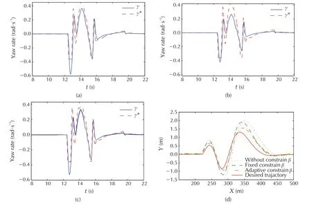
Fig. 8 Simulation results of yaw rate with state constraints. (a) Yaw rate without state constraints. (b) Yaw rate with fixed state constraints.(c)Yaw rate with adaptive state constraints.(d)The trajectory tracking compare.
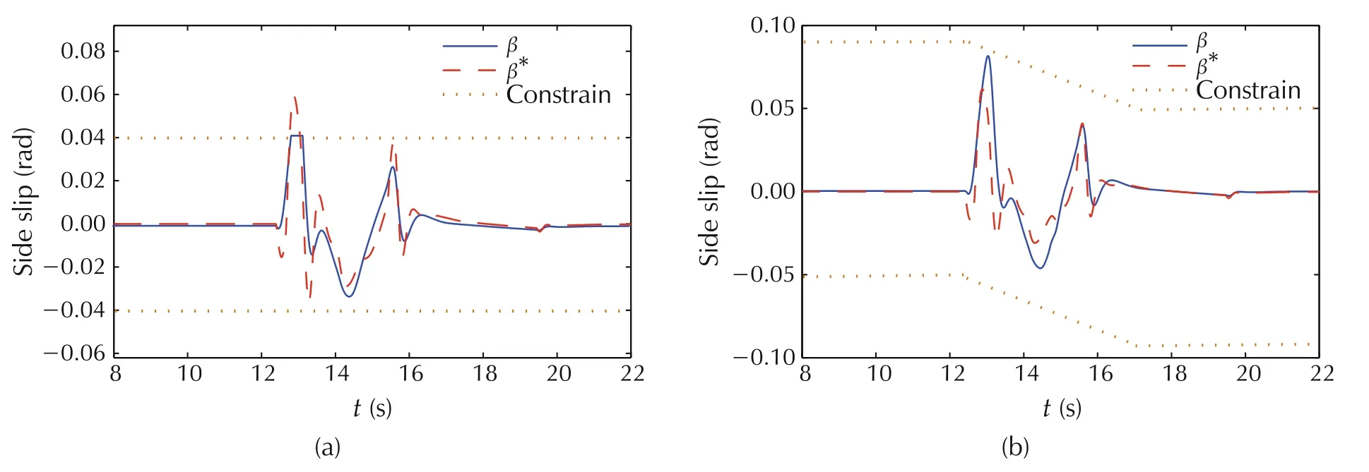
Fig.9 Simulation results of side slip angle with different state constraints.(a)Sideslip angle with fixed state constraints.(b)Sideslip angle with adaptive state constraints.
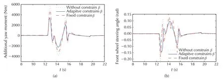
Fig. 10 Simulation results of control value of state constraints. (a) The additional yaw moment with different state constraints.(b)The front steer angle with different state constraints.
4.3 Analysis of the time delay compensation
In the MPC framework,the predicted outputs(7)and(8)consider the effect of the input time delay on the vehicle performance. The results in Figs.11-13 show that the MPC controller with time delay compensation gives less overshoot,shorter response time,better stability and trajectory tracking ability than the other one.
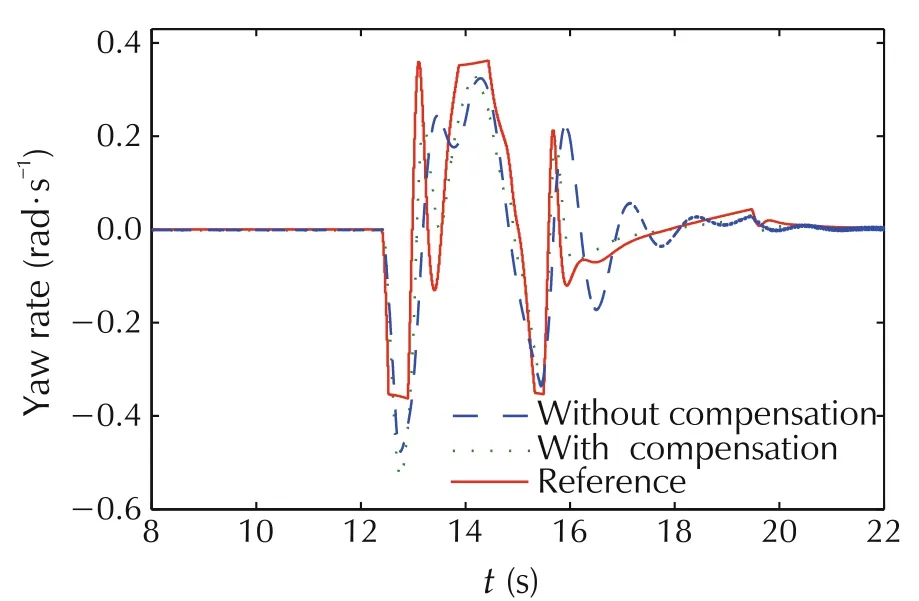
Fig.11 The yaw rate with and without time delay compensation.
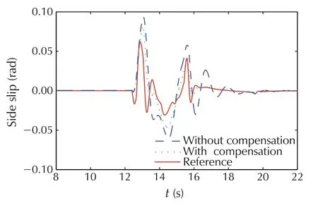
Fig.12 The side slip angle with and without time delay compensation.
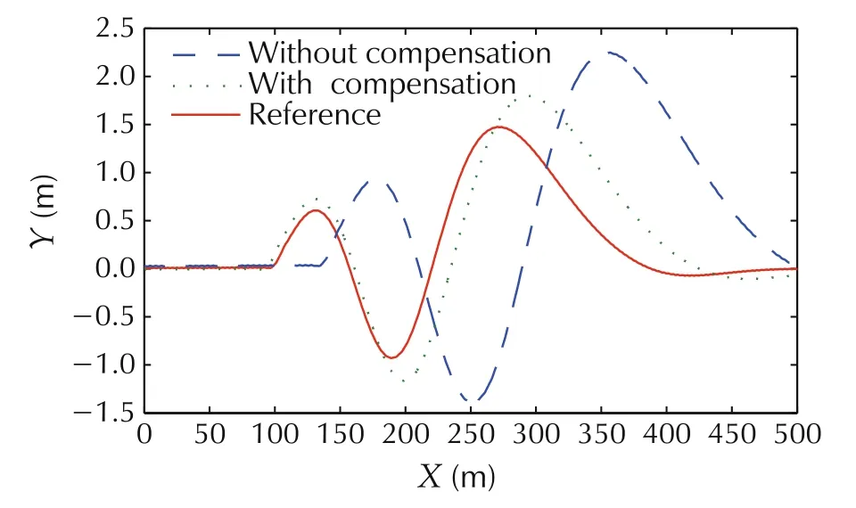
Fig. 13 The trajectory tracking result with and without time delay compensation.
5 Conclusions
Considering the input time delay caused by the driveby-wire technology,an MPC controller for vehicle stability enhancement was proposed in this paper. The optimal additional yaw moment and front wheel angle under safety and energy constraints was obtained based on the ideal yaw rate and side slip angle.Using a series of simulation results for DLC slalom maneuver,guidelines for control parameter selection were given. The results of Matlab and veDYNA co-simulation show that the regulated yaw rate can track the reference value well,the side slip angle was suppressed and the consumed energy decreased. Meanwhile, the trajectory tracking ability is improved obviously by compensating the time delay.
杂志排行
Control Theory and Technology的其它文章
- Optimization management of hybrid energy source of fuel cell truck based on model predictive control using traffic light information
- Predictive car-following scheme for improving traffic flows on urban road networks
- Two-stage on-board optimization of merging velocity planning with energy management for HEVs
- A unified optimal planner for autonomous parking vehicle
- Distributed active fault tolerant control design against actuator faults for multiple mobile robots
- Robust control for electric vehicle powertrains
