The spatial evolution of velocity and density profiles in an arrested salt wedge
2019-12-01AdamYangTedfordLawrence
Adam J.K. Yang, E.W. Tedford, G.A. Lawrence
Department of Civil Engineering, University of British Columbia, Vancouver, BC V6T1Z4, Canada
Keywords:Arrested salt wedge Internal hydraulics Shear layer Asymmetry
A B S T R A C T The spatial variation in the properties of an arrested salt wedge have been investigated, both analytically and in the laboratory. In the laboratory particle image velocimetry and laser induced fluorescence were used to obtain flow velocities and the height of the density interface. An analytical solution for the profile of interface height, in the absence of interfacial instabilities, has been developed from two-layer internal hydraulic theory. The evolution of the velocity profile is predicted using a momentum diffusion equation following a Lagrangian frame of reference along the interface of the salt wedge. The centre of the shear layer is predicted to lie above the density interface, with this offset decreasing in the downstream direction. Our theoretical predictions are in good agreement with our laboratory measurements.
Salt wedges often intrude tens of kilometres upstream into rivers and estuaries, where they significantly influence water properties and circulation [1]. The length and structure of a salt wedge varies with the river discharge and the strength and phase of the tide [2, 3]. During flood tide the advancing intrusion is reminiscent of a gravity current with a distinct head; whereas, during slack and ebb tide it is more wedge-like, akin to the laboratory realisation of an arrested (or stationary) salt wedge presented in Fig. 1.
Many studies have focussed on predicting the length and shape of arrested salt wedges, by using internal hydraulic theory with a shear stress applied at the interface between the fresh and salt layers [5–10]. The resulting predictions are sensitive to the value of the interfacial friction factor [10]. Attempts to relate the interfacial friction factor to bulk flow properties such as the Reynolds number and the densimetric Froude number are subject to considerable scatter [5].
It is important to recognize that hydrodynamic instabilities on the interface, see Fig. 1, contribute to the interfacial shear stress and to mixing between the layers [2–4, 10–13]. The nature of these instabilities is sensitive to the details of the velocity and density profiles which evolve along the length of the salt wedge.These profiles often exhibit asymmetry in that the centre of the velocity interface is located above the density interface; for example, see the field surveys by Geyer and Farmer [2] (Fig. 6) and Giddings et al. [14], and the laboratory experiments of Yonemitsu et al. [4]. In asymmetric flows interfacial instabilities cusp predominantly into the layer where the vorticity is concentrated [15]; whereas, in symmetric flows interfacial instabilities cusp into both layers [16]. Both types of instability can be present in a given salt wedge (see Fig. 1 and Refs. [3, 4, 13]). It is our longterm goal to investigate interfacial instabilities in arrested salt wedges and the mixing associated with them. However, before we can do so we need to understand the mean flow structure of arrested salt wedges.
The hydraulics of two-layer flows is described in Ref. [17].The key parameter is the composite internal Froude number:

with the layer Froude numbers,

where the subscript i = 1 is the upper layer, and i = 2 represents the lower layer (see Fig. 2). The cross-sectionally average velocities, densities, depths are represented by ui, ρi, and yi,respectively. The reduced gravity, g′= gϵ, where ϵ =(ρ2−ρ1)/ρ2.In our experiments ϵ ≪1, and we can assume that the total depth H = y1+ y2is constant.
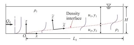
Fig. 2. Schematic of arrested salt wedges
The composite internal Froude number represents the ratio of a convective velocity to a long-wave phase speed in a two-layer fluid [18]. In supercritical flow (G2> 1), the convective velocity is greater than the long-wave phase speed and waves can only propagate in one direction, downstream. In subcritical flow(G2< 1), waves may propagate in both directions, upstream and downstream. At internal hydraulic controls (G2= 1) the flow speed is equal to the long-wave speed. In this study, the exit at the right end of the channel (mouth of the estuary) imposes such a control.
The salt wedge intrudes upstream (right to left) against the fresh water flow (Fig. 2). In the following, the entrainment from the lower layer to the upper layer is assumed to be negligible,such that the lower layer velocity u2≈0 for the steady arrested salt wedge. At the tip of salt wedge, the river Froude number is given as

where UR= QR/(BH), QRis the river discharge rate and B is the width of the channel (constant).
Following Refs. [9], and [19–21], the effects of friction in twolayer flows can be accounted for using:

where EIis the Bernoulli constant, Sfis the friction slope and x is the horizontal distance from the tip of salt wedge.
Assuming that Bernoulli's equation holds for each layer, the Bernoulli constant is

The assumption that u2= 0 allows us to ignore bottom friction and consequently the friction slope is [20]

where fIand fware friction factors for the interface and the sidewalls, respectively.
Substituting Eq. (5) into Eq. (4) yields the slope of the density interface

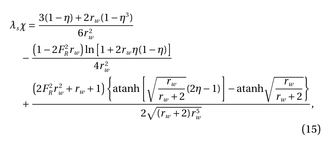
Substituting Eqs. (3) and (6) into Eq. (7) yields

where

and Lsis the length of the arrested salt wedge.
We can solve Eq. (8) by integrating and applying the boundary conditions at the tip of the salt wedge:

and at the internal hydraulic control at the mouth of the estuary:

The special case where the sidewall friction is negligible (i.e.rw= 0) has been examined by Refs. [6], [8], and [10]. In this case,Eq. (8) becomes

Integrating Eq. (12) and applying the tip boundary condition Eq. (10) yields

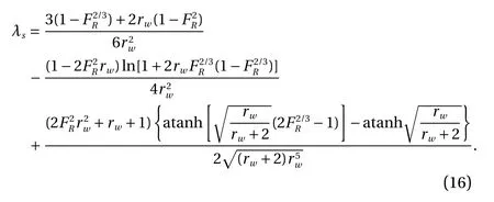
Applying the internal hydraulic control condition Eq. (11),we find that the non-dimensional length of the salt wedge is given by

and applying the internal hydraulic control condition Eq. (11)gives
To examine the vertical variation of the velocity, a new Cartesian coordinateis located at the density interface and is tangential and normal to the density interface (Fig. 2). This frame of reference follows the movement of a neutral tracer along the density interface, and the interface is assumed to be rigid. We determine the velocity profile by solving the momentum diffusion equation

where ν∗= kν is the effective viscosity, t is the travel time of the moving frame of reference, and the coefficient k incorporates the suppression of momentum diffusion by the stable stratification, the interfacial waves, and a weak reverse flow in the lower layer. The velocity profile is assumed to evolve independently of the proximity of the bottom of the channel and the water surface.
The fundamental solution (Green function,of the diffusion equation, Eq. (17) is

We may now solve for velocity as

where s is a dummy variable, andis determined experimentally at the tip of the salt wedge (see below).
The travel distance and time (t) from the tip of the salt wedge are approximately related by

Laboratory experiments were conducted in a 370 cm long and 106 cm wide tank divided into two equally sized reservoirs and connected by a 10 cm wide channel as shown in Fig. 3. The front panel of the 200 cm long channel is made of Plexiglas for visualization. Prior to each experiment, the water was well mixed in the reservoirs to ensure a uniform temperature of approximately 20 °C. A removable gate was placed mid channel to separate fresh water (left hand side) from salt water (right hand side).
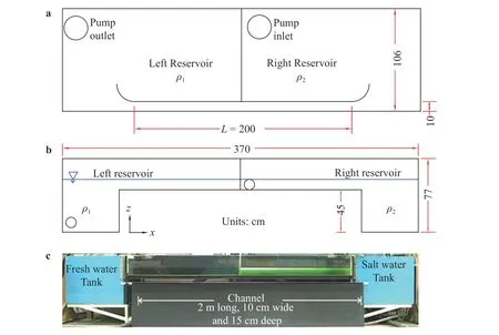
Fig. 3. a Plan, b side view and c photograph of the experimental set up. A fresh water tank is on the left and a salt water tank is on the right. A transparent channel connecting the two tanks is divided by a removable gate at its centre. A pump draws saline water from the right reservoir and discharges it into the base of the left reservoir to create a fresh water flow. A fixed downward-radiating laser sheet was generated along the centre of the channel. Saline water mixed with Rhodamine WT dye was illuminated by the light sheet

Table 1 Experimental parameters
Laser-induced fluorescence (LIF) was used to visualize the density interface along the whole channel by illuminating Rhodamine WT dye in the salt water (lower layer) with a continuous solid state laser (530 nm). The laser beam was passed through a Powell lens to generate a downward-radiating light sheet along the centre of the channel. Colour images were collected to allow for the separation of the signals (red, green and blue) for simultaneous particle image velocimetry (PIV). The interface was identified by locating the maximum vertical gradient in light intensity. The measured interface height is known to approximately 0.1 mm, the pixel size. PIV was used to measure the velocity of pliolite VT-L particles (Goodyear Chemical Co.). The particles were pulverized and sieved to obtain those with diameters less than 0.24 mm. PIV images were obtained with a Panasonic DMC-GH4 at 90 fps. The total image size was 25 cm wide and 15 cm. The final interrogation areas were 32 pixels wide and 16 pixels high with a 50% overlap. Supplementary LIF images were recorded with a Canon 5DSR at 2-3 fps (Fig. 1).
The experiment was initialized by removing the gate. Dense saline water flowed underneath the fresh water to the left as a gravity current. This gravity current propagated upstream until it was arrested by the fresh water flow. This fresh water flow was generated by a pump placed in the salt water reservoir. The pump slowly drew water from the salt water reservoir and discharged it into the base of the fresh water reservoir, such that the fresh water surface was elevated. This created a fresh water flow within the connecting channel from the fresh water reservoir toward the salt water reservoir. Helmholtz resonance is generated when the gate is removed [22]. Once the initial Helmholtz oscillations dampen out, a steady arrested salt wedge persists for 5-10 minutes until the finite supply of salt water in the right hand reservoir is depleted [23]. Holmboe instabilities form on this salt wedge (Fig. 1). The mean density interface height was obtained by time averaging for 2 minutes to remove the influence of these instabilities. The exit of the channel is subject to an internal hydraulic control isolating the flow in the channel from outside disturbances. Experimental parameters are summarized in Table 1. The boundary layer flow at the tip of the salt wedge is in the laminar regime with Rex≤URL/ν ≪106[24]. The river Froude number FRis larger than 0.113 and thus the flow is in the salt wedge regime [25]. The fresh water bulk Reynolds number is defined as R e =URH/ν.
The measured boundary layer flow at the tip of the salt wedge in Exp. 2 is plotted in Fig. 4. An approximate similarity solution for the horizontal component of the velocity is given as[26],

The best fit to the measured data in Exp. 2 is given by xv= −3.3cm. The corresponding piecewise linear approximation to the velocity profile is shown in Fig. 4. The resulting shear layer thickness at the tip of the salt wedge,h0= umax/(du/dz)max=0.32 cm. This boundary layer results in an offset between the centre of the shear layer and the density interface, which persists along the length of the salt wedge.
During the period of steady flow the mean interface height exhibits a gradual slope (d y2/dx ≈0.02) throughout most of the channel, while a steeper slope occurs at the tip of the salt wedge and at the exit of the channel (Fig. 5).
To determine the length and shape of the salt wedge we need to specify fIand fwfor substitution into Eqs. (15) and (16). Using Eq. (21) we obtain an estimate of the friction factor on the sidewalls

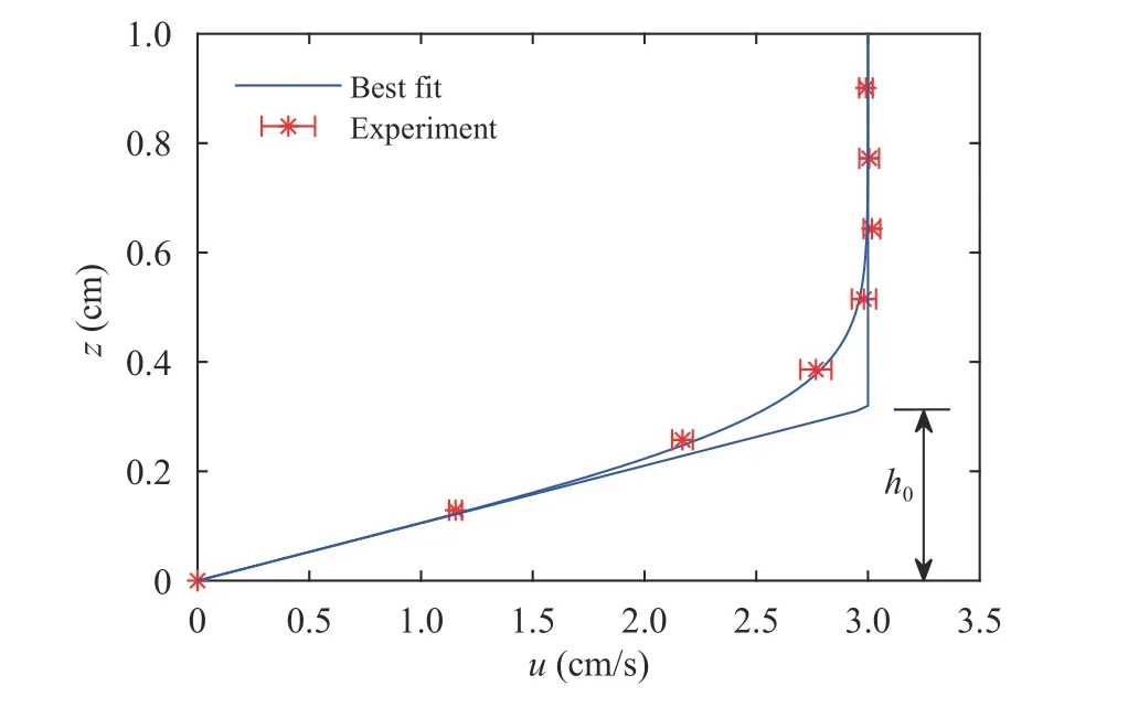
Fig. 4. Boundary layer flow profile at the tip of the salt wedge in Exp.2 exhibiting a shear layer thickness cm
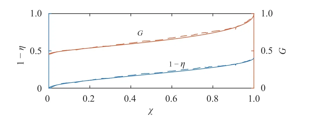
Fig. 5. Variation of nondimensional density interface height and Froude number along the channel in Exp. 2. The dashed and solid lines are experimental measurements and predictions, respectively
where u1=UR/η considering the convective acceleration.fwgradually decreases from 0.011 at the tip to 0.0010 at the exit of the salt wedge. The average friction factor is given by

Following Ref. [19] we use the approximation, η = 1−ηcx/Ls,where ηcis the value at the exit controlto obtain fw≈0.0022. We then estimate the average interfacial friction factor fI≈ 0.011 by applying a least squares best fit to the measured data. Substituting these friction factors into Eqs. (15) and(16), the predicted interface variation is plotted in Fig. 5. The predicted interface length and shape compare well with the measured values. The corresponding composite Froude number (G ) increases from left to right due to the increase of the upper layer fluid velocity by mass conservation in the channel.
In Exp. 2, representative velocity and density profiles at x = 154cm were obtained by simultaneous PIV and LIF measurements as illustrated in Fig. 6. We approximate these profiles with hyperbolic tangent functions. In the stratified flow, the density profile has a density difference of ∆ ρ = ρ2−ρ1, and it changes over a vertical length scale ξ between the two layers.The velocity difference between the two layers is represented by∆u with a shear layer thickness of h. For an arrested salt wedge,we assume the lower layer velocity is zero and h ≪H such that∆u ≈u1.
The displacement between the centre of the shear layer and the density interface is denoted by d. Two important dimensionless parameters are the scale ratio, R = h/ξ; and the asymmetry factor ε = d/(h/2). These characterize the relative thickness of the regions of velocity and density variation, and the magnitude of the profile asymmetry, respectively. The shear layer is much thicker than that of the density layer with a ratio, R = h/ξ ≈ 9,more than sufficient to support Holmboe instabilities [27].
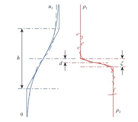
Fig. 6. Profiles illustrating the parameters considered in the velocity and density distributions of an asymmetric stratified shear layer in an arrested salt wedge. The dashed blue line and dashed red line represent the simultaneously measured velocity and density profiles, respectively. The thin solid blue and red lines are the predicted velocity profile and best-fit density profile, respectively. The thick solid lines denote their corresponding piecewise linear profiles
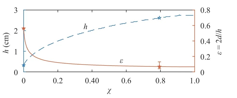
Fig. 7. Spatial variation of the shear layer thickness () and the nondimensional offset () between the centre of the shear layer and the density interface. The stars represent the experimental measurements and lines are based on two-layer hydraulics Eq. (15) and the momentum diffusion Eq. (19)
Once the boundary layer flow reaches the salt wedge and propagates along the density interface, both the shear layer thickness and the offset change (Fig. 7). These variations are calculated using the velocity field obtained by solving Eq. (19) in a Lagragian frame of reference at the density interface predicted from two-layer hydraulics Eq. (15). The boundary layer profile at the tip of the salt wedge is input as the initial condition and k ≈0.5is used by matching the measured shear layer thickness at x = 154 cm, see Fig. 6.
In Fig. 7, the shear layer thickness initially increases quickly as the velocity gradient (∂ u/∂z) is large. As the momentum diffuses, the velocity gradient decreases leading to a slower growth of shear layer thickness. Opposite to the growth of the shear layer thickness, the dimensionless offset ( ε) decreases along the length of the salt wedge. It should be noted that the variation inε shown in the figure is mainly due to the variation of h , sinced ≈0.1 cm along the length of the salt wedge. The dimensionless offset drops sharply at the beginning and then approaches 0.07 near the end of the channel, resulting in a more symmetric flow.
We investigated the 2-D evolution of the velocity and density profiles in an arrested salt wedge. An analytical solution to the two-layer internal hydraulic model considering the interfacial and sidewall friction is derived. The location of the density interface is predicted. The shear profiles are predicted by a momentum diffusion equation following a Lagrangian (moving)frame of reference along the density interface. The predicted density interface agrees well with experiments.
A boundary layer flow enters the salt wedge region resulting in strong asymmetry. The asymmetry, as characterised by the dimensionless offset, decreases from approximately 0.6 near the tip to 0.07 at the exit of the channel. The shear layer increases in thickness due to momentum diffusion. The influence of this spatial variation of the background flow on the interfacial Holmboe instabilities is the subject of ongoing research.
Acknowledgements
This study is supported by the Natural Sciences and the Engineering Research Council (NSERC) of Canada. The authors would like to thank Prof. B.R. Sutherland of University of Alberta,and J. Olsthoorn, D. Robb, K. Everard, and L. Smith of University of British Columbia for helpful discussions.
杂志排行
Theoretical & Applied Mechanics Letters的其它文章
- Crack propagation simulation in brittle elastic materials by a phase field method
- Generalized canonical transformation for second-order Birkhoffian systems on time scales
- Modified slow-fast analysis method for slow-fast dynamical systems with two scales in frequency domain
- Sensitivity analysis of the vane length and passage width for a radial type swirler employed in a triple swirler configuration
- On time independent Schrödinger equations in quantum mechanics by the homotopy analysis method
- Creep relaxation in FGM rotating disc with nonlinear axisymmetric distribution of heterogeneity
