Modeling shale with consideration of bedding planes by cohesive finite element method
2019-12-01ChunfangLiZhennanZhang
Chunfang Li, Zhennan Zhang
School of Naval Architecture, Ocean and Civil Engineering, Shanghai Jiao Tong University, Shanghai 200240, China
Keywords:Shale Bedding plane Cohesive finite element Transverse isotropy Fracture simulation
A B S T R A C T Shale contains distributed directional bedding planes, which make the shale transverse isotropic.To model shale with consideration of the bedding planes, a cohesive finite element method(CFEM) is developed based on the randomized triangular mesh. The interface orientation generated from such mesh tends to be uniformly distributed with the element number increasing.To represent the bedding plane, the interfaces aligned with the bedding plane are assigned the cohesive law that characterizes the bedding plane while the other interfaces are assigned the cohesive law that characterizes the matrix. By this means, the anisotropy characteristics of the stiffness and the strength of shale are well represented. The simulation examples demonstrate that the bedding plane has a significant influence on the fracture trajectory, which is consistent with the observation in the experiment. It is suggested that this modeling method of shale is feasible. It provides an alternative approach to fracture simulation in shale.
The permeability of shale is extremely low. To improve the product of shale gas, the shale reservoir has to be artificially stimulated by fracturing technique. Different from other rocks,the presence of bedding planes makes the shale transverse isotropic, which has a significant influence on the generation of the hydraulic fracture network. The fracturing process of shale involves with the interface debonding and the matrix fracturing.So, the conventional isotropic mechanical model is inadequate to simulate the shale fracture. If the transverse isotropic constitutive model is adopted, the determination of the fracture criterion is another tough problem because the fracture toughness of shale also presents strong directionality. Thus, it is difficult to simulate the shale fracture in the framework of continuum mechanics. Some scholars, e.g. Refs. [1–4], used the discrete element method to simulate the shale fracture. In their method, to simulate the bedding planes in a shale, the distributed parallel smooth joints were embedded into the discrete element model.By this means, the transverse isotropy is well simulated. The discrete element method has many advantages in simulating fracturing process, but it often involves with a lot of degrees of freedom to reasonably simulate a continuous solid.
The typical structural characteristics of shale is that a lot of parallel bedding planes are distributed in it. These bedding planes, acting as interfaces, have lower stiffness and strength than the matrix. Such structural characteristics is similar to the cohesive finite element model (CFEM) proposed by Needleman and co-workers [5–7], in which interfaces are set at the bulk element boundaries. So, the CFEM should provide a feasible approach to modeling shale. In this letter, we develop a modeling method for shale with consideration of the bedding planes in the framework of CFEM.
The basic idea of CFEM is shown in Fig. 1(a). It discretizes an interesting body with triangular elements. The interface is setup at the co-edge of two neighboring elements. The bulk element is characterized by the linear elastic constitutive relation while the interface by the cohesive law (Fig. 1(b)). The cohesive law is a traction-displacement relationship rather than a stress-strain one. The physical meaning of the area enveloped by the cohesive curve is the fracture energy of a material and the peak value is the tensile strength of the material. Hence, the cohesive law contains both the strength and the fracture criterion of material.This makes the CFEM free of choosing the separate fracture criterion. The fracture is only allowed to grow along the interface network. This makes the CFEM free of the mesh modification.Thus, CFEM has been extensively applied to the fracture simulation by far [8]. Based on the similar idea, Mongiza et al. [9] developed the finite element model/discrete element method(FEM/DEM) method, in which a suitable cohesive law for geomaterials is introduced. Yan et al. [10, 11] have used this method to simulate the hydraulic fracturing process of rock.
Modeling idea
In the conventional CFEM, the uniform cohesive law is adopted. So, the simulated body generally presents isotropic. In this letter we find that CFEM has great potential to model the transverse isotropic solid based on the randomized (or unstructured)triangular mesh. The randomized triangular mesh has a distinct characteristics that the orientation of the element edge is randomly distributed. With the element number increasing, the orientation of the element edge tends to be uniformly distributed.To verify this characteristic, we generate a series of randomized triangular meshes by different software. The discretized domain is a square, whose dimension is one meter by one meter. Figure 2(a) shows one mesh with 13476 nodes before inserting interfaces between elements. Figure 2(b) shows the average distribution density of the element edge orientation, which demonstrates that the distribution density is almost a horizontal straight line in between -90° and 90°. This suggests that the distribution of the element edge orientation presents very good uniformity for a randomized triangular mesh. Figure 2(c) shows the distribution density of the element edge orientation with different element number. It is seen that with the element number increasing, the distribution density converges to a constant. This indicates that the element edge orientation tends to be uniformly distributed with the element number increasing.
Since the element edges are uniformly distributed in space,the interface of the CFEM is also uniformly distributed. Thus, we can assign the interface in the bedding direction with different cohesive law to represent the bedding planes. Here, we call such cohesive law as the bedding cohesive law. For the rest interfaces,the cohesive law that characterizes the matrix fracture properties is adopted. We call such cohesive law as the matrix cohesive law. By this method, the transverse isotropy of shale is represented. For the number of interfaces is finite, the interface distribution is discrete. In the practical numerical implementation, we assign the interfaces distributed in a small range of orientation with the bedding cohesive law. For example, the bedding inclination of shale is α. We assign the interfaces (shown in Fig. 2(a))distributed within the range of ( α−dα,α+dα) with the bedding cohesive law. The distribution of bedding interfaces is shown in Fig. 3, which are very similar to the real shale bedding planes shown in Fig. 4. From Fig. 4 it is seen that the real bedding planes are not perfectly continuous while the presented bedding interfaces are also not perfectly continuous. Thus, the designated interfaces in CFEM can represent the bedding planes in geometry at first.
The randomized mesh can be generated via different methods, e.g., the advancing front/layer method [12], the Delaunay triangulation method [13], the “Frontal-Delaunay” method [14],and the Voronoi tessellation [15, 16]. The randomization degree of the mesh is dependent on the concrete generation algorithm,but it should be the common feature that the element edge orientation tends to be uniformly distributed with the element number increasing. For the special case that the bedding plane has strong continuity and directionality, we could adjust the local mesh to make the slightly inclined edges aligned with the bedding plane through the universal mesh technique [17, 18].
Mechanical property representation
Stiffness: One typical feature of a shale is that its stiffness is transverse isotropic. To examine whether this method can represent such property, we adopt the following linear cohesive law.

where σ,τ are the normal and shear traction of interface,respectively; a,s are the normal and shear separation of interface, respectively; kn,ktare the normal and shear stiffness of interface, respectively.
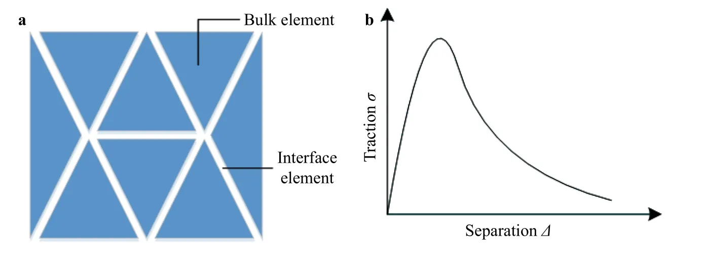
Fig. 1. Modeling method of CFEM. a Discretization of an interesting body; b cohesive law.
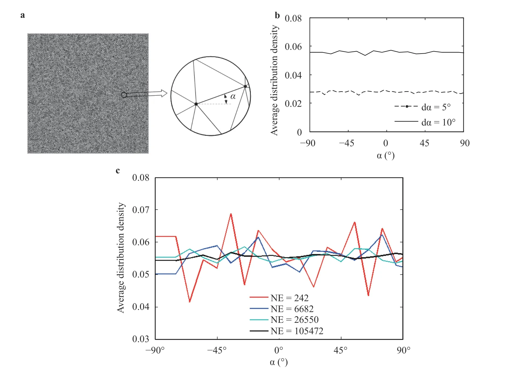
Fig. 2. Distribution of the element edge orientation in the randomized triangular mesh. a Randomized triangular mesh; b distribution density with different angle interval; c distribution density with different element number (NE stands for the element number; the angle interval
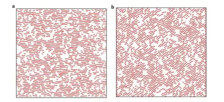
Fig. 3. Distribution of bedding interfaces with the bedding inclination
To represent the transverse isotropy of shale stiffness, we take kn= 796 GPa and kt= 133 GPa for the matrix interface while kn= 318.4 GPa and kt= 53.2 GPa for the bedding interface. The simulation object is a square plate (Fig. 5(a)), whose bottom and left side are normally restricted. The displacement-controlled loading scheme is adopted. The inclination of the prescribed bedding plane is α. The average stress is calculated by the resultant reaction of upper side over the transverse area. The apparent stiffness is calculated by the average stress over the average strain. Gao et al. [19] have conducted a physical test on the stiffness anisotropy. The comparison between the simulated stiffness variation with inclination and the tested results is shown in Fig. 5(b), which demonstrates that the simulated stiffness presents the same trend of the tested ones.
Strength: Another typical feature of shale is that the strength also presents transverse isotropy. To represent the strength property of shale, we define the strength of criterion of an interface as

in which σc,τcare the tensile and the shear strength of an interface, respectively. No matter which one, the normal or the shear traction, reaches the critical value, the interface is transformed into the failed one. For the failed interface, it is reduced to the Goodman joint element which has only the compressive stiffness, no tensile stiffness, with a slight shear stiffness. We simulate the specimen shown in Fig. 5(a) with the strength criteria. For the matrix interface, we take σc= 7.96 MPa,τc= 1.60 MPawhile for the bedding interface we take σc= 3.18 MPa , τc= 0.64 MPa. The simulated strength variation with bedding inclination is shown in Fig. 5(c), which presents the same trend with the tested results reported in Ref. [3].
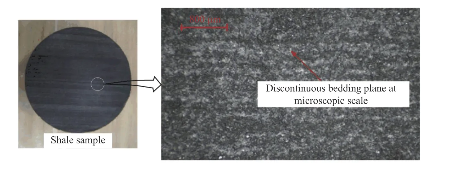
Fig. 4. Sample of real shale (after Ref. [3])
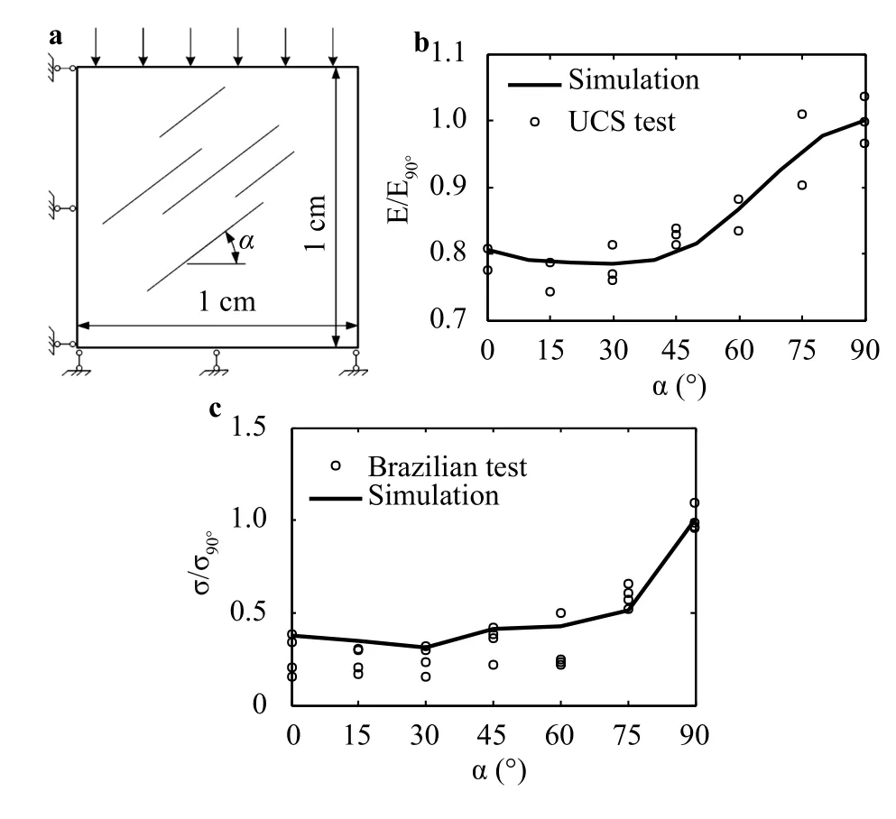
Fig. 5. Mechanical anisotropy represented by CFEM. a Simulation object; b stiffness comparison between the simulated and the tested results reported in Ref. [19]; c strength comparison between the simulated and the tested results reported in Ref. [3]
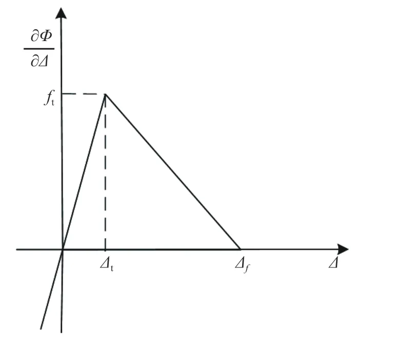
Fig. 6. Diagram of the first derivative of cohesive potential with respect to separation
Impact of bedding plane on fracture process
To examine the impact of the bedding plane on fracture behavior, we adopt the following cohesive law.
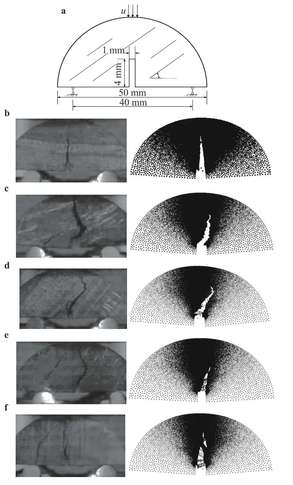
Fig. 7. Impact of bedding plane on fracturing process in the half disc sample a simulation object and the comparison between the tested [20] and the simulated fracture paths with the bedding plane inclination b; c; d; e; f.

where Φ denotes the cohesive potential; ∆ means the total separation,
In the case of interface tension, namely a ≥0, we define the first derivative of cohesive potential with respect to the separation ∆ as

where ftis the tensile strength; ∆tis the interface separation corresponding to the tensile strength; ∆fis the failure separation. The three parameters can be related to macro material parameters by

where Gfis the fracture energy and knis the interface stiffness.
While in the case of interface compression, namely a < 0, we define it as

The diagram of this potential is shown in Fig. 6.
To study the impact of bedding on the fracturing process, we simulate two examples as follows.
Example-1: The simulation object is a half-disc reported in Ref. [20]. Although the disc material in Ref. [20] is coal, not shale,it can clearly demonstrate the impact of bedding planes on fracturing process. Hence, we use this example as reference. The geometry and the boundary condition of this half-disc are shown in Fig. 7(a). A flyer impacts the top of this half-disc with the velocity= −0.0857 m/s. For the matrix interface, we take ft= 5 MPa,∆t= 0.15 µm , ∆f= 15 µm while for the bedding interface we take ft= 1.5 MPa, ∆t= 0.15 µm, ∆f= 15 µm. The simulation results are shown in Fig. 7(b) – 7(f). It is found that when the bedding plane is horizontal (Fig. 7(b)) or vertical (Fig. 7(f)), the fracture advances straightly along the vertical direction. However, in the other bedding plane inclinations, say α = 22.5◦, 45◦, and 67.5◦, the fracture deviates from the vertical direction at first, then turns to the vertical direction. In the case of α = 45◦, the deviation reaches the maximum. The simulated fracture modes generally agree with the observation in Ref. [20].
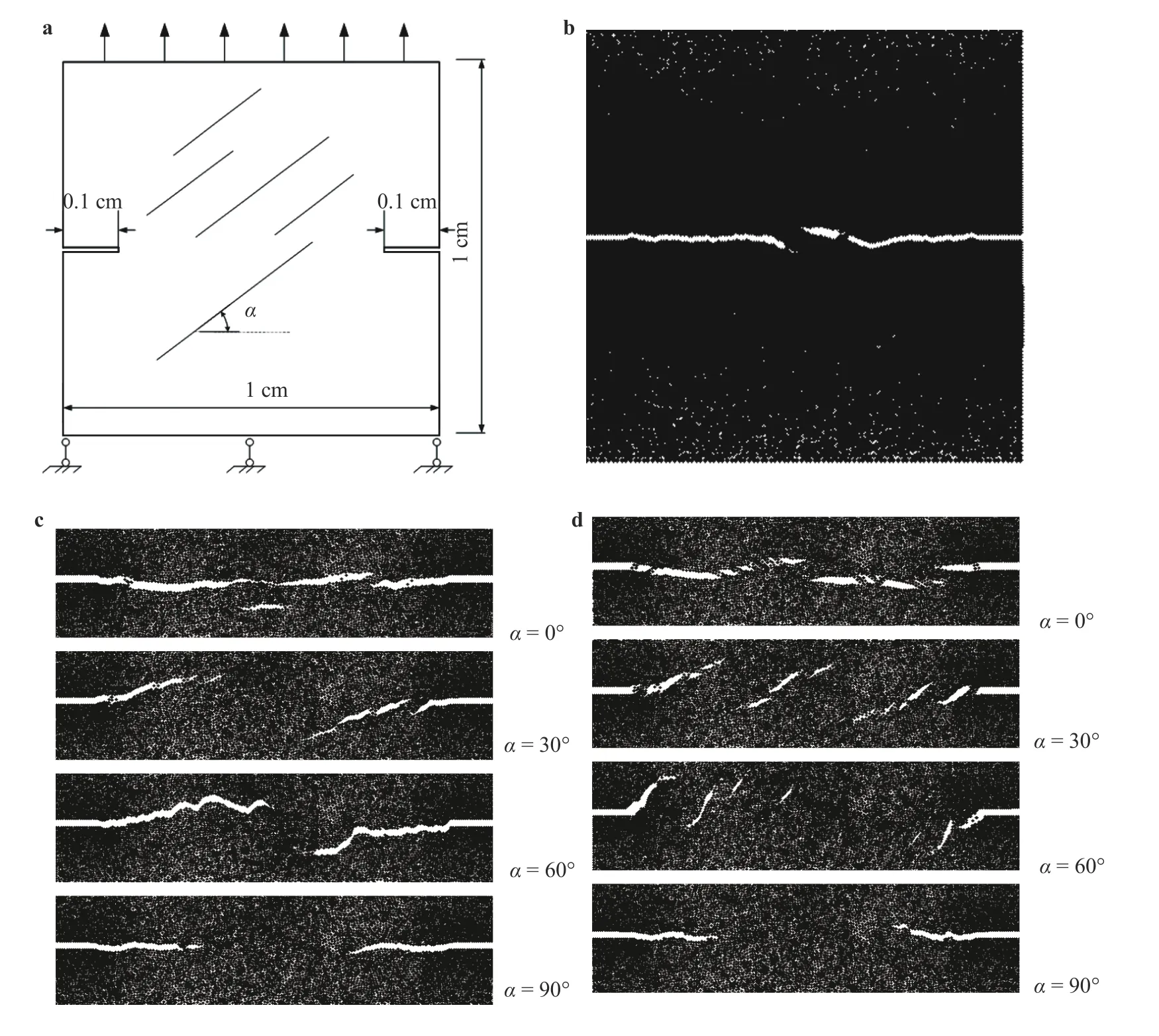
Fig. 8. Impact of bedding plane on fracturing process in uniaxial tension. a Simulation sample; simulated fracture path with b no bedding interfaces; c stronger bedding interface, and d weaker bedding interface .
Example-2: In the second example, we simulate a rectangular sample with two symmetrical notch at the two lateral sides.The geometry of this specimen is shown in Fig. 8(a). It is subjected to the uniaxial tension. The applied strain rate is= 166.67 s−1. For the matrix interface, we take ft= 5 MPa,∆t=0 .15 μm, ∆f=15 μm. To examine the influence of the interface strength on the fracture, we set two cases. One case is with the stronger bedding interface whose parameters are ft= 2.5 MPa, ∆t=0 .15 μm, ∆f=15 μm. Another case is with the weaker bedding interface whose parameters are ft= 0.5 MPa,∆t=0 .15 μm, ∆f=15 μm.
To facilitate identifying the influence of bedding plane, at first we simulate a case without bedding interfaces. The simulation result is shown in Fig. 8(b), which demonstrates that two fractures initiate at the two notches and symmetrically propagate towards each other, normal to the uniaxial tension. This is a typical mode-I fracture growth.
The simulated results with the two kinds of bedding interface are shown in Fig. 8(c) and 8(d), respectively. Compared with the case of no bedding plane (Fig. 8(b)), it is seen that the bedding plane has a significant influence on the fracture trajectory.In the cases of bedding inclination α = 0◦and α = 90◦, the fracture grows straightly, normal to the uniaxial tension. While in the cases of α = 30◦and α = 60◦, the fracture propagates obliquely due to the weak interfaces. Comparing Fig. 8(c) and 8(d), it is found that the weaker the bedding plane is, the more significant the influence of bedding plane is.
As conclusion, the interface orientation generated from a randomized triangular mesh presents a pretty good uniformity,which provides the basis to consider the bedding plane effect in CFEM. By assigning the interfaces aligning the bedding plane with the bedding cohesive law, the transverse isotropy of stiffness and strength of shale can be well represented. By this method, the influence of bedding planes on fracture can be captured.It is suggested the present CFEM method is an effective modeling approach to simulating shale fracture.
Acknowledgment
This work is supported by the National Natural Science Foundation of China (No. 11772190), which is gratefully acknowledged.
杂志排行
Theoretical & Applied Mechanics Letters的其它文章
- Crack propagation simulation in brittle elastic materials by a phase field method
- Generalized canonical transformation for second-order Birkhoffian systems on time scales
- Modified slow-fast analysis method for slow-fast dynamical systems with two scales in frequency domain
- Sensitivity analysis of the vane length and passage width for a radial type swirler employed in a triple swirler configuration
- On time independent Schrödinger equations in quantum mechanics by the homotopy analysis method
- Creep relaxation in FGM rotating disc with nonlinear axisymmetric distribution of heterogeneity
