Dynamic response of clamped sandwich beams: analytical modeling
2019-12-01LangLiBinHanQianChengZhangZhenYuZhaoTianJianLu
Lang Li, Bin Han, Qian-Cheng Zhang, Zhen-Yu Zhao, Tian Jian Lu,*
a State Key Laboratory for Strength and Vibration of Mechanical Structures, Xi'an Jiaotong University, Xi'an 710049, China
b State Key Laboratory of Mechanics and Control of Mechanical Structures, Nanjing University of Aeronautics and Astronautics, Nanjing 210016, China
c School of Mechanical Engineering, Xi'an Jiaotong University, Xi'an 710049, China
d School of Engineering, Brown University, Providence, RI 02912, USA
e Research Institute of Xi'an Jiaotong University, Hangzhou 311215, China
f Key Laboratory of Intense Dynamic Loading and Effect, Xi'an 710024, China
g Nanjing Center for Multifunctional Lightweight Materials and Structures (MLMS), Nanjing University of Aeronautics and Astronautics,Nanjing 210016, China
Keywords:Sandwich beam Cellular core Shock loading Analytical model
A B S T R A C T An improved analytical model is developed to predict the dynamic response of clamped lightweight sandwich beams with cellular cores subjected to shock loading over the entire span.The clamped face sheets are simplified as a single-degree-of-freedom (SDOF) system, and the core is idealized using the rigid-perfectly-plastic-locking (RPPL) model. Reflection of incident shock wave is considered by incorporating the bending/stretching resistance of the front face sheet and compaction of the core. The model is validated with existing analytical predictions and FE simulation results, with good agreement achieved. Compared with existing analytical models, the proposed model exhibits superiority in two aspects: the deformation resistance of front face sheet during shock wave reflection is taken into account; the effect of pulse shape is considered. The practical application range of the proposed model is therefore wider.
Clamped beams are widely found in vehicles and ships. For example, the under-body of a vehicle and the hull of a ship are both comprised of clamped beams. One of the major considerations in clamped beams is their resistance to blast loading in air or underwater. Sandwich beams have been demonstrated to have superior blast resistance compared to monolithic ones [1–5].The benefit primarily comes from the structural responses of sandwich beams that are typically divided into three phases [1],i.e., fluid-structure interaction (FSI) phase, core crushing phase and global deformation phase. At present, each phase can be exploited to further improve and even optimize the blast resistance of the sandwich beam. To this end, analytical models provide the most economical and direct approach.
A variety of analytical models have been developed to not only predict the dynamic response of clamped sandwich beams[6–14] but also determine optimal construction of the sandwich beam, including optimal core compressive strength and optimal mass distribution of front/back face sheets under specific impulse loading. Typically, two groups of existing analytical models are representative. One is the yield locus based model proposed by Fleck and Deshpande [1], and further developed by Tilbrook et al. [6], Qiu et al. [7], Liang et al. [8], and Zhu et al. [9].In this type of model, the final deflection of the back face sheet is determined, but details of core compaction and blast impulse transmission process are neglected, because the core is lumped to add to the face sheets and the blast loading is treated as impulsive. The other group is the one-dimensional (1D) lumped parameter model developed separately by Deshpande and Fleck[10], Main and Gazonas [11], McMeeking et al. [12], and Ghoshal and Mitra [13]. Here, both the blast impulse transmission phase and the core compaction process are well captured, but the final deflection cannot be obtained, because such model considers only a strip through the thickness of the sandwich beam, with the bending/stretching of face sheets and core excluded. Therefore, to provide comprehensive understanding of the dynamic response of clamped sandwich beams, this study aims to develop an improved 1D model by incorporating with the rigid-perfectly-plastic-locking (RPPL) model for core compression and the extended FSI theory of Aleyaasin et al. [14] for shock loading reflection (or, blast impulse transmission) along with the resistance provided by front/back face sheets.
Consider a clamped sandwich beam of span L and unit width, with front face sheet thickness of hf, back face sheet thickness of hband core thickness of l0, as is shown in Fig. 1(a).The face sheets are assumed to be made from a rigid ideallyplastic solid material of yield strength σyand density ρs, while the core is treated as a rigid ideally-plastic foam-like solid with initial density while the core is treated as a rigid ideally-plastic foam-like solid with initial density ρ0. The core compresses at a constant strength σtup to the densification strain of εD, beyond which it becomes rigid, as is shown in Fig. 1(b). This type of constitutive law, known as the RPPL model, is not only representative of high porosity cellular foams, but also other stacked, periodic cellular cores such as prismatic diamond, pyramidal trusses and octet trusses. The tensile strength of the core along beam span direction is also assumed to be constant and equals γ σt,γ being a coefficient ranging from 0 to 1.
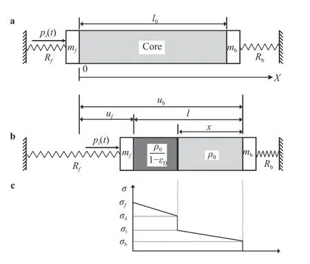
The front and back face sheets of the sandwich beam shown in Fig. 1(a) may be modeled as two clamped monolithic beams loaded with uniform pressure. According to the equivalent method described in the Appendix, the front and back face sheets may be both replaced by equivalent spring-mass systems.As a result, the prototypical problem of Fig. 1(a) is simplified as a 1D double spring-mass model as sketched in Fig. 2. The mass of front face sheet per unit length is mf= ρshfand that of back face sheet is mb= ρshb, in which mfand mbare actually the areal densities of the front and back face sheets.
Based on the above simplified model, governing equations for each part of the sandwich beam are derived. Upon neglecting elastic wave propagation in the core, two distinct cases are considered: (1) shock wave propagates in the core; (2) no shock wave propagates in the core.
(1) Shock wave propagating in sandwich core: motion equations
When an incident air blast pi(t) with reflected over-pressure pr(t)impinges on the front face sheet, the front face sheet is accelerated and the core is compressed. It is assumed that the core strength is high enough to push the back face sheet to move,provided that a shock wave front is initiated in the core and propagates from the front to the back face sheet. According to the simplified model of Fig. 2, the compacted core moves as a rigid body with equal velocity of the front face sheet, while the uncompressed core moves as a rigid body with equal velocity of the back face sheet.
From the dynamic equation of motion of the equivalent single-degree-of-freedom (SDOF) system (Appendix, Eq. (A1))for the front face sheet, it follows that

where σf(t) denotes the contact stress at the interface between the core and the front face sheet, ufis the location of the front face sheet, and Rfdenotes the resistance of the front face sheet given by Eq. (A2).
Similarly, for the back face sheet

where σb(t) denotes the contact stress at the interface between the core and the back face sheet, ubis the location of the back face sheet, and Rbdenotes the bending/stretching resistance of the back face sheet.
With εDas the densification strain, the conservation of mass dictates that the density of the densified core material is ρ0/(1−εD), and hence the total thickness of the core (l = ub−uf)can be rewritten as

where x denotes the thickness of the uncompressed core.Therefore, the motion equation for the compressed core,obeying Newton's second law, is given by


Fig. 1. a Schematic of clamped sandwich beam subjected to air-blast loading and b engineering stress versus strain relationship (---) for cellular material and RPPL idealization (−).

Fig. 2. Deformation process of clamped sandwich beam under airblast loading at a t = 0 and b t > 0. For b, the variation of stress within sandwich core along its thickness direction is shown in c.
where σd(t) is the stress behind the shock front and Rc1is the bending/stretching resistance of the compressed part of the core. It is noticed that the stress ahead of the shock front equals the quasi-static compressive strength of the core. The motion equation for the uncompressed core, obeying Newton’s second law, is

where Rc1is the bending/stretching resistance of the uncompressed part of the core.
In addition, momentum conversation across the shock front sheets leads to

Substituting Eqs. (3), (4), and (6) into Eq. (1), and Eqs. (3), (5)into Eq. (2), yields the set of nonlinear ordinary differential equations

which can be integrated numerically with initial conditions

(2) No shock wave propagating in sandwich core: motion equations
The nonlinear ordinary differential equations of Eq. (7) are valid only when the shock front is initiated and propagates within the core. These equations are nonetheless meaningless in two scenarios. Case a: at the beginning, core compaction cannot be initiated by the front face sheet. Case b: during compression, the core can no longer be compacted.Case a:
In this case, the front face sheet, the back face sheet and the core move as an entirety. Correspondingly, the governing equations for the entirety of the sandwich beam are given as

for which the initial conditions are given by Eq. (8).
The boundary condition that distinguishes whether the compaction of the core can be initiated or not depends on the peak pressure of the reflected over-pressure and the compressive core strength. When the core cannot be compacted, the sandwich beam is accelerated as an entirety and the acceleration of its front face sheet is obtained from Eq. (9), as

To initiate the shock front, the acceleration of the front face sheetappearing in Eq. (1) should satisfy the conditionnamely

where σf(0)= σtat t = 0.Case b:
In this case, as the cellular core cannot be compacted at a specific time teq, two situations may arise. One is that the core is yet fully densified (partial densification), and the other is that the core is fully densified (full densification). For the former, the front and back face sheets attain equal velocity temperately at teq.For the latter, the front face sheet slams into the back face sheet at teq, and then the two obtain equal velocity at time teq′due to momentum conservation, with ∆ t = teq′−teqrepresenting the duration of slamming (collision). Correspondingly, the momentum conservation equation is


Rewriting Eqs. (13) and (14) in standard form yields the following nonlinear ordinary differential equations

which can be integrated numerically with initial conditions

for partial densification and

for fully densification.
For each case considered, the dynamic response of the clamped sandwich beam under blast loading can be predicted by solving the corresponding nonlinear ordinary differential equations. Table 1 summarizes the equations needed to be solved for different cases. Note that the equations derived hitherto are based upon the reflected pressure pr(t) of a specified air-blast. In reality, the reflection process is coupled with the motion of front face sheet. To build the governing equations based upon the incident pressure pi(t) of a specified air-blast,the relationship between pi(t) and pr(t) should be established,as done below.
Following Taylor [15], the incident air-blast pulse in free air is defined as

where t0is the decay period of incident pulse and p0is the peak pressure. As soon as an incident air-blast pulse impinges on the front face sheet of sandwich beam, the blast pulse is reflected and amplified, with the amplification factor defined as

where pA= 1 bar is the ambient pressure. For small values ofwhile, for, CR→8 [15].
The reflected over-pressure is dependent upon both the incident pressure and the moving velocity of face sheet. According to the extended Taylor theory [14], the reflected pressure can be expressed as


Table 1 Governing equations and initial conditions for different cases considered.


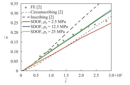
Fig. 3. Normalized mid-span deflection () plotted as a function of normalized impulse (): comparison between FE simulation results [2] and analytical predictions by the present model as well as the yield-locus based model [2].
Figure 3 plots the normalized mid-span deflection of back face sheet as a function of normalized impulse: the present analytical predictions are compared with the FE simulation results and analytical model predictions of Qiu et al. [2]. The present model predictions are in good agreement with existing FE results and lie within the upper and lower bounds of the predictions obtained with the yield-locus based model when the pressure pulse is sharp ( p0= 12.5 MPa or 25 MPa). For the case of p0= 2.5MPa, however, analytical predictions of the present model are lower than the FE results, which may be attributed to the influence of pulse shape. When the pressure pulse is sharp, it can be treated as an impulse, leading to the good agreement between the present model and the yield-locus based model. On the contrary, when the pressure pulse is flat, the pulse shape effect becomes significant, and treating the pressure pulse as an impulse may overestimate the impulse transmitted to the front face sheet, thus causing the overestimation of mid-span deflection. Consequently, for the case when the pulse shape effect becomes important, the yield-locus based model is no longer applicable, but the present model is still valid because the incident loading considered is a pressure-time history which has already included the influence of pulse shape.
In summary, different from existing analytical models, the model proposed in the present study takes into account both the bending/stretching resistance provided by the face sheets and the effect of pulse shape in the FSI process, thus more universally applicable.
Acknowledgments
This work was supported by the National Natural Science Foundation of China (Grants 11972185, 11802221, 11472208, and 11472209), the China Postdoctoral Science Foundation (Grant 2016M600782), the Postdoctoral Scientific Research Project of Shaanxi Province (Grant 2016BSHYDZZ18), the Zhejiang Provincial Natural Science Foundation of China (Grant LGG18A020001), and the Natural Science Basic Research Plan in Shaanxi Province of China (Grant 2018JQ1078).
Appendix: the rigid perfectly plastic SDOF model
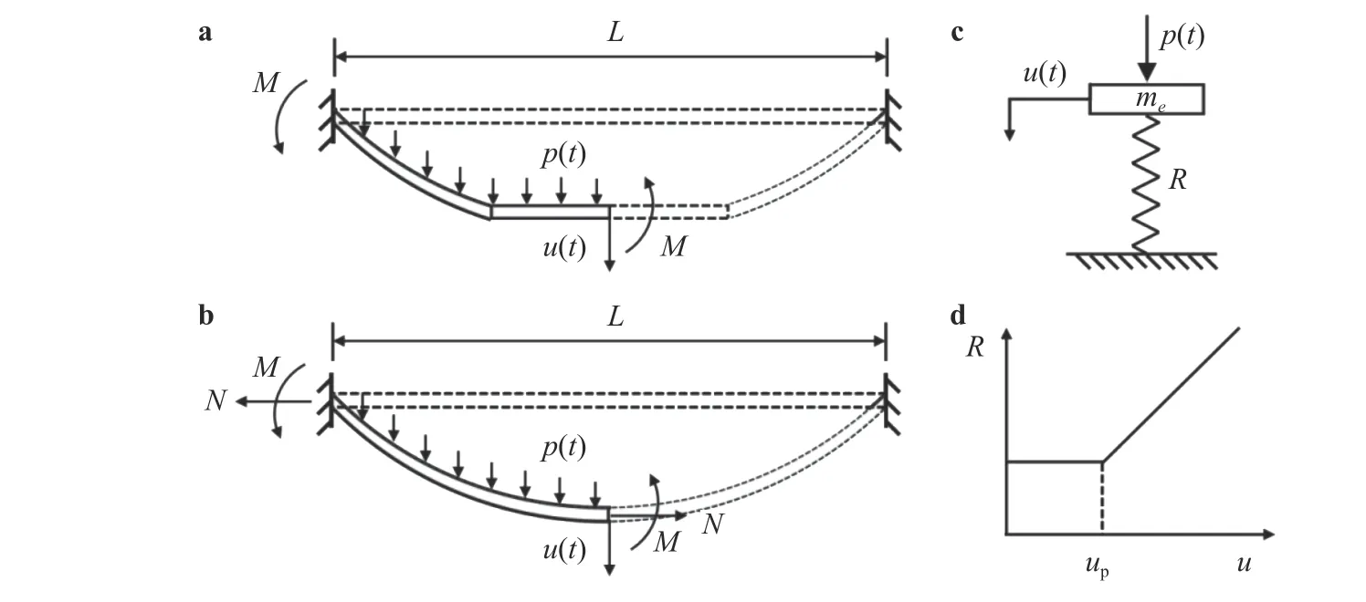
This Appendix provides the derivation of the rigid perfectly plastic SDOF model. For an ideally rigid plastic monolithic beam of mass per unit length m , clamped at both ends and loaded with transverse pressure p (t), its transverse motion can be separated into two sequential phases, as is shown in Fig. A1. Phase I starts from the formation of plastic hinges at the clamped ends and continues until the two traveling hinges meet at the midspan of the beam. The subsequent phase II is dominated by axial stretching with stationary plastic hinges existing at the mid-span and at the clamped ends, known as the catenary response [17].
As an equivalent SDOF model, the clamped monolithic beam is transformed to an equivalent spring-mass system, where the displacement and velocity of the mass equal to those of the beam according to the energy equivalence between the beam and the equivalent system [18, 19] (Fig. A1(c)). The resistancedeflection curve covering both phases I and II is displayed in Fig.A1(d), in which upseparates the two phases.
With reference to Fig. A1(c), the dynamic equation of motion for the equivalent SDOF system can be written as

where u (t) is the equivalent deflection of the mass,is the equivalent mass acceleration, and R (u) and KLMare the beam resistance and the so-called load-mass factor, respectively. For a fully clamped beam with uniformly distributed mass and load,KLM= 0.66 [18] and the resistant function R (u) is given by

where up(equaling to 2 M/N) denotes the transverse deflection at the end of phase I, M = σ0h2/4 is the plastic bending moment within the span and at the clamped ends, and N = σ0h is the longitudinal plastic stretching strength where h and σ0denote the thickness and yield strength of the beam, respectively.
The cellular core (with densification strain εD) of a sandwich beam may be taken as a compressed beam. Let the thickness of the clamped beam be denoted by l and the thickness of the uncompressed part be denoted by x. The bending moment and stretching strength of the compressed part are then given by M = γσt(l −x)2/4 and Nc= γσt(l −x)/(1−εD). Similarly, for the uncompressed part,M = γσtx2/4 and Nc= γσtx.
Nomenclature
L span of sandwich beam
hf, hbthickness of front/back face sheet
l0, l , x initial thickness of core, current thickness of core, and thickness of uncompressed core
σyyield stress of face sheet material
ρsdensity of face sheet material
ρ0density of core material

Fig. A1. Modified equivalent SDOF system: a deformation profile of real beam in phase I, b deformation profile of real beam in phase II,c equivalent spring-mass system, and d typical resistance-deflection curve of the equivalent system
σtcrushing stress of core material
εDdensification strain of core material
γ, KLMcoefficient ratios defined in the paper
mf, mbmass of front/back face sheet per unit length
pi(t), pr(t) incident/reflected pressure
σf(t), σb(t) contact stress between core and front/back face sheet
σd(t) stress behind shock front
Rf, Rbbending/stretching resistance of front/back face sheet
uf, ublocation of front/back face sheet
Rc1, Rc2bending/stretching resistance of compressed/uncompressed core
pA, p0ambient pressure and peak pressure of incident shock load
CRamplification factor of reflected pressure
teq, t′eqinstant when front and back face sheets attain equal velocity
∆t duration of collision
杂志排行
Theoretical & Applied Mechanics Letters的其它文章
- Crack propagation simulation in brittle elastic materials by a phase field method
- Generalized canonical transformation for second-order Birkhoffian systems on time scales
- Modified slow-fast analysis method for slow-fast dynamical systems with two scales in frequency domain
- Sensitivity analysis of the vane length and passage width for a radial type swirler employed in a triple swirler configuration
- On time independent Schrödinger equations in quantum mechanics by the homotopy analysis method
- Creep relaxation in FGM rotating disc with nonlinear axisymmetric distribution of heterogeneity
