Mathematical Model and Machining Method for Spiral Flute Rake Faces of Hourglass Worm Gear Hob
2019-08-01YANGJieLIHaitaoRUIChengjieHUANGYiZHANGXiaodi
YANG Jie,LI Haitao,2*,RUI Chengjie,HUANG Yi,ZHANG Xiaodi
1.College of Engineering,China Agricultural University,Beijing 100083,P.R.China;
2.Key Laboratory of Optimal Design of Modern Agricultural Equipment in Beijing,China Agricultural University,Beijing 100083,P.R.China;
3.Beijing Kuiente Technology Co,Ltd,Beijing 100043,P.R.China
Abstract: To improve the cutting performance of an hourglass worm gear hob and the accuracy of the resulting worm gear,the rake angles of the teeth on the pitch circle should be reduced. A method of forming the spiral flutes by using a variable transmission ratio was developed. This method ensures that the rake angles on the indexing torus of each tooth are approximately 0° . Based on the gear meshing theory and the hourglass worm forming method,the discretization mathematical model of the rake face of a planar double-enveloping worm gear hob was established by using cylindrical generating surface,and the feed parameters for machining the rake face for a variable transmission ratio were obtained. The spiral flute was simulated and the hob was machined on a four-axis CNC milling machine. A contourgraph was used to measure the rake angle. The measurement results showed that the proposed method can reduce the absolute value of the rake angle on both sides of the cutting teeth,which can be used for machining the spiral flute rake face of an hourglass worm gear hob.
Key words: hourglass worm gear hob;cylindrical generating surface;spiral flute;rake face;rake angle
0 Introduction
Compared with cylindrical worm gear drives,hourglass worm gear drives are smaller and has a greater load capacity,and higher transmission efficiency[1-3]. The accuracy of the worm gear tooth surfaces depends on the performance of the worm gear hob used to machine the worm gear[4-5]. Chang et al.[6]developed a general mathematical model for gears manufactured with computer numberical control(CNC)hobbing machines. Geometry errors in hob cutters are one of the most important factors influencing the quality of the machined gears. Liston[7]investigated gear geometry errors due to sharpening errors in the hob cutter. Winter and Wilkesmann[8],Simon[9],Bosch[10]and Bär[11]proposed various methods of obtaining more accurate worm gear surfaces. Kin[12]studied the variations in worm gear tooth surfaces due to deviations in the cutting edges of hob cutters. To the knowledge of the authors,investigation into the milling profiles of hob cutters with helix gashes has not been addressed.
The type of flutes on the hob affects the shape of the cutting edge and determines the rake angles on both sides of the cutting teeth,which affects the accuracy of the worm gear that the hob produces and the machining efficiency. With straight flutes,one side of the cutting teeth has a positive rake angle and the other has a negative rake angle. Large negative rake angles can cause problems in machining.These factors reduce the worm gear tooth surface accuracy. Large positive rake angles result in faster tooth wear,i.e.,a reduced service life of the hob.Therefore,the hob is usually designed with spiral flutes shaped to ensure that the rake angles on both sides of the teeth are approximately zero.
Dong[13]and Liu[14]developed a mathematical model for worm gear hobs with straight flutes. If the spiral angles are small,straight flutes are used because the resulting negative rake angles on one side of the cutting teeth do not significantly affect cutting. However,spiral flutes are used for hobs with multiple threads because with straight flutes,the magnitudes of the negative rake angles on one side of the cutting teeth are sufficiently large that the cutting edges are not effective[15-19]. Chang[20]developed a general mathematical model of the helix gash of a hob cutter and studied the errors between the actual machined surface and the mathematical rake surface that are caused by the movement of the cylindrical surface. Liu et al.[21]analyzed the orthogonal curve of the spiral line of Hindley worm gears. The transmission ratio of the orthogonal curve of the worm gear was derived,but a mathematical expression for this orthogonal curve was not provided. Liu[22]studied the forming of the spiral flutes in gear hobs using a grinding process. It is difficult to determine the geometry of the spiral flutes in worm gear hobs because the shape and angle of the cutting edges on an hourglass worm gear hob are different. Furthermore,it is difficult to ensure that the rake angles on the right and the left edges of the teeth are near zero[1,19].
In this paper,we propose a method for generating spiral flutes in an hourglass worm gear hob. An expression for the transmission ratio for generating the spiral flutes using a cylindrical generating surface is derived. The mathematical model of the spiral flute rack faces is obtained. The software VERICUT is used to simulate the machining of the spiral flutes of a hob. The rake angles on both sides of the teeth of the simulated workpiece are calculated,and these values are compared with those obtained from the equations to validate the mathematical model and the design method.
1 Mathematical Model of Spiral Flute Rake Faces
As shown in Fig.1,the plane Σdof the grinding wheel forms the spiral groove surface Σ1in a planar double-enveloping hourglass worm. The surface Σ1is the initial surface for a worm gear hob,which is used to cut a worm gear tooth surface,where the worm gear and a matching hourglass worm are a planar double-enveloping worm pairs. The spiral surface Σ1is referred to as the basic worm of the hob.

Fig.1 Forming the basic worm using a flat grinding wheel
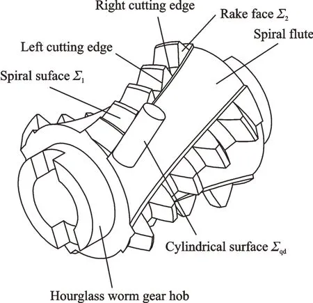
Fig.2 Forming the spiral flutes using a cylindrical surface
As shown in Fig.2,a cylindrical surface Σqdis the envelope for forming the spiral flutes that are cut into the basic worm of the hob,creating the tooth rake faces Σ2. The intersection lines of the spiral surface Σ1of the basic hob worm and the rake faces Σ2are created by cutting the spiral flutes form the cutting edges of the hob teeth. The method used to form the rake faces Σ2of the spiral flutes affects the geometry of the edges,which determines the rake angles on the left and the right sides of the cutting teeth. The machining efficiency and the accuracy of the worm gear depend on the rake angles of the teeth.
1.1 Coordinate systems for a plane Σd envelope of spiral surface Σ1
It is assumed that the spiral surface of the basic hob worm is ground with a flat grinding wheel. A right-handed Cartesian coordinate system σ1,as illustrated in Fig.3,is defined. Two static coordinate systems σoi(Ooi;ioi,joi,koi)(i=1,2)are introduced,where the subscript“1”indicates the frame fixed to the worm and the subscript“2”indicates the frame fixed to the worm gear. The dimension a= |O1O2| is the center distance between the worm and the worm gear.
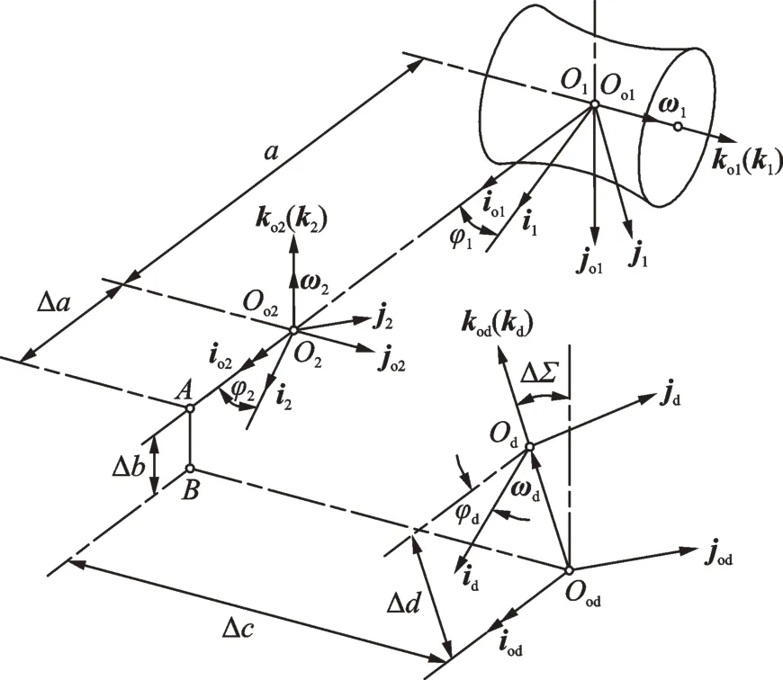
Fig.3 Coordinate systems of the basic hob worm and the grinding head
Two moving coordinate systems σi(Oi;ii,ji,ki)(i=1,2)are defined,where subscript i means the same as defined above 1 is fixed to the worm and 2 is fixed to the worm gear. The instantaneous angular position of the worm is φ1,the instantaneous angular position of the worm gear is φ2=i21φ1,here i21is the ratio of the worm and the worm gear. The initial positions of the worm and the worm gear are φ1=φ2=0°.
A static coordinate system σod(Ood;iod,jod,kod)is fixed to the base. A moving coordinate system σd(Od;id,jd,kd)is fixed to the grinding head holder. When grinding the spiral surface of the basic hob worm,the workpiece(i.e.,worm blank)rotates with a speed ω1about the axis ko1,and the instantaneous angular position is φ1=|ω1|∙Δt. The rotational speed of the grinding head holder about the kodaxis is ωd,the angular position is φd=|ωd|∙Δt,and the initial positions of the worm blank and the grinding head holder are φ1=φ2=0°.
The instantaneous angular position φ1of the worm blank is proportional to the instantaneous angular position φdof the grinding head holder,that is,φ1=i1dφd,where i1dis the speed ratio of the worm blank and the grinding head holder.
Worm drives produced with current methods do not mesh well. This problem can be addressed by modification. The worm surface can be modified by changing the relative position and motion of the grinding head holder and the worm blank. Specifically,the following relations should be satisfied:Δb=Δc= Δd=0,ΔΣ =0,Δa>0,and Δi= i1d-i12,where Δa is the center distance correction,Δb the correction perpendicular to the axis of the worm,Δc the correction along the axis of the worm,Δd the displacement along the axis of the grinding head holder,ΔΣ the angle correction,Δi the transmission ratio correction,i1dthe speed ratio of the worm blank and the grinding head holder,and i12the transmission ratio of the worm pair[1].
The equations describing the spiral surface of the basic hob worm in the coordinate system σ1are as follows

where(x1,y1,z1)is an arbitrary point on the spiral surface in the coordinate system σ1;(r1)1the coordinates of a point;(vd1)1the relative speed between a point on the cutting plane and a point on the basic hob worm;and(n1)1the unit normal vector of an arbitrary point on the spiral surface of the basic hob worm[1,13-14].
1.2 Coordinate systems for cylindrical surface Σqd envelope of spiral flute rack face Σ2
The rake faces of the hourglass worm gear hob are formed by cutting the spiral flutes. The flutes are cut using a cylindrical cutter. A right-handed Cartesian coordinate system is defined as illustrated in Fig.4. A static coordinate system σqo1(Oqo1;iqo1,jqo1,kqo1)is fixed to the base. A moving coordinate system σq1(Oq1;iq1,jq1,kq1)is fixed to the basic hob worm,where Oqo1is the origin of the coordinate system,Oqo1coincides with Oq1,and kqo1=kq1coincides with the rotational axis of the basic hob worm.

Fig.4 Coordinate systems for rake face machining
A static coordinate system σqod(Oqod;iqod,jqod,kqod)is fixed to the base,where iqod=iqo1and kqod=-jqo1. A moving coordinate system σqd(Oqd;iqd,jqd,kqd)is fixed to the tool holder,where iqd=iqod,kqdcoincides with the tool holder axis. Zqoddenotes the distance from the tool holder axis Oqdto point A,and the dimension aq=|OqodOqo1| is the distance between the origins of the two coordinate systems.The point Oqodand the rotational axis of the basic hob worm lie in the plane S.
The instantaneous velocities of the tool holder in the iqodand jqodaxes are vxand vy,respectively,and the displacements arerespectively,where the displacements satisfy the relation Xqod=The changes in the displacement along the two axes are
The instantaneous rotational speed of the basic hob worm about the kqo1axis is ωq1,the angular position of the hob worm isand the change in the angular position is dφq1=|ωq1|dt. The initial position is Zi=0,φq1(0)=φh,Yqod(0)=0,Xqod(0)=r2,where φhis the angular position of the worm blank when the throat of the basic worm rotates into the plane S.
The instantaneous rotational speed ωq1of the basic hob worm about the kqo1axis is proportional to the instantaneous velocity vyof the tool holder along the jqodaxis,i.e.

where iqd1is the ratio of the basic hob worm rotation and the cylindrical surface movement,which is referred to as the transmission ratio.
1.3 Transmission ratio iqd1
The variable transmission ratio iqd1is obtained as follows[23-26]

If Zi= 0,φd= α;thus,the transmission ratio is fixed and can be obtained as follows

1.4 Geometry and normal vector of cylindrical cutter
Fig.5 shows the cylindrical surface that generates the spiral flutes. The equation of the cylinder Σqdin the moving coordinate system σqdis


Fig.5 Cylindrical generating surface
The equation of the cylinder Σqdin the static coordinate system σqodis

where the position of Oqdrelative to Oqodis determined as follows

The equation of the cylinder Σqdin the static coordinate system σq1is

where(Oqo1Oqod)qo1is the distance between the origins of the two coordinate systems,i.e.,(Oqo1Oqod)qo1=aq.
The position of an arbitrary point on the rake face in the coordinate system σq1is

where rxis the radius of the cylindrical cutter and the parameters of the cylindrical generating surface are θ and h,which are both positive,i.e.,θ ≥0 and h ≥0.
The unit normal vector of the cylindrical generating surface is(nqd)qdin the σqdcoordinate system and(nqd)q1in the σq1coordinate system. Eq.(11)shows the relation between (nqd)qdand (nqd)q1through a coordinate transformation

The orientation of(nqd)qdis outward from the rake face.
In the σq1coordinate system,(nq1)q1is the unit normal vector of an arbitrary point on the rake face,where

The expression for the unit normal vector of an arbitrary point on a rake face in the coordinate system σqodis

1.5 Conjugate equation of the first envelope
In the σqodcoordinate system,at the contact point,the relative speed between the cylindrical generating surface and the rake face is(Vqd1)qod. The conjugate equation of the first envelope is obtained from gear theory[23-26].

where

The rotational speed of the basic hob worm in the σq1coordinate system is(ωq1)q1,which can be expressed as

The rotational speed of the basic hob worm in the σqo1coordinate system is(ωq1)qo1,which can be expressed as

The rotational speed of the basic hob worm in the σqodcoordinate system is(ωq1)qod,which can be expressed as

The relative rotational speed of the basic hob worm and the cylindrical surface in the σqodcoordinate system is(ωqd1)qod,which can be expressed as

The cylindrical surface does not rotate,thus the rotational speed of the cutter(ωqd)qodis zero.
Substituting Eq.(19) and (ωqd)qod=0 into Eq.(20),the relative rotational speed is obtained

The relative linear velocity of the basic hob worm and the cylindrical surface in the σqodcoordinate system is(vqd1)qod,which can be expressed as

The linear velocity of the cylindrical surface in the σqodcoordinate system is(vqd)qod,which can be expressed as

The basic hob worm has no translational motion,thus the linear velocity(vq1)qodis zero.
Substituting Eq.(23) and (vq1)qod=0 into Eq.(22),the relative linear velocity is obtained

Substituting Eqs.(6),(16),(19),(21),and(24)into Eq.(15),the relative speed between the cylindrical generating surface and the rake face is obtained

Substituting Eqs.(13)and(25)into Eq.(14),the following expression is obtained

Substituting Eq.(2)into Eq.(26),the following expression is obtained

The conjugate equation of the first envelope is

1.6 Equation for rake face
Eqs.(9)and(28)can define the rake face

The following expression is obtained from Eq.(2)

Since vyand ωq1are unknown, Yqod=cannot be determined using the Newton-Leibniz formula. Thus,Yqodis discretized to obtain the relative motion for machining the spiral flutes using a variable transmission ratio.
If Ziis an integer,at the axial coordinate Ziof the basic hob worm(-0.5Lw≤Zi≤0.5Lw),the following expression is obtained

The equations describing the machine motion for cutting the spiral flutes using a variable transmission ratio are

The equations describing the machine motion for cutting the spiral flutes using a fixed transmission ratio are

2 Calculation and Analysis of Hob Rake Angle
From Eqs.(1)and(29),equations describing the edge geometry of the hob can be obtained. As shown in Fig.6,the normal vector on the rake face and on the spiral surface are obtained at an arbitrary point on the edges of the hob,and the rake angles[27]are obtained as follows

where Wq=arccos[(nq1)1∙(n1)1]is the angle between the normal vectors of the rake face and the spiral surface. The expression of(nq1)1,(n1)1and(nd)dare as follows

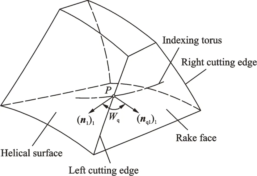
Fig.6 Angle between tooth surfaces at a point on tooth cutting edge

The angles were calculated for an example hob,where the parameters for the example are given in Table 1. The rake angle of each tooth on the pitch circle was obtained for both fixed and variable transmission ratios. The rake angle results are shown in Tables 2,3.

Table 1 Parameters for an example planar double-enveloping hourglass worm gear hob

Table 2 Hob tooth rake angles on the pitch circle obtained using a fixed transmission ratio

Table 3 Hob tooth rake angles on the pitch circle obtained using a variable transmission ratio
The rake angles on the pitch circle obtained using a fixed transmission ratio and a variable transmission ratio are plotted in Fig.7.
(1)As shown in Table 2,when the spiral flutes are machined using a fixed transmission ratio,the left- and the right-side rake angles of the hob teeth vary between ±5.4°. The rake angles on the right side are negative. As shown in Fig.7,the absolute values of the rake angles from the exit(position Zi=-0.5Lw)to the inlet(position Zi=0.5Lw)of the hob initially decrease but then increase. The magnitudes of the rake angles on the throat teeth are minimal.
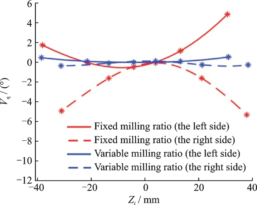
Fig.7 Hob tooth rake angle vs. axial position for fixed and variable transmission ratios
(2)As shown in Table 3,when the spiral flutes are machined using a variable transmission ratio,the left- and the right-side rake angles of the hob are between ±0.52°. Compared with fixed transmission ratio,use variable transmission ratio to form the spiral flutes,the rake angles on both sides of the hob tooth are much smaller. As shown in Fig.7,the right- and left-side rake angles are both approximately zero. The cutting performance on both sides of the teeth will be significantly improved.
3 Simulation of Spiral Flute Forming
The machining of the example hob with four threads,shown in Table 1,was simulated using the software VERICUT. In the simulation,a four-axis CNC machine with a B axis,a C axis,an X axis,and a Z axis was assumed[28-29].
The simulation parameters for the first spiral flute are shown in Table 4. The parameters for the X and Z axes were held constant,and the parameters for the C axis were given as 90°,180°,270° to generate the second,the third,and the fourth spiral flutes,respectively.
The simulated machined surfaces of the basic hob worm and the final hob with spiral flutes are shown in Fig.8.
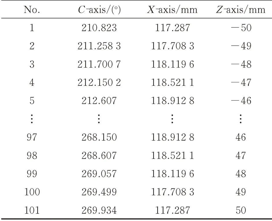
Table 4 Machine motion parameters for machining spiral flutes using a variable transmission ratio
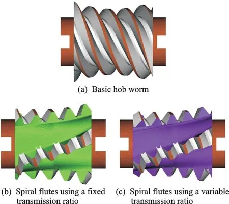
Fig.8 Simulation results
The geometry of the final hob surface was used to obtain the angle Wqbetween the normal vectors of the rake face and the spiral surface,as show in Fig.9. The rake angle Vqon both sides of the teeth was obtained using the formula Vq=Wq-90°,and the results are shown in Table 5.
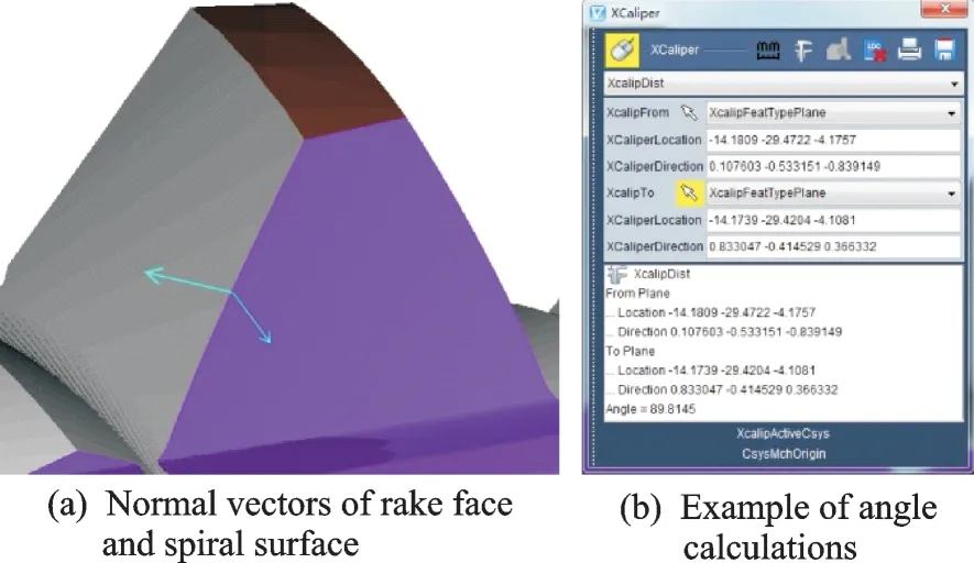
Fig.9 Angles of the final tooth surfaces

Table 5 Rake angles on pitch circle for teeth machined with a variable transmission ratio
The measurement results in Table 5 show that the method can reduce the absolute value of the rake angles on both sides of the hob,and the rake angles are between -0.4°and 0.3°.
4 Experiments and Measurements
The hob machining experiment was conducted on a CNC milling machine with A,X,Y,Z fouraxis linkage. The model of the machine tool was Beijing Jingdiao JDVT700T-A13S. The A-axis of the machine tool was the rotational movement axis,and the X,Y,and Z axes were the linear movement axes. The parameters of the experimental hob were the same as Table 1. The hourglass worm gear hob machining experiment is shown in Fig.10.

Fig.10 Hourglass worm gear hob machining experiment
One row of teeth on the hourglass worm gear hob was cut and number of teeth was counted after cutting,as shown in Fig.11.

Fig.11 Single tooth and its number
The rake angle of each tooth was measured using an S neox contourgraph. The measurement accuracy of optical profiler was 0.1 μm. The Nikon DI 20X objective was used,the scanning area resolution was 1 360 px×1 024 px,and the scanning range was T=10 μm,B=30 μm. In the“Confocal”mode,contour data were collected on the measured point on the cutting edge and the measured data was saved as“*.plux”file using the SensoSCAN menu. The data acquisition process is shown in Fig.12.

Fig.12 Collect data of the point being measured
We loaded the“*.plux”file data measured by Sneox into SensoPRO to analyze the measurement.As shown in Fig.13(a),the measurement data of the rake face and the spiral face and the cutting edge of the cutting teeth were imported into SensoPRO.As shown in Fig.13(b),the cutting edge was rotated to a vertical position for easy measurement. As shown in Fig.13(c),two planes near the cutting edge were selected and the angle between the two planes were measured. The results of the measurements are shown in Table 6.

Fig.13 Analysis and measurement of angles

Table 6 Rake angles measured by contourgraph
It can be seen from Table 6 that the absolute value of the rake angles on both sides of each tooth is small,and the maximum is the right side rake angle of the tooth No.1,the value is -0.409 7°,and the minimum is the left side rake angle of the tooth No.5,which is -0.084 8°. Compared with Table 3,the measurement results are biased. The maximum error is the left side rake angle of the tooth No.5,which is 0.495 92°;and the minimum error is the right side rake angle of the tooth No.1,which is 0.031 06°. The error is caused by the selected position of the two measurement planes.
5 Conclusions
(1)A method for machining spiral flutes in an hourglass worm gear hob is presented,and equations describing the spiral flutes rack face are obtained.The transmission ratio between the tool holder and the hob workpiece is derived. The correctness of the mathematical model is verified using a simulation of the machining process. The equations developed can provide a reference for the design and machining of the flutes in hourglass worm gear hobs.
(2)The required machine tool motions for machining the spiral flutes are obtained. The displacement of a cylindrical generating surface along the basic hob worm is discretized to enable the computation of the motion parameters. The rake angles of the resulting hob teeth are calculated. In addition,the rake angles of the teeth obtained using a variable transmission ratio and a fixed transmission ratio are analyzed.
(3)The hob machining experiment is conducted. The contourgraph is used to measure the rake angle of the hob. The measurement results show that the rake angles on both sides of the teeth are between -0.409 7° and 0.393 3°. The measurement results verify the correctness of the mathematical model and the feasibility of this processing method.
AcknowledgementsThe work was supported by the National Natural Science Foundation of China (No. 51475460).We thank the State Key Laboratory of High Performance Complex Manufacturing of Central South University in China for the technical support using the VERICUT software.
AuthorsMr. YANG Jie received the M.S. degree in Gansu Agricultural University in 2015. He is currently a doctoral candidate in China Agricultural University, majoring in mechanical design and theory. His research focuses on hourglass worm gear drive, including the design and manufacture of enveloping worm gearing and enveloping worm gear hob.
Dr. LI Haitao received the Ph.D. degree from China Agricultural University, Beijing, China, in 2009. From August 2009, he has been working at China Agricultural University,
Beijing. From October 2010, he has been working as a visiting scholar in the Brunel University in the United Kingdom AMEE, engaged in super-precision manufacturing. In May 2015, he joined the Key Laboratory of Optimal Design of Modern Agricultural Equipment in Beijing, China Agricultural University, Beijing.
Mr. RUI Chengjie received the M.S. degree in Tianjin University of Technology in 2014. He is currently a doctoral candidate in China Agricultural University, majoring in mechanical design and theory. His research focuses on hourglass worm gear drive, including the design and manufacture of enveloping worm gearing and enveloping worm gear hob.
Mr. HUANG Yi received the B.S. degree in China Agricultural University in 2017. He is currently a postgraduate student in China Agricultural University, majoring in mechanical engineering.
Ms. ZHANG Xiaodi has been working in Beijing Kuiente Technology Co, Ltd. Her research focuses on design and manufacture of hourglass worm gear reducer.
Author contributionsMr. YANG Jie designed the study,complied the models, conducted the analysis, interpreted the results and wrote the manuscript. Dr. LI Haitao directed the design of this paper, data analysis and paper writing. Mr.RUI Chengjie provided the idea of establishing mathematical model. Mr. HUANG Yi provided the methods of making pictures and drawing graphics. Ms. ZHANG Xiaodi provided the experimental ideas and conditions.
Competing interestsThe authors declare no competing interests.
杂志排行
Transactions of Nanjing University of Aeronautics and Astronautics的其它文章
- Alterations of Cerebral Functional Connectivity in Patients with Frontal Lobe Epilepsy:A Graph Theory Study
- Thermodynamic Modeling and Simulation of Air System Control Device
- Reflected Wavefront Modulation with Phase Array by Using Acoustic Metasurface
- Multi-factor Effects on Layout of Solar Collector
- Damage Initiation and Propagation in Composites Subjected to Low-Velocity Impact:Experimental Results,3D Dynamic Damage Model,and FEM Simulations
- Dynamics Analysis of Carrier-Based Aircraft with Off-Center Catapult Launch
