Multi-factor Effects on Layout of Solar Collector
2019-08-01SHIHongMASuningGAOZhigangGENGShanshan
SHI Hong,MA Suning,GAO Zhigang,GENG Shanshan
College of Energy and Power,Jiangsu University of Science and Technology,Zhenjiang 212003,P.R.China
Abstract: Considering the influencing factors of the layout of solar collectors such as the tilt angles,azimuth angles,spacing between collectors and the number of collector rows,a mathematical model of the collected energy of the solar collector with limited area on the horizontal plane is established. Two different optimized models including the cost-benefit model and the minimum annual auxiliary heating energy model are conducted in this paper. The results show that,the collected energy in a year could increase with the increase of the number of collector rows. And the collected solar radiation in a year increases firstly and then decreases with the increase of the collector tilt angles.Furthermore,the collected solar radiation in a year increases firstly and then decreases with the continuous increase of the azimuth angles from -90° to 90°. Taking Nanjing city of China as an example,based on the optimized objective of maximum benefit,the optimal layout of the solar collector array in the area of 200 m2 should include:the number of collector rows is 8,the tilt angle is 40° and the azimuth angle is 0°. Meanwhile,the optimal methods for the optimized objective of minimum annual auxiliary heating energy should include:the number of collector rows is 9,the tilt angle is 50°,and the azimuth angle is 0°.
Key words: solar collectors;layout;economic analysis;annual auxiliary heating;relative shadow area
0 Introduction
With the intensification of the earth’s energy situation,the development and utilization of solar energy and other environmentally friendly resources,can reduce the pollution of the earth’s environment and the cost of building heating operations,save building consumption by a large number of non-renewable energy,and benefit ecological construction. Currently solar energy is widely used in the world within the building energy efficiency upgrade work as a renewable resource.
A certain area of collectors for energy collection is a necessary part of solar photovoltaic power generation,heat production systems and solar air conditioning systems. Therefore,the maximum solar collected energy in the limited area becomes an ultimate target for the designers. Up to now,the layout of the solar collectors has been intensely investigated in literature. The main focus of the study includes the shadow between collectors,spacing between collectors,and the inclination angle. Appelbaum and Bany et al.[1-2]built mathematical modeling of shadow area between collectors.Moustafa[3]analyzed the effects of various factors on relative shadow area. Zhang et al.[4]established a solar radiation model for the vacuum tube collector with a back reflector,and the Monte Carlo optical tracing method was used to study the energy distribution on the surface of collectors with different spacings between tubes. A number of factors include climate,pattern of using water,solar radiation and seasonal water heating load were taken into account by Zhan et al.[5]for the minimum heating energy to determine the optimal tilt angle matching with the collector area. Zhai et al.[6]studied the influence of the inclination angle,spacing between collectors and azimuth of the collector on the performance of the solar collectors system. The researchers presented that there were plenty of reports on the effect of only one factor on the performance of the system[7-16]. There were just relatively few studies considering the comprehensive effects of such factors. At the same time,there are two kinds of optimal object:one is the largest annual solar radiation,the other is the least auxiliary water heating energy[17]. However,economic considers including the initial investment and the costs of maintenance for the collectors during the contract period must be taken into account to design the optimal layout of the collectors. Therefore,based on the comprehensive factors such as the collector inclination angle,azimuth angle,spacing between collectors,season and so on,the arrangement of the solar collector array within a limited area is investigated by two kinds of optimal objects in this paper.
1 Energy Calculation Model of Solar Utilization System
The collected energy of solar utilization system is influenced by solar radiation characteristics and the shaded model of solar collectors.
1.1 Solar radiation characteristics
The solar collected energy mainly consists of two parts. One is the direct solar radiation. The other is the diffuse solar radiation. For the general case,the ground reflection radiation on the surface of the collector array is very small,so it is ignored.
The direct solar radiation and the diffuse solar radiation are written by the following expression

where IDis direct solar radiation intensity,ISthe diffuse radiation intensity,I0the solar constant,p coefficient of atmospheric transparency,m the optical air mass,and dnthe correction factor of sunearth distance.
And


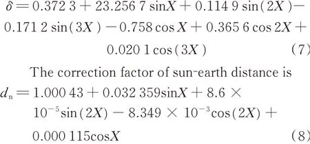
where Pais the atmospheric pressure,θ the angle between the solar ray and the normal to the surface,φ the local latitude,β the tilt angle,γcthe azimuth angle,δ the solar declination angle,ω the solar hour angle,ω=π(τ-12),and τ the solar time. Given the day angle X,the solar declination angle δ and correction factor of sun-earth distance dncan be calculated by

where the 365 days correspond to the interval[0,2π],and D1is the number of days in one year(On 1 January,D1=1;On 31 December,D1=365).

The solar declination angle is
1.2 Calculation model of shadow area between collectors
Fig.1 is a schematic of the shaded model of solar collectors facing the due south direction on the horizontal plane.
As shown in Fig.1,A is the collector width,D the spacing between collectors,L the collector length, Hsthe shadow height,Lsthe shadow length,and Lus=L-Ls.Relative height hsand relative length lsof the shadow of front collector can be expressed as
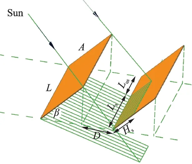
Fig.1 Shaded model of solar collectors
where hsis the relative shadow height,lsthe relative shadow length,d the relative spacing between collectors,γsthe solar azimuth and α the sun altitude.
And
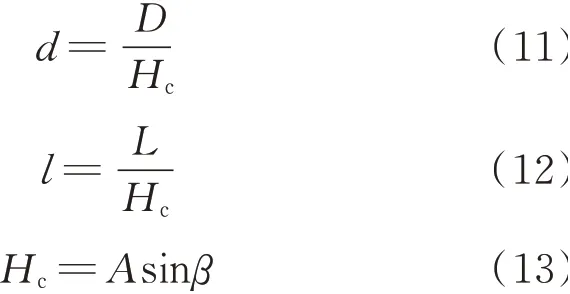
where Hcis the collector height and l the collector relative length.
Fig.2 shows the schematic of solar collector array.
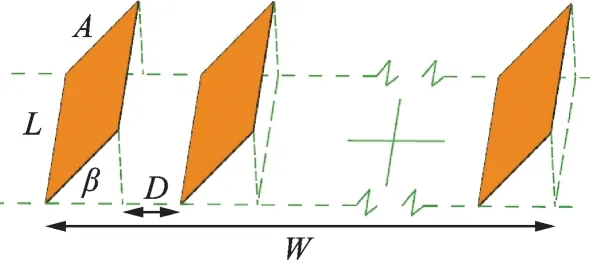
Fig.2 Schematic of solar collector array
As shown in Fig.2,W is the width of the solar collector array. In a limited area if the only one row is installed,the effective collector area is LW/cosβ,the height of the array is Wtanβ,and the array height would be too large. It is unsafe and inconvenient to the later maintenance of the collectors,so the condition of only one row installed is not considered. If the number of the rows is k(k=2,…,km),the spacing between collectors can be calculated by

When the minimum D is taken as Dmin,the corresponding row number is the maximum value km

where Dmin=Hccotαs,and αsis the sun altitude at noon in winter solstice.
If solar collectors are tilted at an azimuth angle of γc,γsin Eqs.(9),(10)would be γ(γ=γs-γc).
The sun altitude angle α and solar azimuth angle γsin the expression above can be expressed as

The shadowing factor s can be given by

Given that the relative shadow height and the relative shadow length are non-negative values,where 0 ≤s ≤1;and assume when s>1,then s=1.
1.3 Solar collected energy of collector array
The solar radiation intensity Itof the first row without shadow in the collector array at any time is written as

The solar radiation intensity I′Sof the surface of the collector array with shading condition can be expressed as

Thus,the radiation intensity on the tilt surface of the collector array is known,the collected energy S can be written by

2 Two Kinds of Evaluation Methods for Optimal Arrangement of Collectors
2.1 The optimal method for the optimized objective of maximum benefit
The economic model is based on the technical code for application of solar water heating system of civil building,of which,the residual income of the system is converted to the cost of natural gas energy saved by the collectors. The input cost consists of the initial investment and the maintenance of the system during the tenure of the contract.
The cost calculation model of solar utilization system is

Maximum the residual income model of the system,shown as

where the initial investment of the system is composed of two parts:One is the cost of the collectors CPV,the other is the cost of other auxiliary equipment,which includes the cost of basic equipment such as intake,drainage and heat storage tank;COis the cost of the basic equipment of the system;CMis the cost for maintenance of the system,which is about 1% of the initial investment in the system;i is the discount rate;dsis the attenuation coefficient of annual energy output in solar utilization system;ε is the conversion coefficient of equivalent substitution between solar energy radiant energy and natural gas;R is the price of natural gas in the market. The system life can be 5,10,15 and other years.
2.2 The optimal method for the optimized objective of minimum annual auxiliary heating energy
The solar radiation energy is the main heat source of the solar electric water heating system,and electric energy is the auxiliary heat source to supply heating when it is necessary. In summary,the auxiliary energy for heating can be calculated by

where QWYis the collected energy by collectors for a year,and ηjthe efficiency of solar collectors. According to the measured data of collector product,the empirical value is 45%—50%;ηlis the heat loss of the storage tank and pipeline,and generally takes 15%—30%[13].
The energy of heating water can be calculated by

where n is the number of people who enjoy the service of solar water heating systems,qdthe water quota for bathing,ρwthe density of water,C the specific heat capacity of water,ΔT the temperature difference of the solar heating. In order to simplify the calculation,some assumptions are given as follows.The hot water demand in winter is about 80 d,the spring and autumn season is 150 d,and the summer is 45 d.
The energy for heating water in winter can be calculated by

The energy for heating water in spring & autumn can be calculated by

The energy for heating water in summer can be calculated by

and the energy for heating water in a year can be obtained by

In Eqs.(26)—(28),qd1,qd2,qd3are the water quota for bathing in winter,spring & autumn and summer,respectively,shown as qd1=22.16 L/(people·d),qd2=18.63 L/(people·d),and qd3=16.68 L/(people·d)[12];ΔT1,ΔT2,ΔT3are the temperature difference of the solar heating in winter,spring & autumn and summer,respectively.
In general,the thermal efficiency of the electric heating system is 90%. The calorific value of ordinary life water is 3 559 kJ/(kW·h). The commercial electricity price on the market is 0.61 yuan/(kW·h),the calculation model of the economic cost of the auxiliary heating energy throughout the year is

where Z is the cost of electric energy in the solar electric water heating system(RMB 104yuan).
2.3 Calculation method and flow chart
The flow chart calculated by visual C++ program is shown in Fig.3.
3 Influence factors of the collected energy
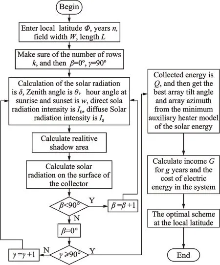
Fig.3 Calculation flow of solar radiation of solar collector array in a year and income of solar power system
The results of this paper take a solar thermal system which is placed on a horizontal plane as an example. The length of the plane is 20 m,and the width is 10 m. The plane is located in Nanjing,Jiangsu Province. The size with 2 m×1 m of collectors is chosen in this research. 0.5 m is selected as the minimum spacing for maintenance.
From the solar radiation model of the solar collectors above,the shadowing of the collectors,the surrounding environment and geographical location of the collectors have a great effect on the solar collected energy. And the mutual shadowing of collector mainly depends on the arrangement of the collectors such as the tilt angle of the collectors,the number of the collector rows,the azimuth of the collectors,etc. This paper focuses on four main factors including the relative shaded area,the collector tilt angle,the row number of collectors and the azimuth angle.
3.1 Relative shaded area of collectors
The front row of the collectors will form a certain area of shadowing on the surface of the backrow collectors because of the angle of solar radiation. The ratio of the shadowing area and the collector area used for absorbing energy is called shadowing factor s. It is also called relative shaded area,and its value is greater than or equal to 0 and less than 1. For the whole year,the mutual shadowing of the solar collectors is the most obvious that the relative shaded area is the maximum in the winter solstice for a year. The variation of the shadowing factor with time in the winter solstice day is plotted,as shown in Fig.4.
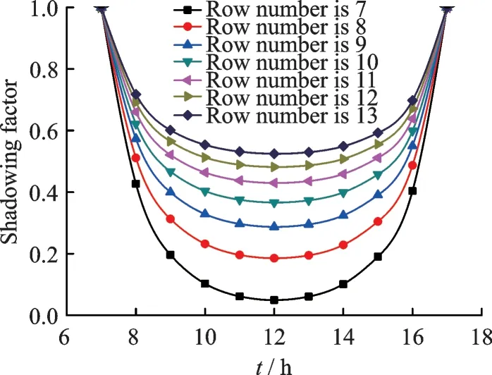
Fig.4 Variation of shadowing factor with time in the winter solstice day
As shown in Fig.4,it would gain the lowest value of the shadowing factor at noon because of the sun altitude angle is the largest at this time and the value of the shadowing factor at noon increases with the row number. On the contrary,in the morning and evening,the lower sun altitude angle makes the shadow larger,the value of the relative shadow area will be larger or close to 1 and the rear row collectors are all covered by shadowing. This performance does not change with row numbers.
3.2 Collector tilt angle
The solar radiation reaching the collectors not only depends on solar radiation intensity,but also on the arrangement of the collectors. The pretreatment azimuth angle is 0°,and the relationship between the solar radiation energy of the collectors and the collector tilt angle with different row numbers of collectors is plotted in Fig.5.
As shown in Fig.5,the annual collected energy increases firstly and then decreases with the increase of the collector tilt angle when the array row numbers are 6 and 7. Significantly,the curves with the row numbers of 8,9,10 show the incomplete shapes. That is because when the collector tilt angle is less than the minimum inclination angles the spacing between the collectors does not meet the minimum spacing of 0.5 m for maintenance.
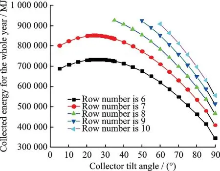
Fig.5 Variation of collected energy for whole year with tilt angle of solar collector array
3.3 Row number of collectors
The row number of collectors which is an important factor affecting the collected energy is the key problem for arranging the collectors in a given field. According to the analysis of Fig.4,the spacing between collectors would change with the row number,which affects the shadowing of the collectors and then leads to an effect on the collected energy. In order to clarify the relationship between the row number and the collected energy,Fig.6 is plotted.
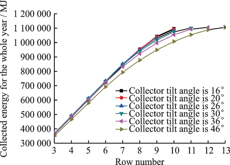
Fig.6 Variation of collected energy for whole year with row number of collector array
Fig.6 shows the relationship between the annual collected energy and the row number of collectors according to different inclination angles. Obviously,the collected energy in different tilt angles increases with the row number and becomes stable at last.For a fixed tilt angle,when the row number is increasing,the total collector surface area increases,and then the shadow area will increase with the decrease of the spacing between the collectors. However,the relative shadowing area always decreases with the increase of row number. Hence,the collected energy increases with row number. It is important to note that the maximum value of the collected energy at different tilt angles is not obvious,because the design requirements have limited the spacing between the collectors. For example,when the array row number is 10 with the tilt angle of 16° ,the maximum collected energy can be obtained. However,according to Fig.6,the optimal layout of the year should be that:the tilt angle is 46°,the row number of collectors is 13. So,the minimum tilt angle does not always obtain the maximum collected energy. Meanwhile,the method of increasing the row number also results in high cost of the solar system,and ultimately affects the total benefit of the system.
3.4 Azimuth angle of collectors
As same as the influential factors of the tilt angles and row numbers of the collectors,the azimuth angle of collectors is also an important factor in the arrangement for the collectors. When the row number is 7,variation of the collected energy for the whole year with the solar collector azimuth is shown in Fig.7.
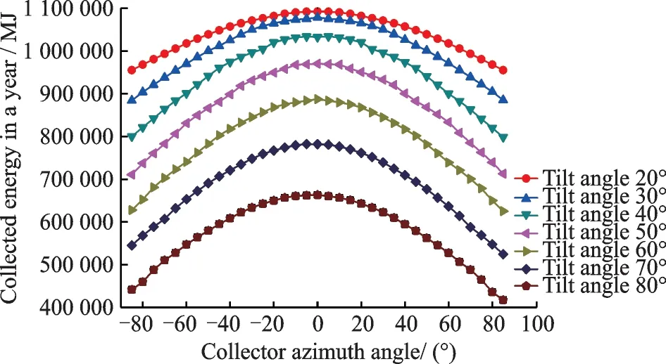
Fig.7 Variation of collected energy for whole year with solar collector azimuth (Row number is 7)
As shown in Fig.7,the collected energy increases firstly and then decreases with the continuous increase of the azimuth angles. Obviously,the maximum valve appears with the azimuth angle of 0° at different tilt angles and this maximum value increases with the increase of the tilt angle.
4 Optimal Arrangement
In the actual process,the collectors are arranged in the limited area. In this paper,the geographical location of the array is 32.2°(N),the area of the array is 200 m2. The collected energy by the system is not sufficient to establish the optimal design of array. Therefore,in this paper two optimized objectives are chosen to obtain the optimal arrangement.
4.1 The optimal methods based on the maximum benefit
The input cost of the system will increase with the increase of the collected energy in a sense.Therefore,the income of the system is the reasonable way to establish the optimal design. The variation of the income of the solar power system in fifteen years with the tilted angle and the solar collector azimuth in different row numbers is shown in Fig.8.
It is worth noting that some points in Figs.8(a)—(c)are not shown because the spacing between collectors is less than 0.5 m. As shown in Fig. 9,the optimal layout of the collectors is that:the number of collector rows is 8,the tilt angle is 40° ,the azimuth angle is 0°. In this way,the total profit of solar utilization system operates for 15 a can be RMB 823.5×10³yuan.
4.2 The optimal methods based on the minimum annual auxiliary heating energy
In the solar electric water heating system,the solar radiation energy should be the main heating source for the operation of the system,but the electrical energy is added for meeting the needs of human life. Both of them are considered in the optimal model. Fig.9 establishes the variation of the annual auxiliary heating and corresponding power consumption cost with the tilted angle and the solar collector azimuth.
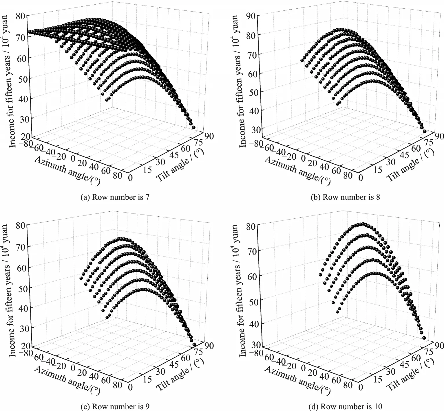
Fig.8 Variation of income of solar power system in fifteen years with tilted angle and solar collector azimuth
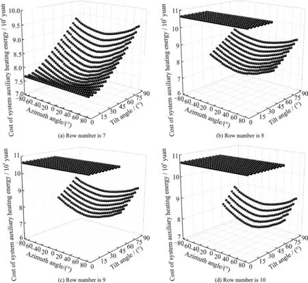
Fig.9 Variation of annual auxiliary heating and corresponding power consumption cost with tilted angle and solar collector azimuth
As shown in Fig.9,based on the optimized objective of minimum annual auxiliary heating energy,the optimal layout of the collectors is that:the number of collector rows is 9,the tilt angles is 50°,the azimuth angles is 0°,and the annual auxiliary heating energy can be 383 310 MJ that cost RMB 7.29×10⁴yuan.
It is needed to explained that there are some points described the same cost of system auxiliary heating energy in Figs.9(b)—(d).These points mean that the arrangement of the collectors does not meet the requirements of the minimum spacing for maintenance,so the heating source of the solar electric water heating system is only provided by electrical energy.
5 Conclusions
Based on the influencing factors of the shadowing of the collectors,the surrounding environment and arrangement of the collectors,the mathematical model of the collected energy by the solar collectors on the horizontal plane in a given field has been established.
The results show that,the collected energy in a year could increase with the increase of the number of collector rows. And the collected solar radiation in a year increases firstly and then decreases with the increase of the collector tilt angles. Furthermore,the collected solar radiation in a year increases firstly and then decreases with the continuous increase of the azimuth angles from -90° to 90°.
And two kinds of evaluation methods are proposed to obtain the optimal arrangement of the collectors in this paper. Based on the optimized objective of maximum benefit,the optimal layout of the solar collector array in the area of 200 m2in Nanjing should include:the number of collector rows is 8,the tilt angle is 40°,and the azimuth angle is 0°.
Meanwhile,the optimal methods for the optimized objective of minimum annual auxiliary heating energy should include:the number of collector rows is 9,the tilt angle is 50°,and the azimuth angle is 0°.
Therefore,the different economic models present the different arrangements of the solar collectors. Nevertheless,economic models should be taken account in the arrangement of the solar collectors particularly in large-scale solar projects. The above research results are not limited to the geographical location of Nanjing.
杂志排行
Transactions of Nanjing University of Aeronautics and Astronautics的其它文章
- Recent Advances in Hole Making of FRP/Metal Stacks:A Review
- Parameter Optimization for Improvement in Biomachining Performance
- Effect of Friction on Dynamic Response of A Power Split Transmission System
- Mathematical Model and Machining Method for Spiral Flute Rake Faces of Hourglass Worm Gear Hob
- Active Design Method of Tooth Profiles for Cycloid Drive Based on Meshing Efficiency
- Design and Study of Virtual Interventional Surgical System with Force Feedback
