Thermodynamic Modeling and Simulation of Air System Control Device
2019-08-01FUJiangfengLIHuacongLIUXianweiHONGLinxiong
FU Jiangfeng,LI Huacong,LIU Xianwei,HONG Linxiong
College of Power and Energy,Northwestern Polytechnical University,Xi’an 710072,P.R.China
Abstract: This paper aims to obtain the thermodynamic characteristics of the air system control device sealing part in different compressor bleed air and ambient temperature. On the basis of considering the main factors affecting the heat exchange process and simplifying the physical model of the air system control device,the thermodynamic model of air system control device is established based on the basic theory of laminar flow heat transfer and heat conduction theory.Then the piston motion characteristics and the thermodynamic characteristics of the air system control device seal are simulated. The simulation results show that the valve actuation dynamic time of piston is about 0.13 s in the actual working conditions,and the temperature effect on the dynamic response of the piston rod is only 5 ms when the inlet air temperature at 300 ℃and 370 ℃. The maximum temperature of the air system control device sealing part is not more than 290 ℃under long time working condition of compressor air entraining. The highest temperature of the sealing part can reach up to 340 ℃when the air flow temperature reaches the limit temperature of 370 ℃,and the longest duration working temperature limit is not more than 14 s. Therefore,the selection of control device sealing material should consider the work characteristic of instantaneous temperature limit.
Key words: aeroengine;air system;air bleed control device;thermodynamic analysis
0 Introduction
Aero-engine air system is one of the important systems of aero-engine. The air system control device realizes the function of cooling and sealing of high temperature components of engine,as well as the functions of axial load control,active clearance control and anti-icing of engine by adjusting external duct flow and compressor bleed air. Its performance is an important factor affecting the safety and reliability of aeroengine[1].
In the last years,a considerable amount of theoretical and experimental work has been carried out on the influence law of air system on engine performance[2-6]. Refs.[7-8]carried out the two-phase flow and heat transfer simulation in complex rotating shaft cavity of air system and lubrication system.Ref.[9]investigated the simple theoretical models,CFD and experiments of the flow and heat transfer characteristics that occur inside the internal coolingair systems of gas turbine engines.Ref.[10].presented one-dimensional steady-state flow network method for prediction and application of pressure,temperature and flow along the engine air cooling system.Ref.[11]presented a modular modeling method for air system with fast transient and establishment of more complex air system network in studying the complex dynamic characteristics and mechanism of aero-engine air system. Ref.[12]presented the modification of the design method of air system and applied this method into the turbine disk design.Ref.[13]investigated the component method to solve the secondary air system and carried out calculations for both steady and transient state problems by using the component method and network method toward series and parallel networks. Ref.[14]presented the design technologies of secondary air system according to functions and design characteristics of the the secondary air system and analyzed the flow characteristic and the fluid temperature using CFD software. By analyzing the above research,it can be found that researchers mainly focus on the mechanism of the compressors flow field and its performance.However,the relevant research on air system control device is seldom published by researchers at home and abroad.It is necessary to carry out indepth study on the air system control devices.
Air system control device’s working condition involved complex heat transfer and thermodynamic processes in practice,temperature and pressure of sealing parts in air system control device are in a transient state at any time,so its sealing performance directly affects the reliability of the air system control device. Therefore,it is necessary to investigate the thermodynamic characteristics change rules of the sealing parts of ais system control device,which caused by the bleed air temperature and the ambient temperature of the air system control device. This paper aims to obtain the thermodynamic characteristics of the air system control device sealing part in different compressor bleed air and ambient temperature. By considering the main factors that affect the heat exchange process and simplifying the actual physical model under the basic assumption of neglecting the secondary factors, the paper established the thermodynamic model of air system control device based on the basic theory of laminar flow heat transfer and heat conduction theory. Finally,the simulation of the thermodynamic characteristics was simulated and analyzed on sealing parts of the air system control device.
1 Air System Control Unit Model
The air system control device is composed of the high-pressure compressor air bleed chamber,compressor bleed air component,electromagnetic valve,piston cavity,external bleed air bleed component and compressor bleed air bleed component.Due to the fact that the actual geometrical model contains many parts and the structure of the shell is complex,the physical model needs to be simplified in calculating its thermodynamic properties. The original physical model is simplified to form a simplified structure of the air system control device,as shown in Fig.1.
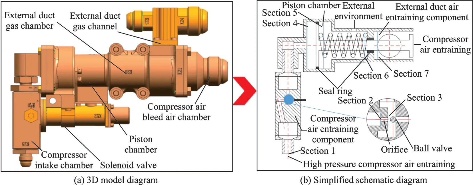
Fig.1 Simplified diagram of air system control device structure
Wherein,the compressor inlet is defined as Section 1,the left side of the orifice component is Section 2,the right outlet of the orifice component is Section 3,the outlet of the compressor air outlet pipe is Section 4,the right side of the piston chamber is Section 5,the left side of the outer air bleed air compartment is Section 6,and the right side of the section of the outer air bleed component is Section 7. Simplify the convex and concave part of the complex shell,ignoring the specific shape of the air filter instead of the cylindrical cavity tube. In the simplification of the piston chamber components,the piston head is considered as a cylinder,the piston rod is an equal-diameter cylinder,ignoring the valve geometry at the right end of the piston rod and is equivalent to a certain mass load. In the simplification of external air induction components,it is considered that the external gas is filled in the cavity,the flow velocity is uniform,and the shape of the specific flow pipe in the external bypass pipe is ignored. In the analysis of high-temperature gas compressor heat transfer through the cone valve calories,the irregular shape of the cone valve heat transfer is ignored,and the piston rod cross-sectional area is considered as the heating area.
2 Thermodynamic Model of Air System Control Device
2.1 The basic assumptions of model
Thermodynamic modeling and simulation need to focus on the factors which mainly affect the heat exchange process,ignoring the secondary factors of heat conduction. The modeling made the following assumptions and simplifications:
(1)Regardless of the transient physical process when the solenoid valve is switched on or off,only steady-state heat exchange process is analyzed.
(2)The air flow in the pipeline belongs to the laminar flow state.
(3)Simplify the gas passage pipelines and consider that the flow of each component belongs to onedimensional steady flow.
(4)Ignoring the thermal resistance of the heat exchange between the surface of the shell and the environment,the shell surface temperature is equal to the ambient temperature.
(5)The gas inside the piston cavity is uniform.
2.2 The flow characteristics air system control orifice
The airflow of the air system control unit is vented at a speed of sound or close to the speed of sound so that the density of the gas can no longer be regarded as a constant,and it can be considered as adiabatic flow due to the extremely fast exhaust flow rate.
When the critical pressure ratio is p2/p1>0.528,the flow rate Qmis obtained as

When the critical pressure ratio is p2/p1=0.528,the flow rate Qmis obtained as

where p1,ρ1,T1are the pressure,density and temperature of the gas in the gas chamber;p2,ρ2are the gas pressure and density of the exhaust port of the nozzle;a1is the sound speed;k is the adiabatic index;and R is the gas constant.
2.3 The kinematics model of single acting cylinder
Air system control device is used in a typical single-acting cylinder. Fig.2 shows the typical structure of a single-acting cylinder,in which qvrepresents the inflow flow,A the piston area,v the piston speed,mΣthe piston equivalent weight,and B the cylinder equivalent damping.
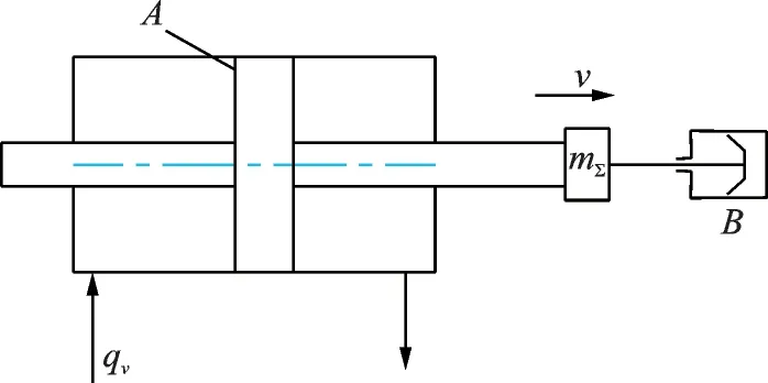
Fig.2 Schematic diagram of single acting cylinder structure
Considering the gas compressibility,load quality,damping and other factors,the piston cylinder kinematics model is shown as

where Vtis the total volume of the hydraulic cylinder;and βethe gas elastic modulus. The change of speed can be obtained by solving the differential Eq.(3)and the displacement of the piston rod is the integral of the speed.
2.4 Heat transfer calculation model of imported air flow
Due to the air system control device gas movement speed is small,consider the flow process as the laminar flow state. In order to describe the heat exchange process in the pipeline better,we need to define the mixing average temperature as

where u represents speed at x axis label,when there is convection heat transfer between the fluid and the inner wall of the pipe. The temperature of the fluid changes continuously with the length of the pipe x.But the dimensionless excess temperature does not change with x.

where twrepresents the wall temperature,tbthe mixing temperature,and t the temperature at a certain point on the cross-section. Although the excess temperature remains constant,the mixing temperature is a single-valued function of the pipe length x.When Prandtl number Pr=1,the thermal boundary layer and the velocity boundary layer developed at the same order of magnitude,assuming an equal thickness and taking into account that the radial velocity of a well - developed zone is zero. Then Eq.(6)is obtained as

Ignoring the thermal resistance between the shell and the environment,the shell surface temperature and ambient temperature are equal,and twis considered as a constant,then Eq.(7)is obtained as


where tbis the mixing average temperature of the fluid at the inlet of the pipeline,tbithe temperature of the incoming stream when the fluid enters the tube at a uniform temperature,and h the pipeline heat transfer coefficient.
The heat transfer coefficient h is determined by experimental correlation. Under constant wall temperature conditions,the effects of pipe bending and turbulence are not considered. The Nusselt number of the normal wall temperature tube obtained by numerical solution of the above equation is

According to the definition of Nusselt number,the convection heat transfer coefficient under different pipeline and flow conditions can be obtained as

2.5 Pipe equivalent thickness and thermal resistance calculation
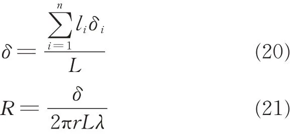
Based on the basic theory of infinite plate heat conduction,the thermal resistance of the shell of the air system control unit is estimated by using the equivalent thickness. Assuming the total length of the pipeline L can be divided into sections,the thickness of the shell is δ1corresponding to the segment l1,the shell corresponding to the thickness δ2of the segment l2,and the corresponding shell thickness δnof the segment ln. The equivalent shell thickness is shown as

The corresponding thermal resistance is

where λ is the thermal conductivity of the shell material,and r the pipe radius.
2.6 Calculation model of piston tail cavity temperature
The solenoid valve closes when the piston completes its actuation. At this point,the high temperature gas in the tail cavity will dissipate the heat to the outside environment. Ignoring the thermal resistance among the cavity air,the external environment and the shell,the heat flux can be expressed as

where R represents the thermal resistance of the cylinder,and tinthe temperature of the inner wall surface as a singular value function of time s.
The loss of gas heat in the tail chamber will result in a decrease of the temperature of the inner wall surface

where t represents the temperature,s the time,and the inner wall temperature changes with time as

where a=-ρgVcp.Eq.(15)should meet the conditions when s=0,tin=t(0).t(0) should be determined by the temperature of the inlet pipe.
2.7 The calculation model of piston rod heat conduction
According to the principle of the air system control device,the temperature on the left side of the piston rod t0is the same as the temperature of the tail gas,and the temperature of the gas in the head chamber is t∞. There is heat exchange between the piston rod and the gas in the head cavity,and the heat transfer coefficient can be obtained through the theory of natural convection heat transfer. The length of the piston rod is L,and the radius is r. At the cross section of length x,the amount of heat that flows in the x direction is Φx,the amount of heat flowing out of the piston rod is Φx+dx,and the amount of heat dissipated by the piston rod to the environment is Φs. It is considered that the thermal conductivity of the material is λ,the surface heat transfer coefficient is h and the cross-sectional areas Acalong the length direction are constants. Piston rod in the radial direction does not change,so it can take a cross-section to analyze. The surface heat transfer resistance 1/h is much greater than the thermal resistance in the piston rod so that the temperature of the piston rod can be considered uniform in either section. After the above simplification,the research problem is transformed into 1D steady-state heat transfer problem.
The basic relationship is shown as

The two boundary conditions are shown as

For the heat transfer coefficient h,we need to calculate the Grash of number based on the relevant parameters[15].
2.8 Sealing part of the thermodynamic characteristics of the calculation process
Based on the independent thermodynamic calculation models of the above components, the change of the temperature of the bleed air in the highpressure compressor is calculated firstly. Secondly,consider the cooling effect of the gas in the tail cavity,and finally calculate the temperature variation in the tail cavity with time. Specific air system control device tail cavity sealing part of the thermodynamic characteristics of the calculation steps are as follows:
Step 1 Calculate the pipe flow from the gas flow parameters and orifice size by Eq.(18)

Step 2 The relationship between velocity,displacement and time can be obtained by solving the piston dynamic characteristic(Eq.(19))

Step 3 Calculate the pipe equivalent thickness and equivalent thermal resistance by Eq.(20)
Step 4 Calculate the outlet flow temperature of the pipeline by Eq.(22)

Step 5 Calculate the thermal resistance of the piston chamber by Eq.(23)

Step 6 Solve the temperature variation of tail cavity by Eq.(24)

3 Simulation of Thermodynamic Characteristics of Sealing Area
According to the working conditions and working characteristics of the air system control device,the inlet pressure of the high-pressure compressor is not more than 2.7 MPa(absolute pressure),the working range of the long-term air blowing temperature is less than 300 ℃and the instantaneous maximum temperature is 370 ℃. Gas inlet pressure is not greater than 1 MPa(absolute pressure),the temperature changes in the range of-55 ℃—300 ℃,the long-term working medium temperature is 220 ℃,air system control device for a long time temperature range of+120 ℃— +176 ℃;the shortterm operating temperature is at the range of+176 ℃— +215 ℃,each flight lasts no more than 3 min,215 ℃ continuous working time not less than 15 min; ambient pressure ranges from 0.003 4 MPa to 0.244 8 MPa(absolute pressure).Air system control device in the long-term working conditions piston seal temperature should be below 300 ℃.
The operating parameters and geometric dimensions of the air system control unit are given in Tables 1—3.
According to the above structural parameters and compressor gas flow parameters simulation,air system control device movement and thermodynam-ic characteristics of the change can be analyzed.
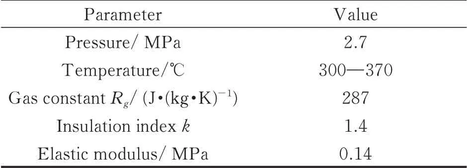
Table 1 Compressor gas flow parameters
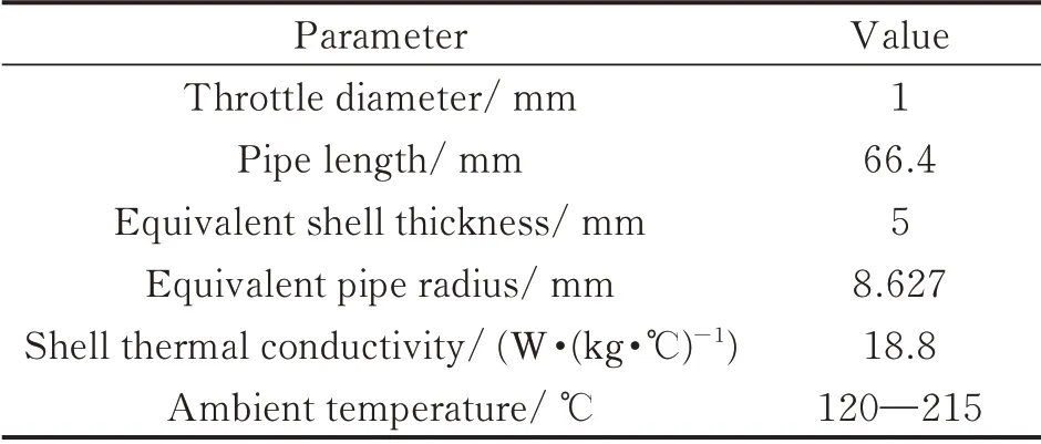
Table 2 Related parameters of compressor bleed air pipeline
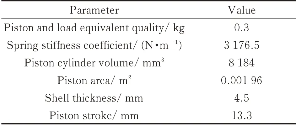
Table 3 Piston cylinder structure parameters
3.1 The change law of air system control device pipeline flow
Fig.3 shows the relationship between air density and temperature.
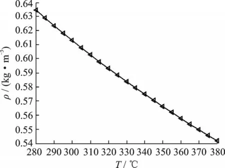
Fig.3 Airflow density changes with temperature
According to the calculation formula of the orifice flow rate characteristic,the gas density,specific heat,viscosity and specific heat capacity change as the temperature of the incoming gas changes. As the temperature increases(Fig.4),the air density shows a downward trend considering the change of incoming gas density,and the change of flow rate of the incoming flow of the compressor in the operating temperature range is shown in Fig.4.
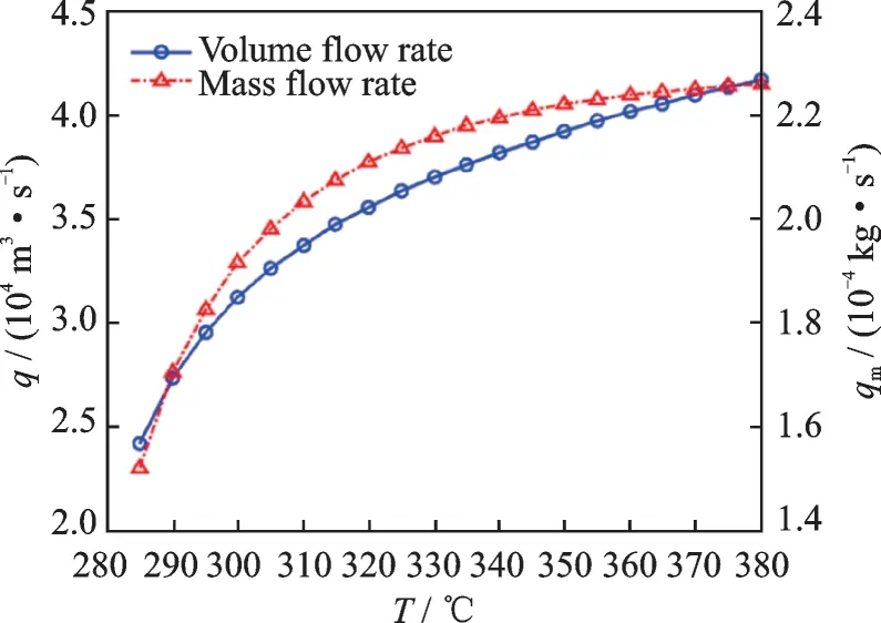
Fig.4 Change law of pipe flow
In Fig.4,when the incoming gas pressure is constant,the volume flow rate and mass flow rate in the pipeline increase as the temperature increases,although the density of the gas flow is decreasing. This is because Q ∝and ρ do not decrease significantly,although the density decreasing with the increasing temperature. However,the temperature increase is very large,so the flow shows a rising trend.
3.2 Simulation of piston rod motion of air system control device
As the flow rate increases with the increasing temperature,the piston rod displacement and velocity characteristics at 300,335 and 370 ℃are analyzed. Fig.5 shows the displacement characteristics of the piston rod under different conditions.
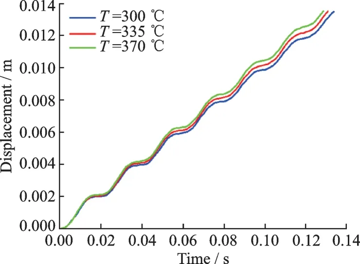
Fig.5 Displacement of piston rod at different flow temperatures
As can be seen from Fig.5,the displacement response of the piston rod is very fast,and the operation is completed after about 0.13 s. In addition,the temperature change in the incoming flow has little effect on the response time of the piston rod,and the response time differs only by 5 ms at 300 ℃and 370 ℃. With the increase of the temperature,the response time of the piston is faster due to the increase of the flow rate.
Fig.6 shows the relationship between the piston rod speed and time under three temperature conditions. It can be seen from Fig.6 that the moving speed of the piston increases firstly and then decreases,and then increases and finally decreases. Due to the damping effect,the amplitude of the increase of the speed decreases in each cycle. However,because the piston belongs to a single-acting cylinder,the damping of the whole moving part is very small,so the piston crawls during the operation. When the temperature increases,the piston rod speed amplitude increases. This is because the flow rate increases to increase the power on the piston,thus shortening the activation time.
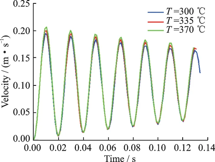
Fig.6 Piston rod response speed and time
3.3 Simulation and analysis of the temperature change of the trailing chamber
Under the conditions of the compressor inlet flow temperature of 370 ℃,and ambient temperatures of 120,176 and 215 ℃,the average temperature of the pipeline is simulated with the change of the pipeline length. Simulation results are shown in Fig.7.
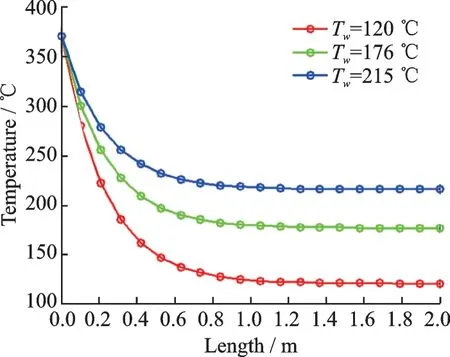
Fig.7 Relationship between outlet and length of the
As can be seen from Fig.7,as the length of the pipe increases,the outlet temperature is declining.The initial declining speed is fast,and as the length increases,the gradient of decline is more slowly.This is because the temperature of the fluid in the pipeline is reduced which caused the drop of the heat flux through the pipeline. In addition,the ambient temperature has a very significant effect on the temperature drop inside the pipe. As the ambient temperature increases,the gradient of temperature drop in the pipeline gradually slows down. This is mainly because the temperature difference is the driving factor of heat conduction. When the ambient temperature rises,the heat loss decreases as the temperature difference decreases.
Fig.8 shows changeable relationship of the different compressor flow temperature and tail sealing temperature.In Fig.8,as the temperature of the compressor increases,the temperature of the air entering the tail chamber rises. Different ambient temperatures have a very significant effect on the temperature of the sealing area inside the tail cavity. When the ambient temperature is low,the airflow dissipates more heat through the tubing and therefore enters the cavity at a lower temperature. With the increase of the ambient temperature,the heat loss of the air flow through the pipeline becomes smaller,and the temperature of the sealed part in the tail cavity also increases. When the compressor air temperature reaches the limit temperature of 370 ℃,the maximum temperature at the sealing part can reach 340 ℃. However,the maximum temperature at the sealing part is not more than 290 ℃when the compressor inlet temperature is 300 ℃for a long time,and it is in a stable working range.
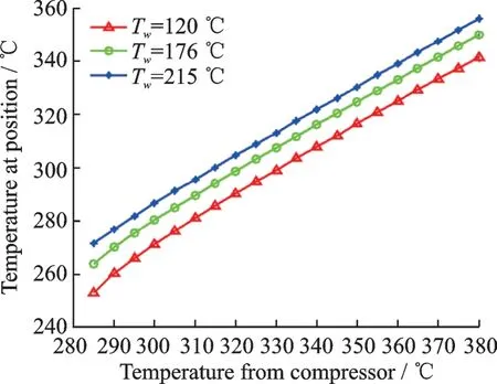
Fig.8 Temperature change law of sealing parts
3.4 Thermodynamic analysis on the sealing area of tail cavity
After the piston completes its operation,the air flow entering the tail chamber will dissipate its own heat to the environment through heat conduction,resulting in a decrease of the internal temperature of the piston. As time goes by,the temperature of the gas inside the tail chamber will eventually agree with the ambient temperature. Table 4 shows the basic parameters of the air system control piston chamber.

Table 4 Piston tail cavity parameters
The above parameters are brought into the method described above,assuming that the initial tail gas chamber temperature is 350 ℃,the ambient temperatures are 120,175 and 215 ℃. The changes of the temperature inside the tail cavity with time are shown in Fig.9.
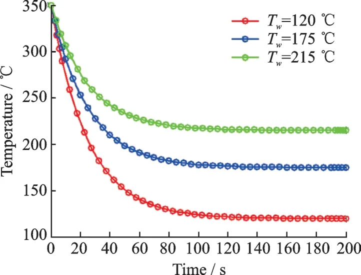
Fig.9 Tail cavity temperature changes over time
In Fig.9,the temperature in the tail cavity stabilizes within 125° to 240°,depending on the external environment. Over time,the temperature of the gas in the tail cavity gradually decreases until it reaches the same temperature as the outside world.Different stages of the temperature decline is not at the same speed. With the tail cavity temperature decreases,the temperature changes more and more gently. This is because the shrinking of the temperature makes the tail cavity to reduce the heat flow inside and outside,so the temperature changes tend to be gentle.
This type of air system control device tail sealing section of the selected seal ring,can withstand the ultimate temperature of 300 ℃. According to the variation of the temperature inside the tail cavity with time,the simulation results of the over-temperature inside the tail cavity are shown in Fig.10.
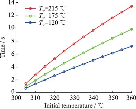
Fig.10 Sealing ring over-temperature time
Fig.10 shows the relationship between the overtemperature of the tail cavity and the initial temperature. It can be seen that the over-temperature time inside the tail cavity is short as the ambient temperature decreases. This is because the decline of the ambient temperature,resulting in an increase of heat flow per unit time,enhances the cooling effect of the gas inside the tail cavity. As the initial temperature increases,over-temperature time will be longer. When the ambient temperature at a maximum temperature of 215 ℃,the initial temperature is 360 ℃,and the sealing ring needs to withstand the ultra-limit temperature of about 14 s. In different ambient temperatures,the over temperature time at the sealing ring is 1—14 s. Therefore,the air system control device should be able to withstand short-term high temperature overrun in selecting sealing ring material to meet the system requirements.
4 Conclusions
The following conclusions can be drawn from the simulation study on the operating performance of the air system control device piston and the thermodynamic characteristics of the seal,under the actual operating conditions of the compressor air bleed temperature of 300 ℃—370 ℃and the ambient temperature of 120 ℃—215 ℃:
(1)Piston actuation time of the air system control device is about 0.13 s,and the flow rate caused by the temperature change of the flow of the air stream has little effect on the response time of the piston rod.The response time difference is only 5 ms when the compressor incoming flow temperature at 300 ℃and 370 ℃.
(2)The temperature of the sealing part of the air system control device can meet the design requirement of less than 300 ℃. When the compressor bleed gas is at an extreme state of 340 ℃or more,the temperature at the seal ring has an over-limit phenomenon,but the temperature over-limit is transient and the longest duration is about 14 s. Therefore,when choosing the material of the sealing ring, the instantaneous temperature limit seal should be considered to work normally.
AcknowledgementsThis work was supported by the National Major Special Projects for Gas Engine and Aero Engine (No. 2017 - V - 0013), the Aviation Funds (No.20150653006), and the Fundamental Research Funds for the Central Universities(No.G2017KY0003).
AuthorsDr.FU Jiangfeng is an associate professor at the School of Power and Energy,Northwest Polytechnic University,China. He received his Ph.D. degree in the aerospace science and technology from Northwest Polytechnic University in 2013. His current research interests include modeling and simulation of aeroengine control system,and design and simulation of aviation fuel pump.
Prof. LI Huacong has been working in the School of Power and Energy,Northwest Polytechnic University,China. He received his Ph.D. degree in the aerospace science and technology from Northwest Polytechnic University in 2008. His research fields are aeroengine control,fuel gear pump design,centrifugal pump design and fuel control system design and simulation.
Mr. LIU Xianwei is a Ph.D. candidate at the School of Power and Energy,Northwest Polytechnic University,China.He obtained his M.S. degree in Northwest Polytechnic University in 2015.At present,his main research field is the simulation and analysis of internal flow field of aviation fuel centrifugal pump.
Mr. HONG Linxiong is a Ph.D. candidate at the School of Power and Energy,Northwest Polytechnic University,China. He obtained his B.S. degree in Northwest Polytechnic University in 2017. At present,his main research field is modeling,simulation and optimization design of aviation fuel control system.
Author contributionsDr. FU Jiangfeng designed the study and contributed to the review of controllability. Prof.LI Huacong contributed to the overall research plan of the study. Mr. LIU Xianwei contributed to the simulation and calculation. Mr. HONG Linxiong contributed to the analysis of simulation data. All authors commented on the manuscript draft and approved the submission.
Competing interestsThe authors declare no competing interests.
杂志排行
Transactions of Nanjing University of Aeronautics and Astronautics的其它文章
- Recent Advances in Hole Making of FRP/Metal Stacks:A Review
- Parameter Optimization for Improvement in Biomachining Performance
- Effect of Friction on Dynamic Response of A Power Split Transmission System
- Mathematical Model and Machining Method for Spiral Flute Rake Faces of Hourglass Worm Gear Hob
- Active Design Method of Tooth Profiles for Cycloid Drive Based on Meshing Efficiency
- Design and Study of Virtual Interventional Surgical System with Force Feedback
