Dynamics Analysis of Carrier-Based Aircraft with Off-Center Catapult Launch
2019-08-01ZHOUJinZHUJianhuiTONGMingbo
ZHOU Jin,ZHU Jianhui,TONG Mingbo*
1.School of Aeronautic Science and Engineering,Beihang University,Beijing 100191,P.R.China;
2.College of Aerospace Engineering,Nanjing University of Aeronautics and Astronautics,Nanjing 210016,P.R.China
Abstract: In order to enhance the safety of the catapult launch of the carrier-based aircraft,the catapult launch multibody dynamic model is established aiming at the problem of off-center catapult launch. The whole catapult process including four stages which are buffering,tensioning,releasing and taxiing is taken into consideration and the body dynamics of the off-center catapult during each stage is analyzed. The catapult launch dynamic differences between the conditions only considering taxiing and that considering four stages are compared,and the effects of the different initial off-center distances considering four stages on the attitude,landing gear load and acceleration of the carrier-based aircraft during catapult launch are discussed. The results show that only considering taxiing may underestimate the dynamics of the carrier-based aircraft substantially. When taking four stages into consideration,the initial off-center distance has small influence on the aircraft dynamic characteristics during buffering and tensioning but has larger influence on that during releasing and taxiing. The increase of the off-center distance will cause the enhancement of the aircraft rolling and yawing,which may lead to the load difference between the left and right landing gears and the increase of the aircraft lateral acceleration. The establishment and simulation of the catapult launch multi-body dynamic model founded on buffering,tensioning,releasing and taxiing provide reference for the carrier-based aircraft design and analysis of the catapult launch dynamics.
Key words: carrier-based aircraft;catapult launch;off-center distance;attitude angle;landing gear
0 Introduction
The carrier-based aircraft is the core equipment of the carrier fleet. The success or failure of its catapult launch will affect the battle effectiveness of the entire carrier fleet directly. For this reason,it is crucially important to study the process of the carrierbased aircraft’s catapult launch.The catapult launch,referring to the ejecting force of the catapult acting on the carrier-based aircraft,can make the aircraft reach the launching speed in a short time so that the aircraft will take off from the deck with limited length.
A number of studies have been carried out on the catapult launch of the carrier-based aircraft by domestic and abroad scholars. The studies mainly focus on the performance and test of the catapult[1-3],dynamics simulation of the catapult process[4-13],the catapult of the carrier-based aircrafts considering complex environmental effects[14-15]and other relating fields. Small[1]obtained the trajectory of the connecting line midpoint of the main landing gear by off-center position ground catapult test of E-2A and XAJ-1. Lucas[2]studied the effects of the performance parameters of five types of carrierbased aircrafts on catapult launch. Ramsey et al.[3]conducted experimental study on the matching suitability between A-6A aircraft and H-8 hydraulic system. Many scholars have analyzed the problems of off-center catapult[4-8]and off-deck sinking[9]by establishing the six DOFs catapult model[10-11]or multibody catapult model[12]and other modeling methods. In Ref.[13],the catapult launch results agree well with the trajectory of F-4. Refs.[14]investigated the catapult launch of the carrier-based aircraft under the condition of deck pitching and analyzed the effects of the longitudinal motion of the deck on the catapult launch performance. It can be found that the above-mentioned studies all simplified the aircraft catapult process. However,these studies only analyzed the catapult force during taxiing and catapulting dynamics while the carrier-based aircraft will experience buffering,tensioning,releasing and taxiing processes before taking off from the deck in practical cases. The three loaded stages before the catapult have significant effects on the initial taxiing condition. To date,there are no thorough researches on the effects of four stages on the catapult launch dynamic characteristics and analysis of off-center catapult.
In this study,attention is focused on the offcenter catapult launch. The work includes two main parts with several sections. In the first part,a multibody catapult launch dynamic model of the carrierbased aircraft is established. Then,the dynamic differences of the carrier-based aircraft between the catapult condition only considering taxiing and that considering four stages are compared. In the second part,the effects of the initial off-center distance on the dynamic characteristics of the carrier-based aircraft during the stages of buffering,tensioning,releasing and taxiing are investigated by the simulating calculation model and the dynamic origins are analyzed.
1 Off-Center Catapult Launch Modeling
1.1 Coordinate system establishment and model assumption
The catapult launch of the carrier-based aircraft contains four stages:buffering,tensioning,releasing and taxiing. During this process,the forces on the aircraft are body loads that include gravity of the aircraft and the engine thrust,aerodynamic forces that include lift force,drag and side force,the force between the tire and deck and ejecting force. According to the force characteristics of the airframe,the ground coordinate system Ogxgygzg,the on -board coordinate system Obxbybzband airflow coordinate system Oaxayazaare established,respectively. The origin of the ground coordinate system is located at the beginning point of the sliding rail of the catapult on the deck and that of the body coordinate system is just the barycenter of the airframe,as shown in Fig.1.The coordinate systems can be transmitted to each other by coordinate transformation matrix.
The model has the following assumptions:
(1)Ignore the movement of aircraft carrier.
(2)The mass ofthe airframe and the wing concentrates on the barycenter of the aircraft.
(3)The airframe,landing gears and catapult are all rigid bodies.
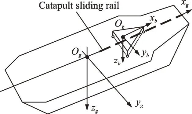
Fig.1 Coordinate system of catapult launch
1.2 Off-center catapult model
According to the connection between carrierbased aircraft and slider,the catapult mode can be divided into nose wheel traction catapult and towing catapult. In this paper,the ejecting force is exerted by nose wheel traction. The catapult launch system shown in Fig.2 can achieve the following functions:
(1)The catapult force is exerted to the airframe by the connections among slider,launch bar and nose landing gear.
(2)The holdback bar connects the nose landing gear and the deck. During the exertion of the catapult preload and catapult force,the aircraft is fixed at the position of pre-catapult launch and will be released by the holdback bar when the contain force reaches the minimum limit value.
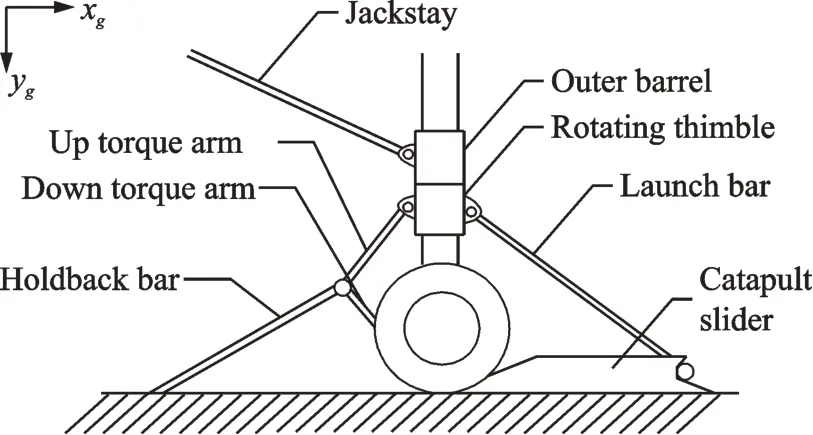
Fig.2 Nose landing gear catapult launch system
(3)The relative rotation between the outer barrel and rotating thimble locate the aircraft at the position with initial off-center distance,as shown in Fig.3.
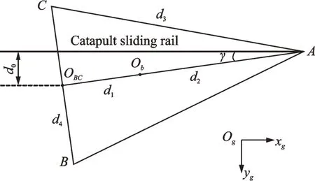
Fig.3 Definition of initial off-center distance
The definition of the off-center distance[16]is the distance from the midpoint of the connection line of the main landing gears’tires to the catapult sliding rail,as shown in Fig.3. Point A is the location of the nose landing gear,while Point B and Point C are where the main landing gears locate. The barycenter of the aircraft is represented by Oband OBCis the midpoint of the main landing gears. The initial off-center distance is represented by d0while the right shift of the aircraft is assumed as positive. The distance from the barycenter of the aircraft to the midpoint of the main landing gears is represented by d1while d2is the distance from the barycenter of the aircraft to the nose landing gear. The distance between the nose landing gear and each main landing gear is represented by d3while d4is the distance between the left main landing gear and the right main landing gear. Symbol γ is the initial yawing angle of the aircraft due to the initial off-center distance while the right shift of the aircraft is assumed as positive. The relation between the initial off-center distance and the initial yawing angle is

1.3 Dynamic modeling of multi rigid body
The analysis of forces acting on aircraft during catapult launch is shown in Fig.4.
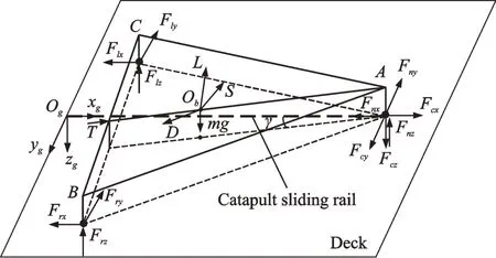
Fig.4 Analysis of forces acting on aircraft during off-center catapult launch
In Fig.4,Fcx,Fcyand Fczare x,y and z components of the catapult force in the ground coordinate system,respectively. Fnx,Fnyand Fnzare course friction,side friction and bearing reaction between the tires of the nose landing gear and the deck,respectively. Flx,Flyand Flzare the course friction,side friction and bearing reaction between the tires of the left main landing gear and the deck,respectively.Frx,Fryand Frzare the course friction,side friction and bearing reaction between the tires of the right main landing gear and the deck,respectively. Symbol g defines the gravity acceleration,m the mass of the carrier-based aircraft,T the engine thrust,L the aerodynamic lift,D the aerodynamic drag,S the aerodynamic side force and h is the distance from the aircraft barycenter to the horizontal plane of the ground coordinate system.
Take the airframe,landing gears and tires as a whole system and establish the dynamic equations of six DOFs during the catapult launch of the carrierbased aircraft in the ground coordinate system Ogxgygzgbased on the Newton’s second law and theorem of moment of momentum.

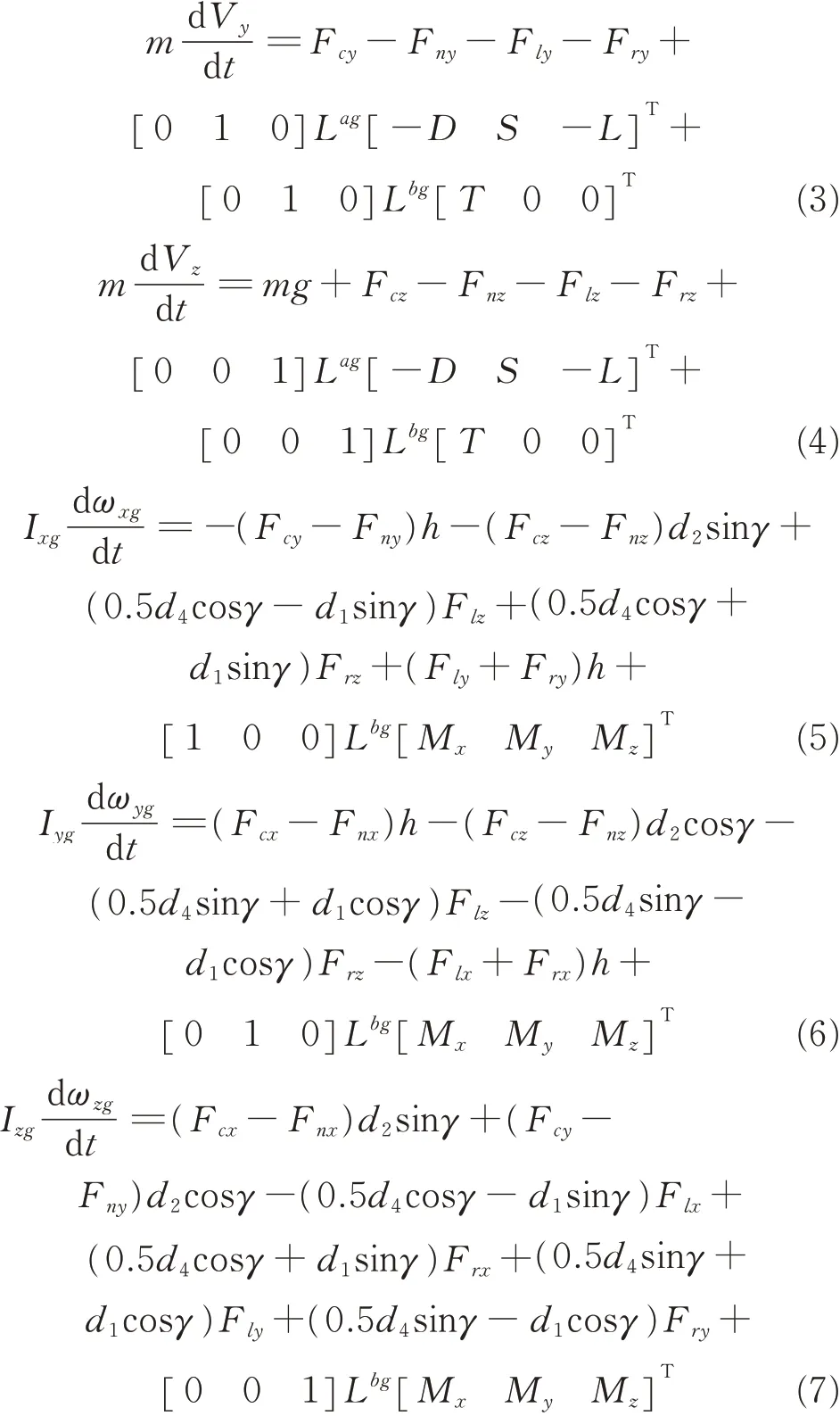
The resultant moment in Eqs.(5)—(7)transformed to the on-board coordinate system is given as

where Vx,Vyand Vzare the aircraft velocities in the ground coordinate system. ωxg,ωygand ωzgare the aircraft’s angular velocities in the ground coordinate system;Ixg,Iygand Izgrepresent the rotational inertia in the ground coordinate system;ωx,ωyand ωzare the aircraft’s angular velocities in the on-board coordinate system;Ix,Iyand Izdenote the rotational inertia in the on-board coordinate system;Mx,Myand Mzare the aircraft’s aerodynamic rolling moment,pitching moment and yawing moment in the onboard coordinate system,respectively. The transposed matrix from airflow coordinate system to ground coordinate system is represented by Lagand Lbgis the transposed matrix from on-board coordinate system to ground coordinate system.
The catapult launch multi rigid body dynamic model is set up in this study,as shown in Fig.5,which conforms to reality better. All the rigid bodies are connected by motion pairs including rotating pair,cylindrical pair and fixed pair. For each body in the multi rigid body model,motion equations in the ground coordinate system are established based on the Newton’s second law and theorem of moment of momentum. The relative motion pairs are used as the constraint condition and all the dynamic equations of the rigid body are combined in the model simultaneously. Then,the relative constraint is transformed into the constraint equation and applied to the system[17-19]. And then these equations are assembled into the Eqs.(2)—(7). Finally,the overall dynamic equation of the multi rigid body model can be achieved.
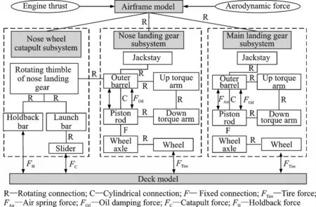
Fig.5 Structure of multi rigid body model during catapult launch
1.4 Force model of the multi rigid body components
In the overall dynamic equation of the multi rigid body model during catapult launch,the number of unknowns is more than that of equations. Therefore,the force equation needs to be established.During catapult launch,the force of aircraft includes the force of the landing gear shock absorber,force between the tires and the deck,catapult preload,and catapult force,limiting force of the holdback bar,engine thrust,aerodynamic force and the gravity of each rigid body component.
1.4.1 Force of the landing gear shock absorber
The single cavity oil-air shock absorber is used in landing gears. Compared with other shock absorbers,this kind of shock absorber is more efficient and has a larger capacity to absorb energy,so it is more suitable for the carrier-based aircrafts. The force of the landing gear shock absorber includes oil damping force,air spring force and structural friction of the shock absorber. The structural friction is so small that it can be ignored compared with the other two forces.
Air spring force is shown as

where V0represents the initial volume of the air chamber;P0is the initial pressure of the air chamber;Aais the cross-sectional area of the air chamber;s is the stroke of the shock absorber and k denotes the gas poly tropic index.
Oil damping force is shown as

where Cdis the oil contraction coefficient;ρoilis the oil density;Ah0is the cross-sectional area of the piston rod;ds/dt is the compression velocity of the shock absorber;Ad0is the cross-sectional area of the oil hole.
1.4.2 Force between the tires and the deck
The force between the tires and the deck includes course rolling friction,side sliding friction and the bearing reaction of the deck.
Course rolling friction is shown as

where μnand μmdenote the friction coefficients of the tires of nose landing gear and main landing gear,respectively.
Side sliding friction(FlyFryFrx)[14]is

where Stis the amount of compression of the tire;D is the diameter of the tire;W is the width of the tire;P is the practical inflated pressure of the tire;PRis the rated inflated pressure of the tire;Ccis the side yawing coefficient of the tire which depends on the tire type;θsis the side yawing angle of the tire.
For the tires of the nose landing gear,it keeps parallel to the catapult sliding rail during catapult launch. The side yawing angle of the tires is so small that the side sliding friction of the tires of the nose landing gear can be ignored.
The bearing reaction of the deck Fz[20]is

where δ is used to define vertical compression amount of the tire.
1.4.3 Gravity and engine thrust
The sum of all the rigid bodies’mass is 25 t.The engine maintains the maximum thrust which is 98 895 N (twin - engine) during the catapult launch.
1.4.4 Limiting force of the holdback bar
The minimum releasing force of the releasing device in Ref.[21]is just the minimum limiting force of the holdback bar in this study,shown as

1.4.5 Catapult force
The catapult force of the slider during the catapult launch contains two parts,which are catapult preload and catapult force. Before releasing,the preload of the launch bar applies the horizontal component force which is 24 500 N of the slider in Ref.[21]. The catapult preload fixes the aircraft on the deck by the launch bar and holdback bar. Then the catapult force is exerted,the catapult force -stroke curve is obtained by the method in Ref.[21].The C13-1 catapult is applied and its catapult forcestroke curve is given in Fig.6.
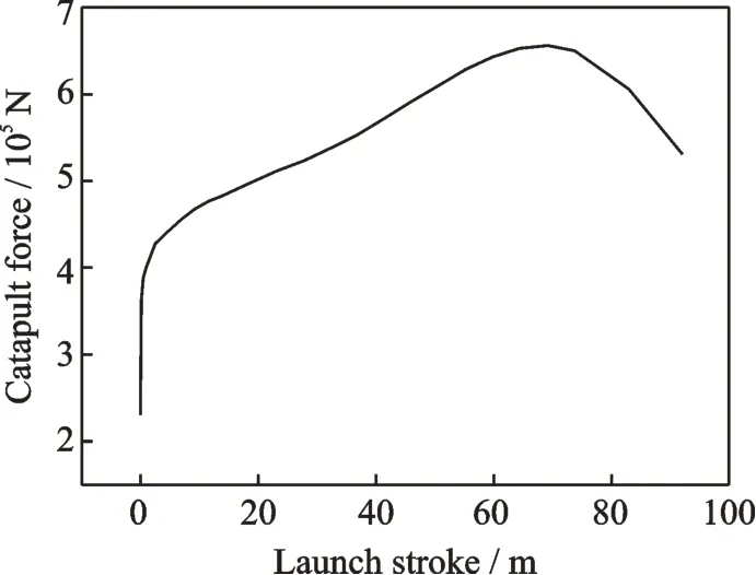
Fig.6 Catapult force-launch stroke curve
2 Analysis of Examples
Ref.[21]has stipulated that the initial off-center distance is no more than 24 inch. Therefore,the initial off-center distance of the examples is±0.609 6 m,±0.30 m and 0 m.
When considering the whole catapult process,the time corresponding to each stage is given in Table 1. By calculation,the time period from 0—39.5 s is the buffering stage and during this stage,the carrier-based aircraft is not affected by the preload,catapult force and engine thrust.When the time is 39.5 s,under the effects of the gravity and landing gear shock absorber,the aircraft engine is shut down,which is the equilibrium state. In this state,the displacement and acceleration of the aircraft in Z direction are nearly zero. After 39.5 s,the engine thrust begins to take effect,the catapult preload which is 24 500 N and lasts for 15.5 s keeps the aircraft ready to take off. After 55 s,the catapult force calculated above is exerted. At the moment of 59.503 s,the force of the holdback bar reaches the minimum limiting force and the bar releases the aircraft. Then,the aircraft is catapulted off and begins to slide on the deck. At the moment of 62.995 s,the slider releases the aircraft. Finally,the aircraft takes off from the ship. The time history curve of the catapult slider force is shown in Fig.7.

Table 1 Time of each stage during catapult launch
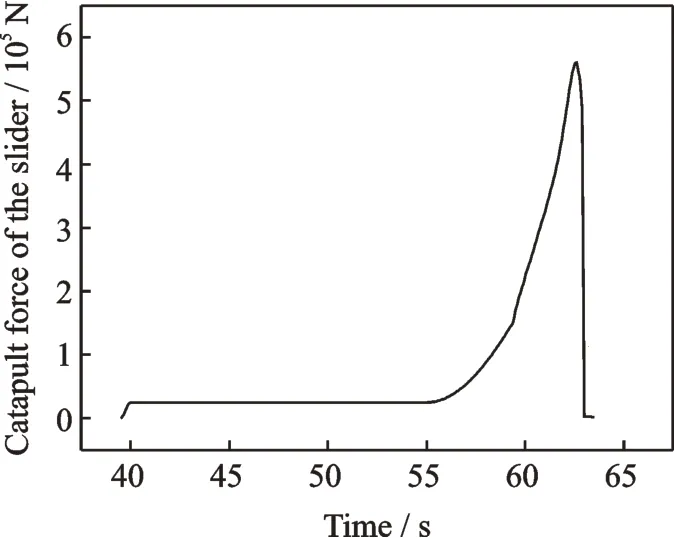
Fig.7 Time history curve of the catapult slider force
The catapult force-launch stroke curve of the sliding block in the catapult launch model which only considers the taxiing stage is illustrated in Fig.6.The time of the acting force is 0—2.935 s. At the moment of 0 s,the carrier-based aircraft is ejected out. At the moment of 2.935 s,the launch bar is separated from the sliding block and the aircraft takes off from the deck.
According to the force equations and data above and the overall dynamic equation of the multi rigid body model,the calculations of the model are made as follows.
2.1 The comparison of catapult dynamic characteristics of aircraft considering four stages and only taxiing
In order to compare the differences in the dynamic characteristics of the aircrafts under the two cases,all the conditions are the same except the applying of the catapult force and the initial off-center distance is 0.Fig.8 shows that when considering taxiing individually,the pitching angle of the aircraft reaches its maximum at the early stage of the taxiing process during catapult launch and the value is 0.436°. With respect to considering the four stages,the maximum and minimum of the aircraft pitching angle occur before and after the releasing stage during catapult launch, and they are 1.169° and-1.09°,respectively.
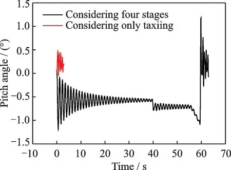
Fig.8 Aircraft pitch angle during catapult launch
It follows from Fig.9 that when only considering taxiing,the Z-direction force of the aircraft nose landing gear reaches its maximum at the early stage of the taxiing process during catapult launch and the value is 144 615.5 N. When considering the four stages,the Z -direction force of the aircraft nose landing gear reaches its maximum at the releasing process during catapult launch and the value is 219 075.14 N.
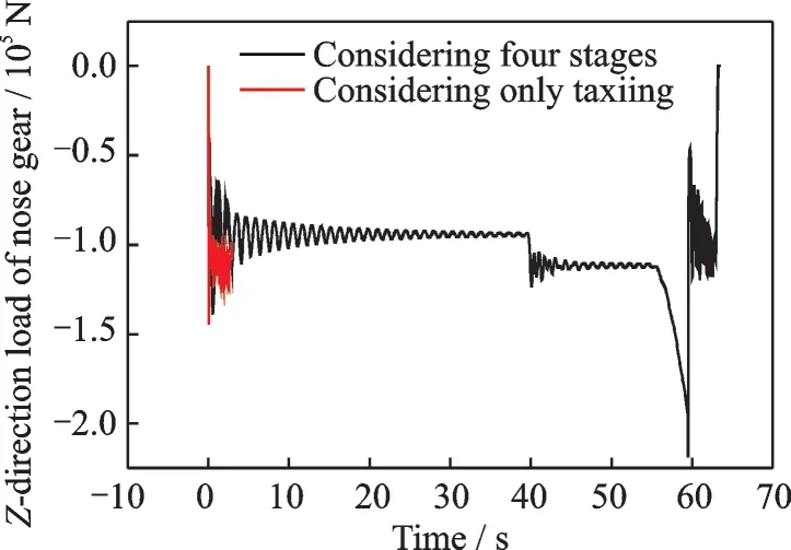
Fig.9 Nose landing gear Z-direction load of aircraft during catapult launch
From Figs.8,9,it can be known that in the analyses for which the taxiing is only considered,the maximum pitching angle and Z-direction load of nose landing gear are much smaller than the aircraft dynamic characteristics considering four stages of the whole catapult process and they only account for 37.3% and 66.0% of the condition considering four stages of the whole catapult process. The difference between the two conditions in dynamic characteristics since during buffering and tensioning stage,under the combined effect of the catapult force and contain load,the nose landing gear buffer is compressed slowly with the increase of the catapult force. At the moment of catapult,the buffer energy reaches its maximum. However,when considering taxiing,there is no similar slow balancing process.At the moment of catapult,the buffer is compressed and then released due to the catapult force. The two conditions have big differences in the dynamic process. When analyzing dynamic characteristics of catapult launch of the carrier-based aircrafts,the calculation results will be severely small if only considering the catapult force during taxiing,and the results do not agree with the real condition of catapult launch. Therefore,the dynamic characteristics of the catapult launch of the carrier-based aircraft with four stages are calculated and analyzed in the following.
2.2 The effect of initial off-center distance on attitude angles of aircraft considering four stages
The initial off-center distance barely affects the pitching angle of the aircraft. As shown in Figs.10—11,it is obvious that the time history curves are almost the same as the initial off-center distance changes. At the moment of the holdback bar releasing the aircraft and the aircraft taking off from the deck,the pitching angle of the carrier-based aircraft has a trend of increasing. During taxiing,the pitching angle has a feature of damped oscillation due to the shock absorber of the landing gear.
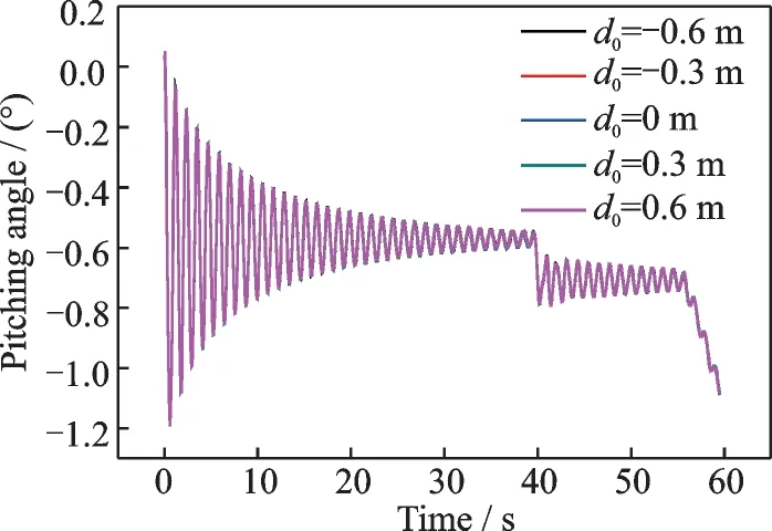
Fig.10 Aircraft pitching angle with different off-center distances during buffering and tensioning
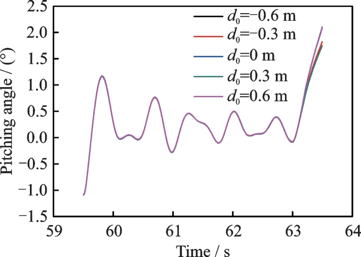
Fig.11 Aircraft pitching angle with different off-center distances during taxiing
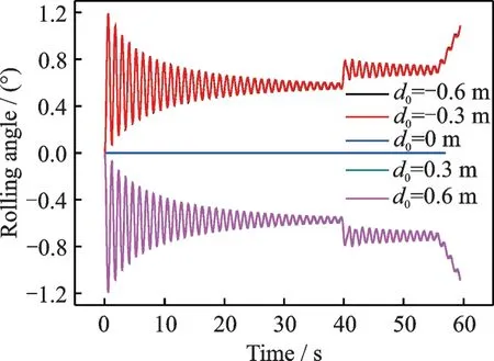
Fig.12 Aircraft rolling angle with different off-center distances during buffering and tensioning
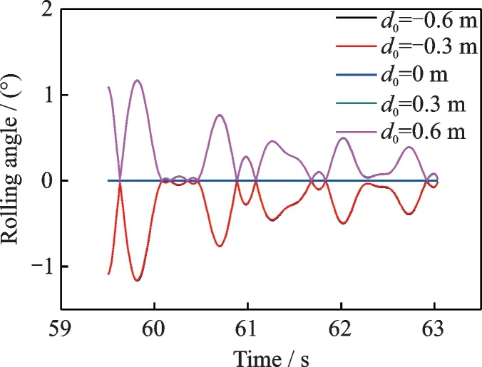
Fig.13 Aircraft rolling angle with different off-center distances during taxiing
The initial off-center distance has a large effect on rolling angle of the aircraft during catapult launch. As shown in Figs.12—13,when the initial off-center distance is zero,the rolling angle of the aircraft is also zero. When the initial off-center distance is more(or less)than zero,which means the aircraft shifts to the right(or left)at the initial moment,the rolling angle of the aircraft is less(or more) than zero during catapult launch,which means the aircraft rolls towards the left(or right).When the signs of the initial off-center distance are the same,the rolling angle curves are nearly the same with the absolute value of the initial off-center distance increasing. During taxiing,the rolling angle has a feature of damped oscillation due to the shock absorber of the landing gear.
The initial off-center distance has a considerable effect on yawing angle of the aircraft. As shown in Figs.14—15,when the initial off-center distance is zero,the yawing angle of the aircraft is also zero.When the initial off-center distance is more(or less)than zero,the yawing angle of the aircraft is more(or less)than zero during catapult launch. Due to the catapult force,the yawing angle has an obvious decline trend. When the signs of the initial off-center distance are the same,the yawing angle becomes bigger as the absolute value of the initial off-center distance increases. The yawing angle curve would not oscillate when 2 s after the holdback bar releases the aircraft,and the yawing angle almost keeps zero till the aircraft takes off from the ship.
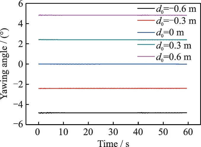
Fig.14 Aircraft yawing angle with different off-center distances during buffering and tensioning
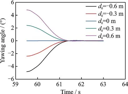
Fig.15 Aircraft yawing angle with different off-center distances during taxiing
2.3 The effect of the initial off-center distance on the force of the landing gear considering four stages
The reference coordinate system of the landing gear force in this study is the ground coordinate system. The calculation results are shown in Figs.16,17.
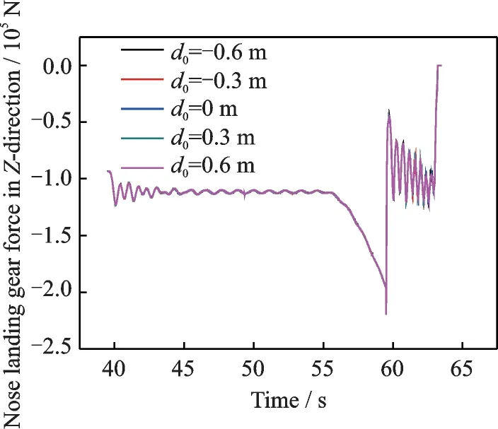
Fig.16 Nose landing gear force in Z-direction with different off-center distances during tensioning and taxiing
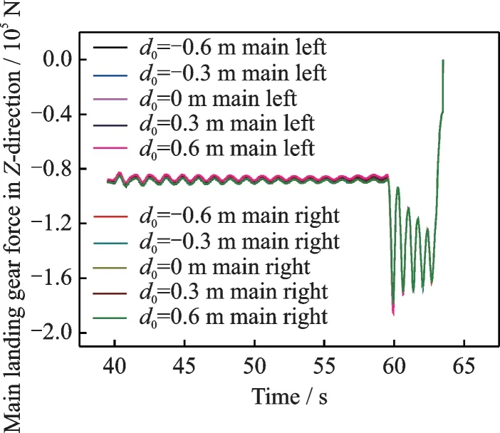
Fig.17 Main landing gear force in Z-direction with different off-center distances during tensioning and taxiing
The initial off-center distance has little effects on the nose landing gear force. As shown in Fig.16,the nose landing gear is connected to the slider on the deck by the launch bar and the nose landing gear keeps parallel to the catapult sliding rail during the catapult launch,the nose landing gear force in Z-direction would not change with of the initial off-center distance. With the exertion of the catapult force,the absolute value of the landing gear force increases and reaches the maximum when the holdback bar releases the aircraft. Then,the landing gear force has a trend of damped oscillation because of the shock absorber and it will reduce to zero after the aircraft takes off.
The initial off-center distance has a certain effect on the main landing gear force. The initial offcenter distance leads to the existence of the rolling angle of the aircraft which may cause the force of the left and right main landing gear differs and their vertical loads are different. As shown in Fig.17,at the initial stage of tensioning and releasing,the most differentia of vertical load between left and right main landing gear are 5.95% when the off-center distance is 0.6 m. With the decrease of the rolling angle of the airframe,the difference of the vertical load of the left and right main landing gear decreases gradually and is approximate to zero.
2.4 The effect of initial off-center distance on aircraft acceleration considering four stages
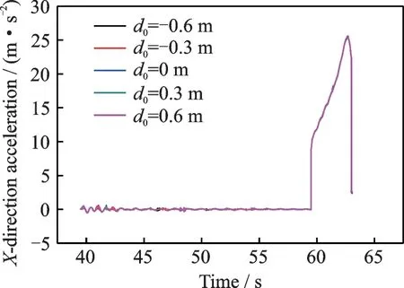
Fig.18 Main landing gear X-direction acceleration with different off - center distances during tensioning and taxiing
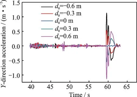
Fig.19 Main landing gear Y-direction acceleration with different off - center distances during tensioning and taxiing
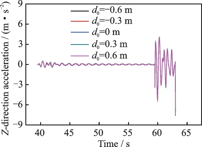
Fig.20 Main landing gear Z-direction acceleration with different off - center distances during tensioning and taxiing
The initial off-center distance has little effects on the aircraft acceleration in X and Z directions while it influences the Y-direction acceleration during taxiing significantly. As shown in Figs.18—20,when the holdback bar releases the aircraft,X-direction acceleration changes with the catapult force.The Y-direction acceleration increases as the initial off-center distance increases. The change of Z-direction acceleration is related to aerodynamic force and shock absorber of the landing gear.
3 Conclusions
The main conclusion of the paper can be summarized as follow:
First,the simulation results of the catapult condition that only considers taxiing differ a lot from the condition that considers the whole process including buffering,tensioning,releasing and taxiing. When only considering taxiing,the pitching angle and the maximum of the nose landing gear load are only 37.3% and 66.0% respectively of those in the condition consider the four stages.
Second,when considering four stages,the yawing angle is influenced by initial off-center distance a lot and it has an approximately linear decreasing trend. The initial off-center distance has a little influence on rolling angle and pitching angle which has a feature of damped oscillation during taxiing.
Third,when considering four stages,the initial off-center distance has negligible effects on nose landing gear load. During the process of tensioning and taxiing,the main landing gear is affected by initial off-center distance greatly. The difference of the two-side main landing gear vertical loads increases with the initial off-center distance.
Fourth,when considering four stages,the Xand Z-direction accelerations of the carrier-based aircraft are slightly influenced by initial off-center distance while the Y - direction acceleration is influenced by initial off-center distance significantly and it increases with the distance.
杂志排行
Transactions of Nanjing University of Aeronautics and Astronautics的其它文章
- Recent Advances in Hole Making of FRP/Metal Stacks:A Review
- Parameter Optimization for Improvement in Biomachining Performance
- Effect of Friction on Dynamic Response of A Power Split Transmission System
- Mathematical Model and Machining Method for Spiral Flute Rake Faces of Hourglass Worm Gear Hob
- Active Design Method of Tooth Profiles for Cycloid Drive Based on Meshing Efficiency
- Design and Study of Virtual Interventional Surgical System with Force Feedback
