Damage Initiation and Propagation in Composites Subjected to Low-Velocity Impact:Experimental Results,3D Dynamic Damage Model,and FEM Simulations
2019-08-01JIAWenbinWENWeidongFANGLei
JIA Wenbin,WEN Weidong,FANG Lei
Jiangsu Province Key Laboratory of Aerospace Power System,College of Energy and Power Engineering,Nanjing University of Aeronautics and Astronautics,Nanjing 210016,P.R.China
Abstract: A three-dimensional dynamic damage model that fits both small and large damage sizes is developed to predict impact damage initiation and propagation for each lamina of T300-carbon/epoxy laminations. First,13 specimens of the same lamination sequence are subjected to three different impact energies(10 J,15 J,and 20 J).After the impact,the laminates are inspected by the naked eye to observe the damage in the outer layers,and subsequently X-rayed to detect the inner damage. Next,the stress analysis of laminates subjected to impact loading is presented,based on the Hertz contact law and virtual displacement principle. Based on the analysis results,a threedimensional dynamic damage model is proposed,including the Hou failure criteria and Camanho stiffness degradation model,to predict the impact damage shape and area. The numerical predictions of the damage shape and area show a relatively reasonable agreement with the experiments. Finally,the impact damage initiation and propagation for each lamina are investigated using this damage model,and the results improve the understanding of the impact process.
Key words: composites;impact;three-dimensional dynamic damage model;impact damage initiation and propagation
0 Introduction
Composites are being used increasingly in the aerospace and automotive fields,owing to their specific mechanical properties and lightweightness.However,the susceptibility to low-velocity impact damage,which often occurs in routine maintenance,is regarded as the major factor that can reduce the strength of composites significantly[1].Moreover,the impact damage in forms of matrix cracking,matrix crushing,and delamination is difficult to detect by visual inspection because the damage is often embedded in the laminate. This barely visible impact damage accounts for the material stiffness degradation of the laminate. Therefore,it is essential to develop a reliable model to predict damage initiation and propagation for each lamina accurately.
A large number of low-velocity impact experiments for composites have been performed to study impact damage forms,shapes,and evolution. Sayer et al.[2]examined the impact damage forms of glasscarbon/epoxy hybrid composites with different impact faces,i.e. glass-carbon(GC)and carbon-glass(CG). By visual inspection,the study showed that matrix cracking and delamination were the primary damage forms in the glass layers while matrix cracking and fiber breaking dominated the carbon layers.However,the inner damage cannot be detected by visual inspection. Xu[3]X-rayed the impacted composites to detect the damage shapes under different impact energies for T300-carbon/polyimide. The results indicated that the damage shape was approximately a circle under small impact energy while an elliptical damage shape occurred under larger impact energy. Minak et al.[4]used acoustic emission(AE)to investigate the damage propagation of T300-carbon/epoxy composites,and evaluated the impact damage evolution by combining a sentry function and AE.
However,it is time consuming and costly to detect the inner damage experimentally. Therefore,several researchers have proposed several analytical models to predict impact damage initiation and propagation. Ashish et al.[5]presented an analytical model for the response of rectangular,symmetric,laminated composite plates subjected to low-velocity impact and damage initiation in the form of yarn/fiber and breakage was predicted. Feng et al.[6]used progressive damage models in combination with cohesive interface elements to predict the structural response and failure mechanisms of composite laminates subjected to low-velocity impact. The potential of this simulation approach for correctly predicting the through-thickness distribution of internal damage was examined in the study. Lopes et al.[7]considered the physical progressive failure behavior of fibers,matrix,and interfaces between plies,and used the finite element method to predict low-velocity impact events on composite laminates. The computational effort resulted in the reliable predictions of the impact dynamics,impact footprint,locus and size of delamination,matrix cracks,and fiber damage.Periyasamy et al.[8]used the commercially available software ABAQUS to study the response of individual layers,with an elastic-plastic model for the metal layer and a user-defined constitutive model via a VUMAT subroutine for the composite layer.Menna et al.[9]performed a numerical simulation of lowvelocity impact tests on glass fabric/epoxy laminates through the LS-DYNA finite element(FE)code. Two laminates of different thicknesses were subjected to a transverse impact at different energy levels and modeled by FE. Caputo et al.[10]proposed a numerical technique to describe the damage initiation and propagation of impact damages in composite structures based on advanced material models and selected failure criteria. Naik et al.[11]used a modified Hertz law and quadratic failure criteria to predict the in-plane and interlaminar failure initiation of different polymer-matrix composites subjected to low-velocity impacts. Aymerich et al.[12]used an FE model based on cohesive interface elements to simulate complex three-dimensional damage patterns in composite laminates subjected to low-velocity impact. Esrail et al.[13]presented an efficient method to predict the type,size,and location of damage in impacted quasi - isotropic composite laminates. The method used the peak force during impact obtained from energy balance,a Hertzian contact formulation,and energy minimization to determine the complete state of stress in the laminate. Zheng et al.[14]used an elasto-plastic contact law that considers permanent indentation and damage effects,to study small-mass impact on laminated composite plates.Maio et al.[15]used a progressive damage model to predict the delamination damage induced by low-velocity impacts in a laminated composite. Shi et al.[16]employed the FE method to simulate the behavior of the composite subjected to low-velocity impacts.Interface cohesive elements were inserted between plies with appropriate mixed-mode damage laws to model delamination. Sun et al.[17]employed the cohesive zone model to simulate delamination,matrix cracks,and their interactions,and presented the predictive damage with different levels in detail.Roger et al.[18]used both layer and interface damage initiation and propagation models based on the Hashin and Benzeggagh-Kenane criteria for the numerical simulations. Zangani et al.[19]used a numerical model based on explicit FE analysis to simulate the behavior of the sandwich panels subjected to low-velocity impact.The numerical model has been validated in terms of the failure behavior of the panel and the variation in the contact force after the initial peak load corresponding to flexural failure. Abir et al.[20]developed a damage model that distinguished the different damage forms of fiber breaking,matrix cracking,and delamination. A continuum damage mechanics(CDM)approach was proposed to model fiber breaking and matrix cracking,and cohesive interface elements were used to simulate delamination. Donadon et al.[21]and Falzon et al.[22-24]proposed a three-dimensional(3D)CDM-based model,including nonlinear shear behavior,ply friction,and damage irreversibility,to investigate the damage propagation in the inner layers. Similarly,Bouvet et al.[25]and Hongkarnjanakul et al.[26]developed a damage model that focused on damage propagation in the inner layers by combined CMD with the image capture method. More recently,Tan et al.[27]presented a 3D damage model that included an updated damage initiation criterion and a unified matrix-dominated damage law. These damage models can predict impact damage initiation and propagation accurately. However,the predicted results become inaccurate when the damage size is large[28].
Therefore,the aim of this paper is to develop a 3D dynamic damage model that fits both small and large damage sizes to predict impact damage initiation and propagation for each lamina. First,laminates with the same stacking sequence were subjected to three different vertical impact energies(10 J,15 J,and 20 J). After the impact,the laminates were inspected by the naked eye to observe the damage in the outer layers,followed by X-ray to detect the inner damage.Next,a three-dimensional dynamic damage model is proposed,including the Hou[29]failure criteria and Camanho[30]stiffness degradation model,to predict the impact damage shape and area. The numerical predictions of the damage shape and area show a relatively reasonable agreement with the experimental data.Finally,the impact damage initiation and propagation for each lamina were investigated using the damage model,and the results improved the understanding of the impact process.
1 Materials and Methods
1.1 Materials
This section describes the specimen properties and experimental setup. Thirteen cruciform specimens were tested. The aim of the cruciform design is to investigate the biaxial residual strength after impact in a further study that will not be discussed herein. The geometrical schematic diagram and actual structure of the specimen are shown in Fig.1. The specimens were produced in an autoclave by overlapping 17 unidirectional plies of T300 carbon fiberepoxy prepreg and the lamination sequence isEach lamina is 0.118 mm thick and its mechanical properties are shown in Table 1.
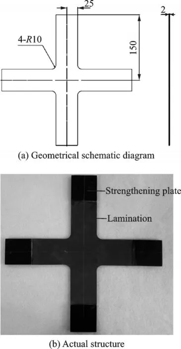
Fig.1 Specimen
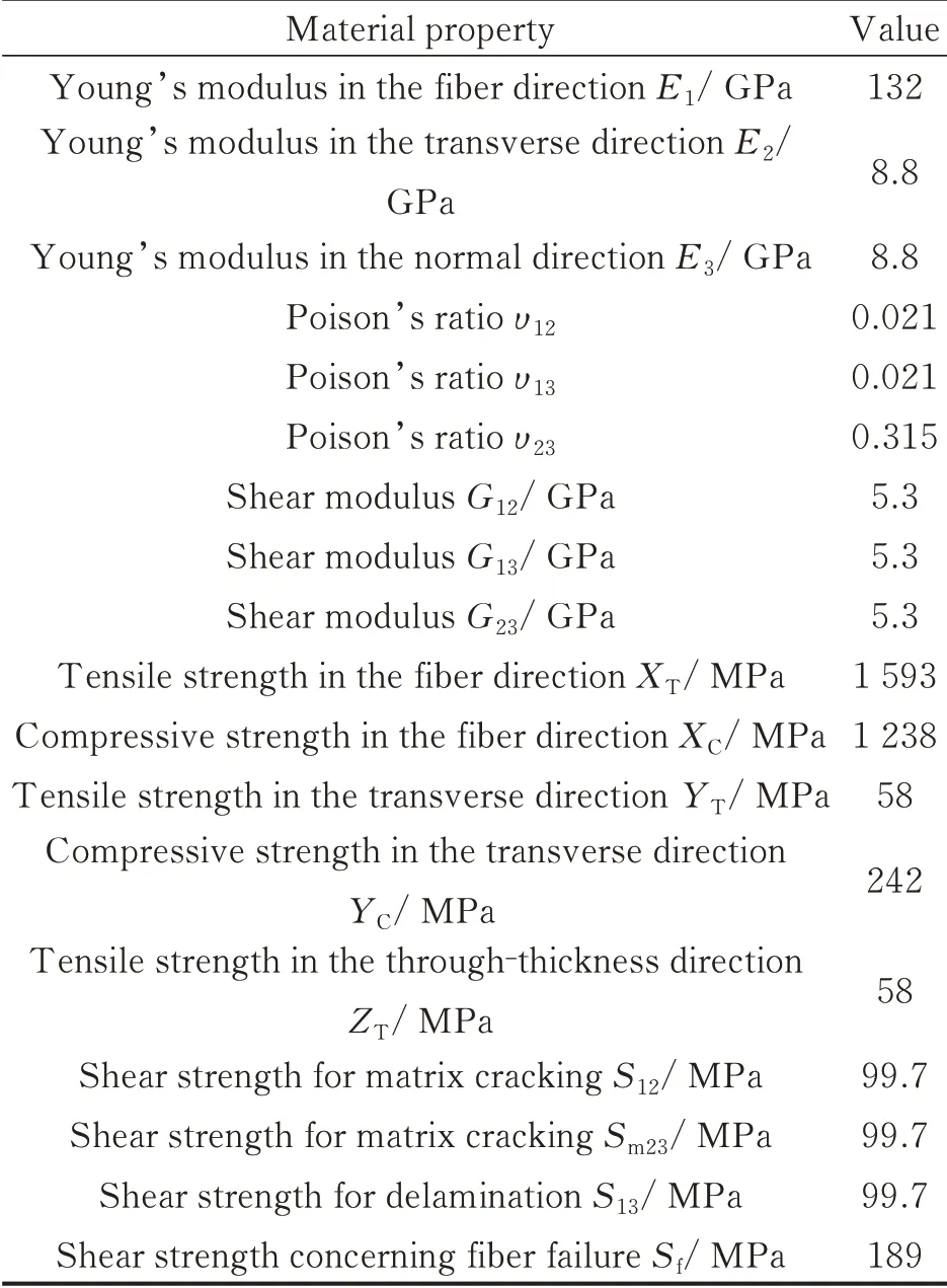
Table 1 T300 carbon-epoxy material properties
1.2 Test procedure
The specimen was clamped in the test bed of the impact testing machine KS-150LC(Fig.2),and subjected to a low-velocity impact produced by a cylindrical impactor with a hemispherical head striking the center along the vertical direction. Fig.3 shows the clamping system and shape of the impactor.
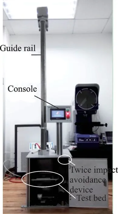
Fig.2 Impact testing machine
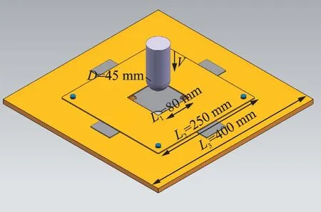
Fig.3 Illustration of the impact testing setup
Accidental handling damages such as“tool drop”often occurs during maintenance and the impact energy ranges from 10 J to 20 J. Therefore,three impact energies(10 J,15 J,and 20 J)were chosen for the impact tests. The value of impact energy was set by the console(Fig.2)in the testing machine and controlled by the guide rail(Fig.2).The initial velocity under different impact energies can be calculated by

where mI(1.5 kg)and Ei(10 J,15 J,and 20 J)represent the impactor mass and impact energy,respectively.
The specimens’numbering uses the E-Z form.E represents the impact energy and Z represents the sequence number of the specimen under the same impact energy. For example,10 J-2 presents the second specimen under 10 J impact energy.
The experimental plan consisted of two stages:
(1)Thirteen specimens were tested under three different vertical impact energies. The arrangement is shown in Table 2.

Table 2 Arrangement of specimens
(2)After the impact,the specimens were first inspected by the naked eye to observe the damage in the outer layers,and subsequently X-rayed to detect the inner damage.
2 Experimental Results
Impact damage was examined by both visual inspection and X-ray. Only the visual inspection results are shown in this section,and the X-ray results will be presented in Section 4.2.
Fig.4 shows the visual inspection of the damage for different impact energies and Table 3 presents the data for the damage size.
Fig.4 shows that(1)indentation is barely visible on the top surface for all the specimens despite different impact energies;(2)for the back surface of the specimens,fiber breaking and delamination are the primary damage forms for the 20 J impact energy while only fiber breaking is dominant for the 10 J and 15 J impact energies. Table 3 indicates that(1)the indentation depth for the three impact energies (10 J,15 J,and 20 J) ranges from 0.1 mm to 0.3 mm,suggesting no distinct difference in indentation depth among the three impact energies;(2) for the back surface of the specimens,the height of swelling(ranging from 0.1 mm to 1 mm)and the length of fiber breaking(ranging from 5 mm to 29 mm)increase with impact energy.
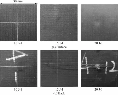
Fig.4 Visual inspection of impact damage

Table 3 Damage size of visual inspection
3 Damage Model
Based on the Hertz contact law and virtual displacement principle,the stress analysis process of laminates subjected to impact loading is derived.Further,based on the derivation results,a three-dimensional dynamic damage model,including the Hou failure criteria and Camanho stiffness degradation model,is proposed to predict the impact damage shape and area.
3.1 Analytical model
To obtain the stress distribution at every moment during the impact process,a 3D dynamic model was developed to investigate the impact dynamics.
A system consisting of a laminate and impactor is shown in Fig.5,and the origin of the coordinates is located in the middle of the short side. We assume the element displacement and stress of the laminate astuiandtσijat moment t,respectively. The equilibrium equation is given by
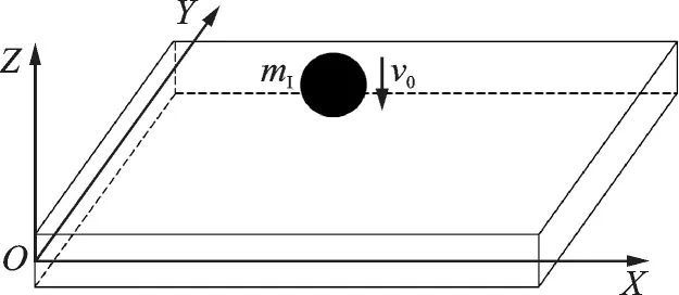
Fig.5 Coordinates of laminate and impactor

We assume that the force per unit area at the force boundary(Sσ)isat moment t,thus the force boundary condition is given by

According to the Galerkin method,the equivalent integration form combining Eqs.(2),(3)can be written as

The nonlinear geometric equation in the form of the Green strain tensor is given by

The physical equation is given by

When the angle between the fiber direction and Cartesian coordinate equals θ(shown in Fig.6),can be defined as

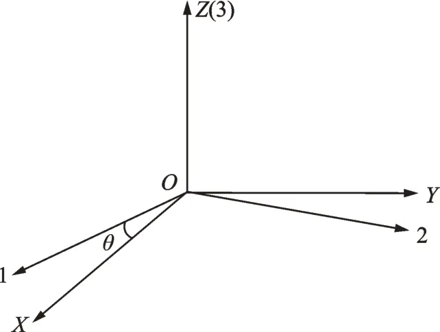
Fig.6 Angle between fiber direction and Cartesian coordinate
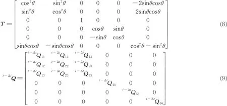
where T andt-ΔtQ represent the coordinate-transformation matrix and elastic matrix in the principal coordinate,and are given as follows
Substituting Eq.(6)into Eq.(4)yields

The element displacement is given by

where ue,ae,and N represent the element displacement,nodal displacement,and displacement shape function,respectively.
Substituting Eqs.(5),(11)into Eq.(4),we obtain the element’s equation of motion

where

Further,the laminate’s equation of motion is given by
where M,C,K,a(t),and F(t) represent the laminate’s mass matrix,damping matrix,stiffness matrix,node displacement vector,and node internal force,respectively.
The laminate’s equation of motion is obtained,and the impactor’s equation of motion can be deduced.
For the impactor,we assume the initial displacement and velocity as wI=0 andI=v0,respectively.The equation of motion is given by

where F represents the reactive force of F(t).
According to the Hertzian contact law,F can be calculated by

where k and q are constant;Fmand αmrepresent the maximum force and indentation depth during load process,respectively;α0represents the unrecoverable indentation depth;and α is a variable of the indentation depth.k and α0are expressed as follows
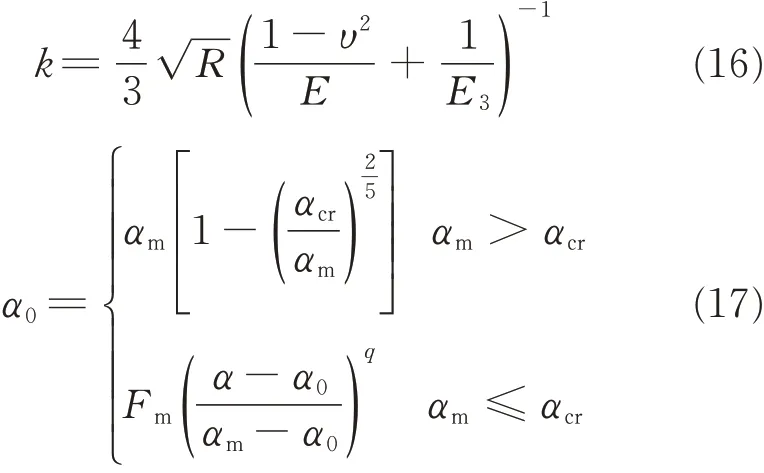
where αcris constant,R,υ,and E represent the radius,Poisson ration,and elastic modulus of the impactor,respectively,and E3represents the lamina’s elastic modulus in the thickness direction.α can be given by

where (xs,ys) is the coordinate of the contact element.
Substituting F into the laminate’s equation of motion(Eq.(13)),the nodal displacement at moment t(ae(t))can be calculated.Subsequently,substituting ae(t) into Eq.(11),the element displacement at moment t(ue(t))can be calculated.Finally,the laminate’s element strain(tε)and stress(tσ)can be obtained by substituting ue(t) into the geometric and physical equations(Eqs.(5),(6),respectively).
When the calculation is completed,the damage will be detected by the Hou[29]failure criteria. Once the damage is found,the lamina’s elastic matrix updates by the Camanho[30]stiffness degradation model,wheret-ΔtQˉijklturns intoThe laminate’s stress-strain relationship subsequently becomes

It is obvious that the laminate’s stress will change once damage occurs. Therefore,tσijwill be iterated using Eqs.(12),(5)and(19)until no damages are detected by the Hou[29]failure criteria.
3.2 Failure criteria
The Hou[29]failure criteria was employed,in which five damage modes were considered:fiber tensile breaking,fiber compressive breaking,matrix cracking,matrix crushing,and delamination.
(1)Fiber tensile failure(σ11≥0)

(2)Fiber compressive failure(σ11<0)

(3)Matrix cracking(σ22≥0)

(4)Matrix crushing(σ22<0)

(5)Delamination

where σ11is the stress in the fiber direction,σ22the stress in the transverse direction,σ33the stress in the through-thickness direction,σ12the shear stress in the plane of fiber and transverse directions,σ13the shear stress in the plane of through-thickness and fiber directions,σ23the shear stress in the plane transverse and through-thickness plane,XTthe tensile strength in the fiber direction,XCthe compressive strength in the fiber direction,YTthe tensile strength in the transverse direction,YCthe compressive strength in the transverse direction,ZTthe tensile strength in the through-thickness direction,S12the shear strength in the fiber and transverse plane,S13the shear strength in the through-thickness and fiber plane,Sfthe shear strength involving fiber failure,Sm23the shear strength for matrix cracking in the transverse and through-thickness plane,and Sl23the shear strength for delamination in the transverse and through-thickness plane.
3.3 Stiffness degradation model
To consider the stiffness degradation induced by the impact damage,the Camanho[30]stiffness degradation model was employed,as shown in Table 4.
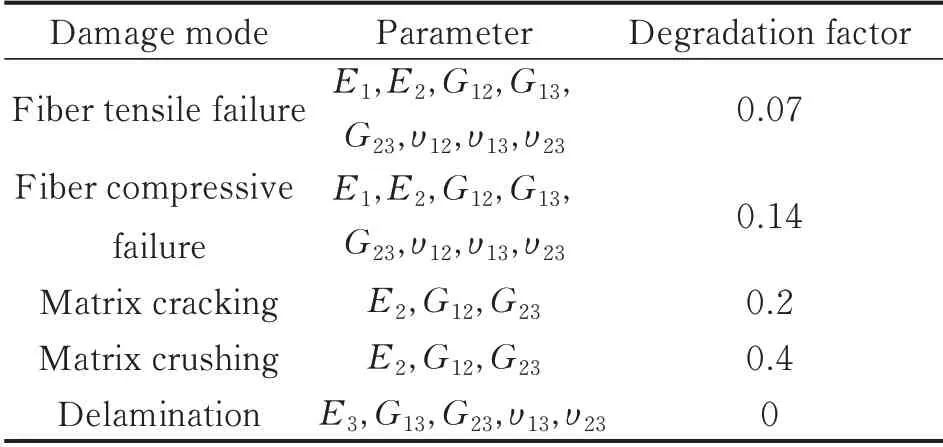
Table 4 Stiffness degradation model
4 FEM and Results
An FE was developed in ANSYS LS-DYNA based on the damage model described above,with ANSYS parametric design language (APDL).Moreover,the damage shape and area were evaluated by comparing the FEM results with X-ray results.
4.1 FE model
Solid 164 was used for the 3D modeling and this element was defined by eight nodes of the following degrees of freedom at each node:Translations,velocities,and accelerations in the nodal x,y,and z directions. To assign orthotropic material properties(listed in Table 1),the element coordinate was changed from Cartesian to principal coordinate. The impactor was modeled as a rigid body and its acceleration was assigned as g(9.8 m/s2). The impactor was placed at a small distance(h0)above the surface of the specimen and the velocity at this displacement can be calculated by

Furthermore,the analyses were performed in the nonlinear geometric behavior. Fig.7 shows the meshed modeling of the lamination and impactor.The impactor was modeled as a sphere.
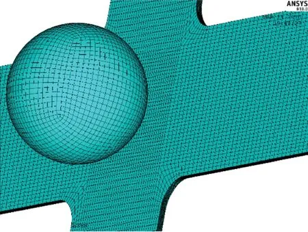
Fig.7 Meshed modeling of the lamination and impactor
First,for each element,five damage forms(including fiber tensile breaking,fiber compressive breaking,matrix cracking,matrix crushing and delamination)were detected by the Hou failure criteria (Section 3.2). Subsequently, once one of the damage forms was detected,the element was printed with the corresponding color(shown in last row of Fig.8)and its material properties were modified by the stiffness degradation model(Section 3.3).
4.2 FEM results(compared with X-ray)
Fiber breaking was evaluated by the comparison between the FEM and X-ray results,as it was the major cause of strength reduction.

Fig.8 Damage shape under three impact energies
Fig.8 shows the comparison of damage shape between X-ray results and FEM results. The X-ray result shows that despite the three different impact energies,the damage yields a shape that is similar to an ellipse. To investigate the inner damage,the total damage elements were projected on the surface lamina and the total damage is shown in second row of Fig.8. The FEM results suggest that the damage shape of fiber breaking(red and purple elements)is predicted satisfactorily.
Table 5 shows the comparison results of the damage area from the X-ray and FEM results,and Fig.9 shows the relationship between the damage area and impact energy.
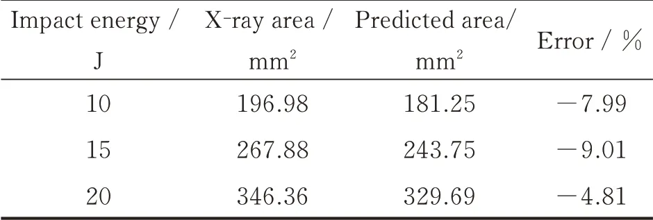
Table 5 Damage areas for X-ray and predicted results
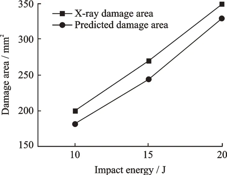
Fig.9 Relationship between damage area and impact energy
5 Damage Initiation and Propagation
Because the inner damage is difficult to detect,it is important to be able to predict the initiation and propagation for each lamina. The aim of the following sections is to investigate the damage propagation including the five damage forms using the damage model proposed above.
The initiation and propagation of the five damage forms were investigated by the FEM. For each lamina,the damage was detected with increasing contact time and the FEM results are shown in Fig.10. Because no obvious difference was found between the damage propagation under the three impact energies,the damage under 15 J was chosen as a representative. Layers 1 and 17 represent the surface and bottom laminas,respectively.
Fig.10(a)shows that when the contact time reaches 0.628 ms, damage initiation occurs,where only layers 1 and 2 exhibit fiber compressive breaking and delamination, respectively.Fig.10(b)indicates that delamination and matrix cracking occur from layers 13 to 17 at the moment t = 1.252 ms while only delamination appears in layer 12. The damage reaches the maximum at the moment t = 1.876 ms,as shown in Fig.10(c). Fig.10(c)suggests that damage has propagated in all layers,where the primary damage forms are fiber compressive breaking,matrix cracking,and delamination from layers 1 to 3,while fiber tensile breaking and delamination dominate layers 10 to 17 and only delamination in the middle layers.
Moreover,Fig.10 also indicates the following:
(1)Damage initiation occurs in the top layers and subsequently in the bottom layers. Finally,damage appears in the middle layers with damage propagation along the thickness direction.
(2) For the top layers,fiber compressive breaking is always the primary damage form during the impact process,and the damage shape is elliptical.
(3)For the middle layers,delamination and matrix cracking occur first,and fiber tensile breaking appears in the lower layers with time. Moreover,all the three damage forms are dumbbell shaped.
(4)For the bottom layers,dumbbell-shaped delamination occurs first;subsequently,elliptical fiber tensile breaking appears with time.
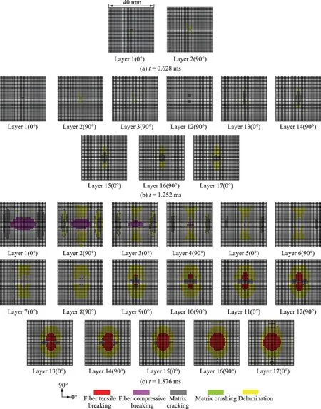
Fig.10 Initiation and propagation of five damage forms
6 Conclusions
A 3D dynamic damage model that fitted both small and large damage sizes was developed in this study to predict the impact damage initiation and propagation for each lamina of T300-carbon/epoxy laminations.
Based on the Hertz contact law and virtual displacement principle,a 3D dynamic damage model,including the Hou failure criteria and Camanho stiffness degradation model,was used to predict the impact damage shape and area. The numerical predictions of the damage shape and area indicated a relatively reasonable agreement with the experiments.
The impact damage initiation and propagation for each lamina were investigated using this damage model and the results are as follows:
(1)Damage initiation occurred in surface layers and subsequently in the bottom layers;subsequently,damage propagated in the middle layers along the thickness direction.
(2)The primary damage form was elliptical fiber breaking in the surface and bottom layers while dumbbell-shaped fiber tensile breaking and delamination dominated the middle layers.
However,some differences still existed between the numerical predictions and X-ray results,implying that it is worth refining the model further using the X-ray results for improved accuracy and increased applicability. Nevertheless,the effect of these differences on impact damage initiation and propagation must be investigated in future studies.
杂志排行
Transactions of Nanjing University of Aeronautics and Astronautics的其它文章
- Recent Advances in Hole Making of FRP/Metal Stacks:A Review
- Parameter Optimization for Improvement in Biomachining Performance
- Effect of Friction on Dynamic Response of A Power Split Transmission System
- Mathematical Model and Machining Method for Spiral Flute Rake Faces of Hourglass Worm Gear Hob
- Active Design Method of Tooth Profiles for Cycloid Drive Based on Meshing Efficiency
- Design and Study of Virtual Interventional Surgical System with Force Feedback
