Guaranteed feasible control allocation using model predictive control
2019-07-26MehdiNADERIAliKHAKISEDIGHTorArneJOHANSEN
Mehdi NADERI ,Ali KHAKI SEDIGH †,Tor Arne JOHANSEN 2
1.Center of Excellence in Industrial Control,Faculty of Electrical Engineering,K.N.Toosi University of Technology,Seyyed Khandan Bridge,Shariati Ave.,Tehran,Iran;
2.Center for Autonomous Marine Operation and Systems,Department of Engineering Cybernetics,
Norwegian University of Science and Technology,N7491,Trondheim,Norway Received 2 September 2017;revised 25 October 2018;accepted 21 February 2019
Abstract This paper proposes a guaranteed feasible control allocation method based on the model predictive control.Feasible region is considered to guarantee the determination of the desired virtual control signal using the pseudo inverse methodology and is described as a set of constraints of an MPC problem.With linear models and the given constraints,feasible region defines a convex polyhedral in the virtual control space.In order to reduce the computational time,the polyhedral can be approximated by a few axis aligned hypercubes.Employing the MPC with rectangular constraints substantially reduces the computational complexity.In two dimensions,the feasible region can be approximated by a few rectangles of the maximum area using numerical geometry techniques which are considered as the constraints of the MPC problem.Also,an active MPC is defined as the controller to minimize the cost function in the control horizon.Finally,several simulation examples are employed to illustrate the effectiveness of the proposed techniques.
Keywords:Control allocation,feasible region,actuator constraints,model predictive control
1 Introduction
Many safety critical systems such as aircrafts[1],ships and underwater vehicles[2]are designed with redundant effectors and actuators.This redundancy could be employed in order to meet a secondary objective such as power consumption optimization,maneuverability,and fault tolerance.Control allocation is an approach to manage actuator redundancy under various conditions.The prime objective in a control allocation technique is to produce a desired total control effect computed by the system controller from a set of redundant actuators such that the actuators’constraints are satisfied[3,4].
In the last two decades,several methods have been proposed for the control allocation problem.Most of the proposed schemes follow a modular control configuration program which divides the control systems structure into the following two parts:The main controller that provides the specified desired total control effort(also called the virtual control signal)and the control allocator unit that maps the total control demand onto individual actuator settings.The simplest control allocation scheme is the pseudo inverse approach to distribute the virtual control signal among the available actuators[4].The main drawback of the basic pseudo inverse approach is the fact that the actuators constraints can be easilly violated.
The advanced techniques based on the pseudo inverse concept attempt to resolve this problem.These include the redistributed pseudo inverse method,the daisy chain scheme,the pseudo inverse correction along the null space,and the direct allocation method[4].Basically,the pseudo inverse solution is calculated first and if this solution satisfies the actuators constraints,no further steps are needed.Otherwise,different remedies are proposed to solve the constraints violation problem.In the redistributed pseudo inverse method,the control signal vector is partitioned into the saturated,and unsaturated elements and the unsaturated elements are recomputed by solving a reduced problem using the reduced pseudo inverse to compensate for the saturation effects on the virtual control signal.The redistribution procedure is repeated until either the desired virtual control signal is generated or no improvements are achieved in the process continuation[4,5].In the daisy chain scheme,actuators are divided into several groups.Initially,control signals of the first actuators group is calculated using the reduced pseudo inverse.If the first group of actuators could produce the desired virtual control,next groups remain unused.Otherwise,the second group of actuators is employed to generate the remaining virtual control demand.This procedure is repeated until either the virtual control signal is satisfied or all of the actuator groups have been employed[6,7].Tohidi et al.[8]proposed an algorithm to modify the pseudo inverse solution using the null space.This approach is based on the fact that each member of the null space of the control effectiveness matrix could not affect the virtual control signal whereas it could modify the control signal vector.In this method,a vector of the null space is added to the pseudo inverse solution if the solution does not satisfy the constraints.The corrective term is calculated such that elements of the control signal which violate the constraints are forced back to the admissible region.Zhi et al.[9]presented a robust adaptive fault tolerant control using a wieghted pseudo inverse control allocation in the presence of disturbance,unmodeled dynamics and actuator nonlinearity.The main controller is a combination of an adaptive control,radial basis function neural network,and a robust controller.Although the above mentioned methods are fast and rather effective,they do not guarantee a feasible solution for the control allocation problem,even when one exists.
The direct allocation approach is a constrained control allocation approach based on scaling of the unconstrained problem solution.When the pseudo inverse solution violates the actuators’constraints,another virtual control signal with the same direction and a smaller norm is applied to the system such that the control signal is located in the attainable space[10,11].This method changes the desired total virtual control which may lead to performance and stability degradations.
Iterative methods are also widely employed to solve the control allocation problem.Linear and quadratic programming approaches are proposed as control allocation methodologies.These methods convert the control allocation problem to the standard optimization formats and consider actuators constraints.These methods minimize a selected linear or quadratic cost function to minimize the difference between the produced virtual control and its desired value[12-14].Linear and quadratic programming techniques have been used to manage actuator constraints in many applications[15-17].Rajput et al.[18]considered interaction between actuators and proposes the control allocation problem as a mixed optimization problem.
In addition,some integrated methods are proposed for control allocation which concurrently analyse the main controller and the control allocator unit.Fault tolerant control scheme using on-line control allocation based on various types of sliding mode control concepts are presented in[19-24].They develop a rigorous design procedure from a theoretical view and prove closed loop stability in the presence of some bounded uncertainties.Ji et al.[25]presented the standard H-infinity criterion to minimize the control effort and the virtual control error.The integrated methods do not consider actuators constraints explicitly in their design.
Control allocation has a growing application in a wide range of systems.Recently,it has been employed in unmanned aerial vehicles(UAV)[26],neuroprosthesis[27],and electric vehicles[28].
In this paper,to achieve feasibility,actuator constraints are included in the control design through a feasible region determination procedure that simultaneously benefits from the modular and integrated control allocation strategies.The control allocator unit finds the feasible region in the virtual control space.The idea proposed in this paper is to consider the feasible region as the constraints of a set of MPC problems which produce the desired virtual controls.Generally,the feasible region could be considered as polyhedral constraints.The feasibility consideration guarantees generation of a desired virtual control which maintains systems stability and performance.
It is possible to replace a polyhedral by its approximation which includes a few axis aligned hypercubes.The set of employed model predictive controllers consider the control allocation feasible regions in the approximated hypercubical form as their control signal constraints,and produce the desired virtual control to satisfy the corresponding constraints.This reduces the computational complexity of the MPC problems,but may require the solution of several MPC problems to achieve an accurate approximation.In this paper,the two dimensional case is studied in detail and two algorithms are employed to find the largest rectangle in the feasible region.
The paper is structured as follows.The problem statement is given in Section 2.Section 3 presents the proposed methods to design the guaranteed feasible control allocation using the MPC approach.In Section 4,simulation results are illustrated to show the performance of the proposed scheme.Concluding remarks are given in Section 5.Also,two algorithms are outlined for finding the maximum area rectangle in a polygon in the appendix.
2 Problem statement
Consider a linear system described by the following discrete time state-space equations:


The virtual control signal is the total effect of the inputs and it is introduced as follows:

where B ∈Rd×mis called the control effectiveness matrix which is derived from the system structure and is related to the effectors type,size and location.Combining(1)and(3)yields the following state space representation:

and Bvsatisties

The admissible space can be defined as follows:

where the constraints boundsanddepend on the respective actuator health and status.
Control system is divided into two parts,the main controller and the control allocator unit.The main controller produces the desired virtual control signal in order to meet the primary closed loop specifications such as stability,set point tracking and disturbance rejection.The control allocator unit maps the desired virtual control to the actuators commands.It is assumed that the actuators are static and if their commands are admissible with respect to their constraints,u(t)will equal to its command.
3 The guaranteed feasible control allocation methodology
This paper proposes a control allocation scheme which employs the model predictive controllers to guarantee that the desired virtual controls are generated such that the actuators command are admissible.
3.1 Determining the feasible region
The first step of the method is to determine the feasible region in the virtual control space.
Definition 1Feasible region is a subset of the virtual control space.If the desired virtual control signal is located there,it is guaranteed that the control allocation unit will map it into the control signal space such that actuator constraints are not violated.
Let B†denote the pseudo inverse of the matrix B:

where WIis a weighting matrix which could be the identity matrix in particular.The solution of the control allocation problem using the pseudo inverse is

where vdis the desired virtual control.To determine the feasible region,the following inequalities,which define a convex polyhedron should be satisfied:

where fiis the ith row of F.There are numerous softwares to show the polyhedral in both hyper plane and vertex representations such as CDD and the multi parametric toolbox(MPT)[29].For the two dimensional virtual control space,the admissible solution for each inequality is a space between two parallel lines denoted by si1and si2which is defined as follows:


where i,j=1,2,...,m,i ≠j and k,l=1,2.
In what follows,the algorithm for determining the feasible polygon region for a two dimensional space is given.
Algorithm 1The procedure of determining the feasible region could be expressed as follows:
▪Consider the 2m lines given by equations si1and si2as(10).
▪Determine the intersection points as(11).
▪Find the intersection points satisfying(9)for all 1 ≤i ≤m.
▪The polygon whose vertices are the points found in the third step is the feasible region.
Fig.1 shows the feasible region of a given B matrix and the actuator constraints.
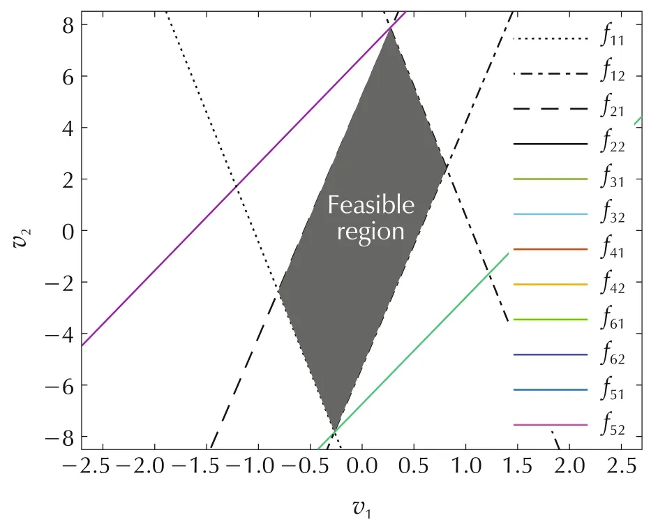
Fig.1 The feasible region.
3.2 Feasible control allocation using the MPC controller with the polyhedral constraints
If the desired virtual control vector is in the feasible region,the pseudo inverse solution directly gives the actuators commands.Therefore,the main controller should produce the desired value of the virtual control signal located in the feasible area.The first strategy is to employ an MPC controller which could consider inequalities shown in(9)as its input constraints.The MPC controller minimizes the following cost function[30]:
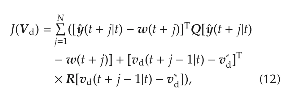
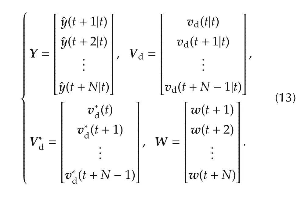
The predicted states can be rewritten as Y=Hx(t|t)+SVdwhere
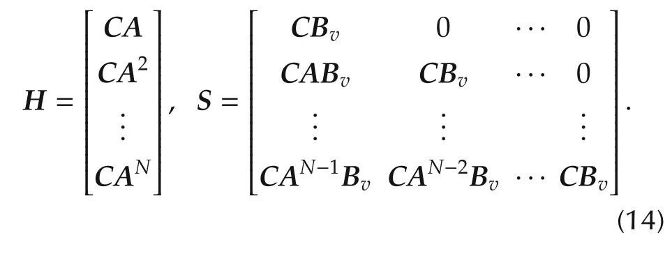
Hence,the cost function can be written as follows:


3.3 Feasible control allocation using the MPC controller with rectangular constraints
Considering the constraints as(16)may lead to a large computational burden.Replacing the feasible region polyhedral by an approximated axis aligned hypercube can reduce the number of constraints and make them simpler and reduces the computational time.In the two dimensional virtual control space,the feasible region could be approximated by an axis aligned rectangle.It is possible to employ the algorithms of finding the maximum area rectangle in a polygon described in the appendix.The derived rectangles based on the algorithms mentioned in the appendix are shown in Fig.2.Note that the area of the second and fourth derived rectangles equal to zero.
One conservative strategy is to consider the largest rectangle among the four rectangles which are found based on the algorithms mentioned in the appendix as the control signal constraints of an MPC controller.The MPC controller solves the following optimization problem where the cost function is defined as(15):

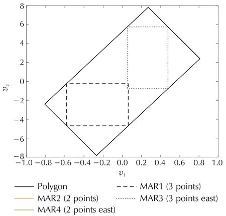
Fig.2 Maximum area rectangles in the feasible region.
Algorithm 2The following steps are proposed to implement the feasible control allocation based on the MPC controller:
▪Determine the feasible region of the control allocation problem.
▪Find the largest axis aligned rectangle inscribed in the feasible polygon region.
▪Design the MPC controller constrained by the control signal within a given rectangle.
▪In each sample time:
a)Calculate the desired virtual control signal using the MPC strategy.
b)Map the desired virtual control to the actuator commands using the pseudo inverse(7)and(8).
It should be noted that the first three steps are executed only for initialization.
3.4 Feasible control allocation using the multiple MPC controllers
In Fig.2,it can be clearly observed that by selecting any rectangle,a significant part of the feasible polygon region will be neglected.This problem could decrease the controller performance due to the virtual control signal being too restricted.In order to enlarge the covered area of the feasible region approximation,a multiple MPC strategy is proposed,where each calculated rectangle is considered as the constraints of a separate MPC controller.Therefore,a larger area within the polygon region will finally be covered.Plant dynamics and cost function parameters remain unchanged while the control signal constraints are derived from the determined rectangles for l=1,2,...,Nr.Each controller solves an optimization problem as follows[30]:

Algorithm 3The following steps are performed to implement the feasible control allocation methodology based on the multiple MPC controller strategy:
▪Determine the feasible region of the control allocation problem.
▪Find Nraxis aligned rectangles in the feasible polygon region.
▪Design NrMPC controllers by the control signal constraints defined by the rectangles.
▪In each sample time:
a)Calculate the desired virtual control signal and the cost function of each MPC controller.
b)Select the best virtual control which has the minimum cost function.The controller is switched only if the new active controller improves the cost function value with the hysteresis parameter h.Also,the selected controller remains active for at least τdtime units.
c)Map the chosen desired virtual control to the actuator commands using the pseudo inverse(7)and(8).
Structure of the proposed algorithm is shown in Fig.3.The switching control supervisor unit selects the active controller by considering the dwell time and the hysteresis.Also,the feasible control allocation unit determines the feasible region and introduces the corresponding rectangles to the MPC controllers for constraints generation.The computation time can be reduced since the MPC controllers can be evaluated in parallel simple box constraints.
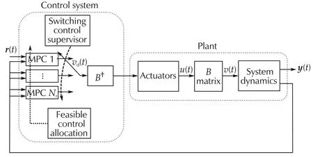
Fig.3 Structure of the feasible control allocation using the multiple MPC strategy.
4 Simulation results
In this section,simulation results are presented to show the effectiveness of the proposed methodologies.The CVX toolbox[32]is employed to solve the optimization problems.
4.1 Example 1
In this example,the following methods are employed for a comparitative study:
1)The feasible control allocation(FCA):An MPC controller is employed as the main controller that considers the feasible region as the polyhedral input constraints.
2)MPC with PAN:An unconstrained MPC and the pseudo inverse along the null space(PAN)methodology[8]are used as the main controller and the control allocator unit,respectively.
3)MPC with quadratic programming(QP):An unconstrained MPC and the quadratic programming strategy are used as the main controller and the control allocator unit,respectively.
4) LQ with quadratic programming: A linear quadratic(LQ)optimal control and the quadratic programming strategy[13]are used as the main controller and the control allocator unit,respectively.
5)LQ with RPI:A linear quadratic(LQ)optimal control and the redistributed pseudo inverse(RPI)strategy[5]are used as the main controller and the control allocator roles,respectively.
Consider the following linearized state space model[33]:
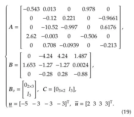
Under the given condistions,the different methods have a similar performance and they appropriately manage the actuators.As is shown in Table 1,employing the LQ controller instead of the MPC decreases the computational burden significantly.In order to quantitatively compare the results,Table 1 presents the computational time and the cost function value for the methods.The cost function is defined as follows:

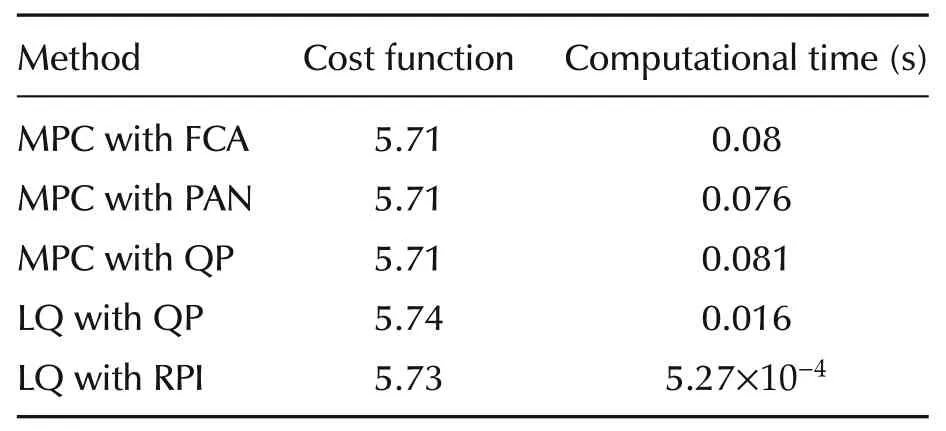
Table 1 Example 1:Methods comparison.
In the next simulation,the upper and lower bounds of the 4th actuator are tightened(e.g.,due to the actuator fault)as follows:
In this case,closed loop systems which do not consider the feasibility concept became unstable.Instability has occurred due to the discrepancy between the desired and the actual virtual control signals which appeared because of lack of feasibility consideration.As is shown in Fig.4,using the feasible control allocation preserves closed loop stability and only the transient performance is degraded.There is no discrepancy between the desired and the actual virtual control signals as shown in Fig.4(b)Hence,it is observed that using the feasible region information in the main controller could extend the stability region and achieve a better performance.
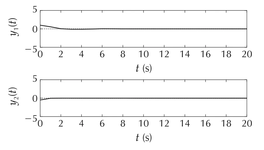
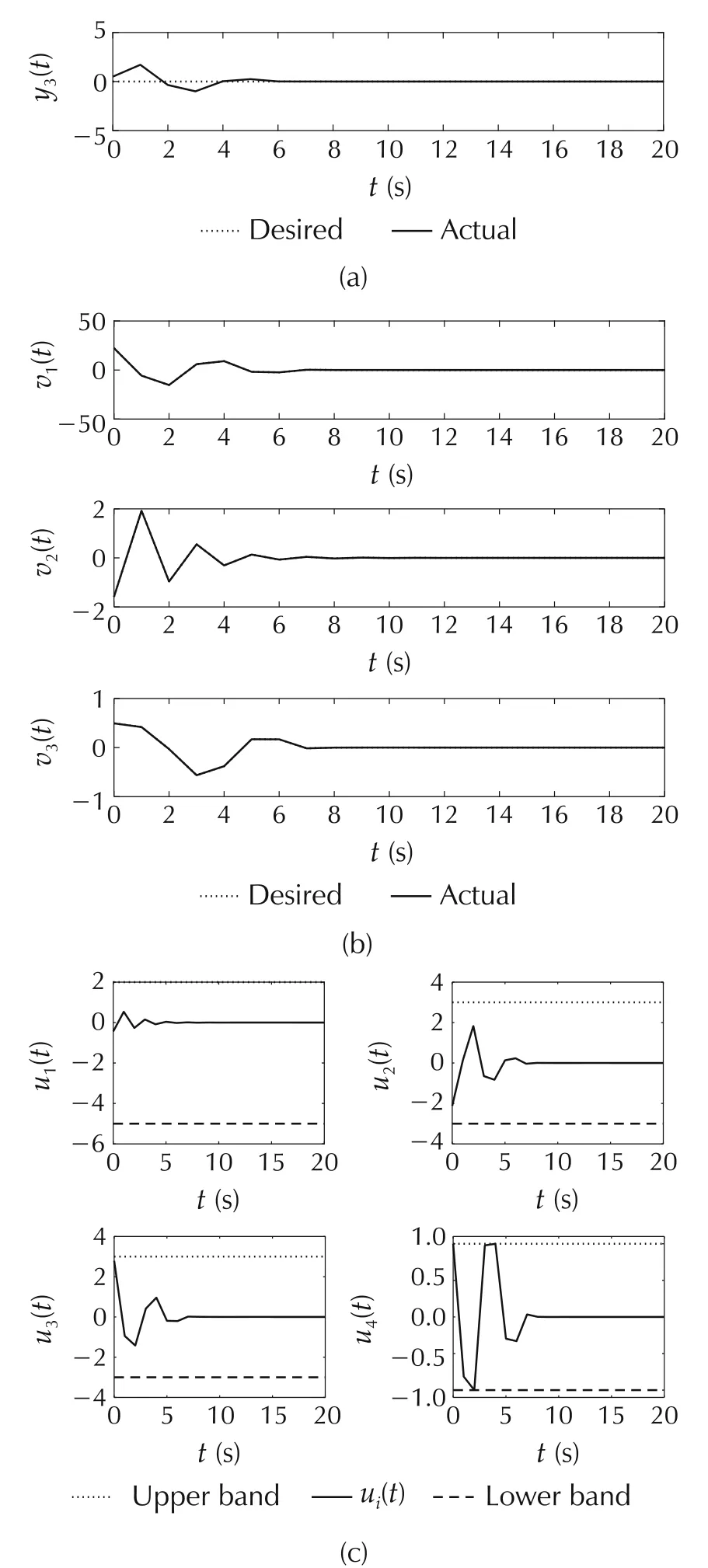
Fig.4 Example 1:The feasible MPC method.(a)System outputs.(b)Virtual control signals.(c)Control signals.
4.2 Example 2
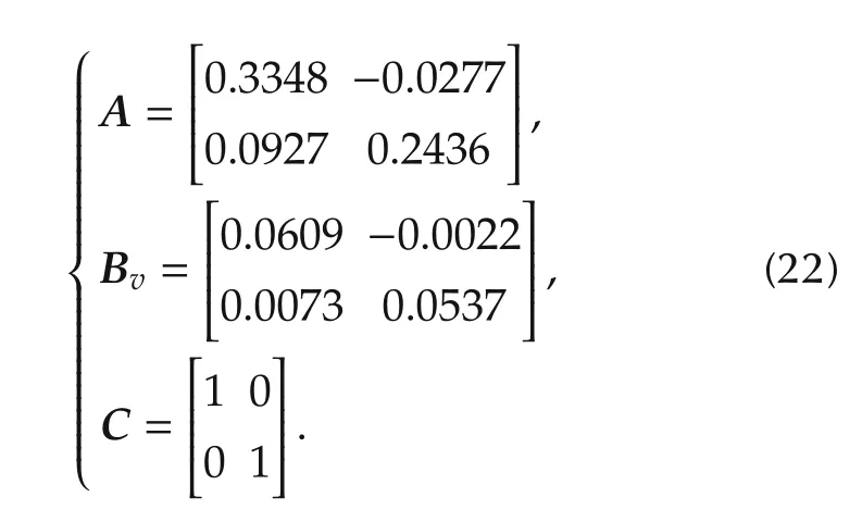
In the second example,three methods are employed for comparison study:1)feasible control allocation using the MPC controller with polyhedral constraints,2)feasible control allocation using the single MPC controller with rectangular constraints,and 3)feasible control allocation using the multiple MPC controllers with rectangular constraints.Consider the following linear model of an electric vehicle[34]:
Also,the control effectiveness matrix and the actuator upper and lower limits are as follows:
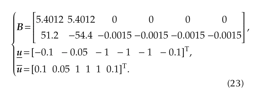
Fig.5 depicts the results of employing the feasible control allocation using an MPC controller with the polyhedral constraints.As is shown in Fig.5(a),this scheme leads to the desired transient and steady state responses.Also,there is no discrepancy between the desired virtual and actual control signals as shown in Fig.5(b).
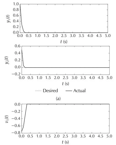
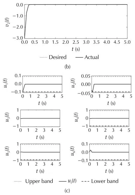
Fig.5 Example 2:The feasible region method using an MPC controller with polyhedral constraints.(a)System outputs.(b)Virtual control signals.(c)Control signals.
For the feasible control allocation with a single MPC controller,the largest rectangle found in the feasible region of this example shown Fig.2 is considered as the constraints of an MPC controller.It is obvious that a large area of the feasible region is ignored by considering only the largest rectangle and it causes steady state error in the second output as is depicted in Fig.6(a).A particular problem is that positive values of the desired virtual control signals are strongly restricted as is shown in Fig.2.Note that it could be seen in Fig.6(b)that the generated and the desired virtual signals are identical which is due to applying a part of the feasible region as the input constraints of the MPC problem.
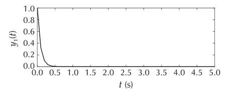
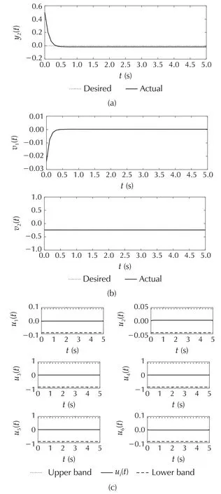
Fig.6 Example 2:The MPC controller method.(a)System outputs.(b)Virtual control signals.(c)Control signals.
For the multiple MPC controller scheme both rectangles shown in Fig.2 are considered.Results of applying multiple control with the dwell time are shown in Fig.7.As is seen in Fig.7(a),enlarging the feasible region by considering two rectangles improves the control performance.Also,the difference between the virtual and actual control signals equals zero.The active controller is switched when it is necessary,as is shown in Fig.7(d).Table 2 shows the average running time of the proposed methods to compare their computational burden.Using the multiple MPC controller scheme with rectangular constraints which employs parallel processing decreases running time of the control procedure in each sample time while it does not cause an unacceptable performance.It should be mentioned that the computational times are presented only for comparison and they can be decreased substantially in real time implementations.
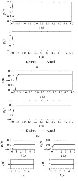
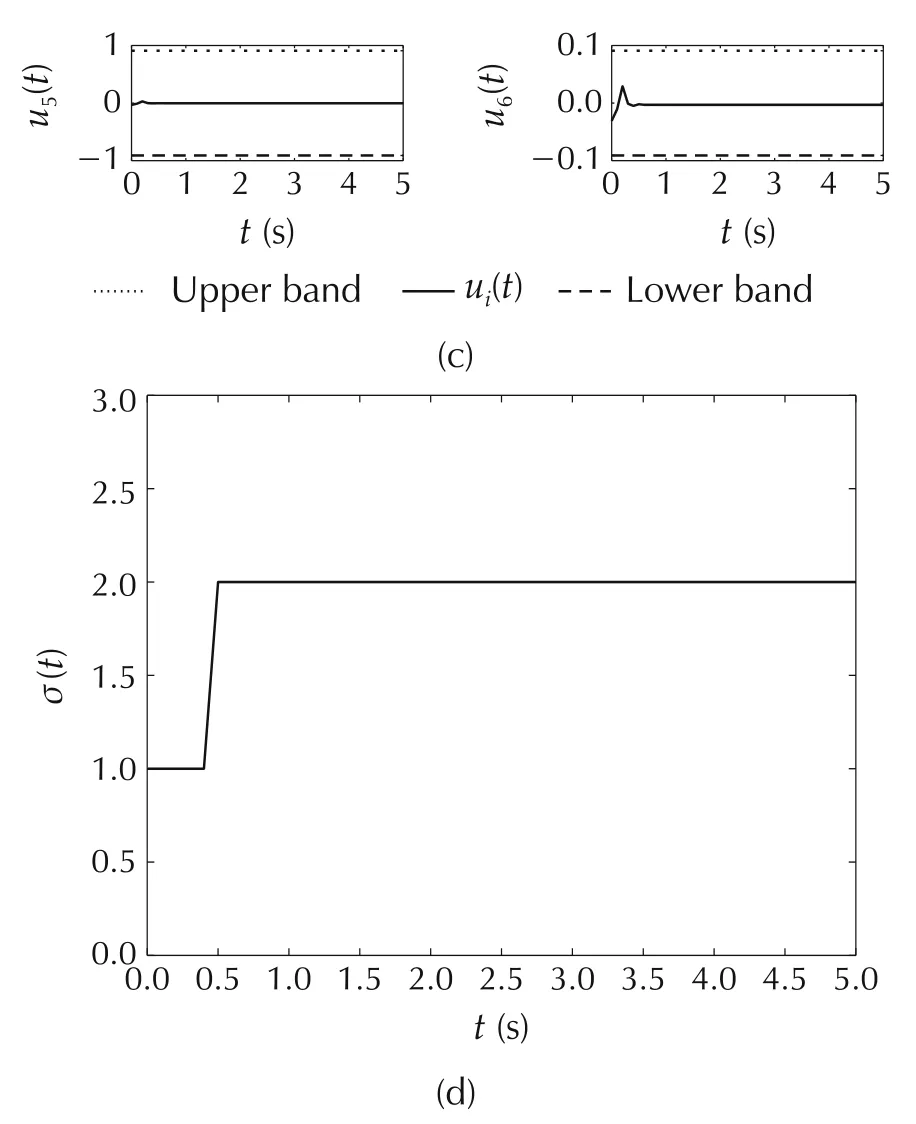
Fig.7 Example 2:The multiple MPC controllers method.(a)System outputs.(b)Virtual control signals.(c)Control signals.(d)Switching signal.

Table 2 Comparison of the running time of the presented methods.
5 Conclusions
This paper proposes a guaranteed feasible control allocation methodology.The feasible region is determined by characterizing the polyhedral feasible region of the pseudo inverse solution.Then,the feasible region is introduced to the main controller as the constraints of an MPC problem.Another approximated method is presented for decreasing computational time where several axis aligned hypercubes are considered as an approximation of the feasible region.A set of MPC controllers solved using parallel processing are employed as the main controllers where each of the given hypercubes is considered as constraints in the corresponding MPC controller.Then,switching control is used to choose the most appropriate controller in each step having the lowest cost and satisfying dwell time specifications.In the case of two dimensional virtual control space,an algorithm is employed to find the maximum area rectangles inscribed in the feasible polygon region.Simulation results are used for comparison studies and to show that computational cost can be reduced with the approximate method.
Appendix
a.The maximum area rectangle principle
In the two dimensional virtual control space,the feasible region can be generally characterized by a convex polygon.To develop a guaranteed feasible control allocation strategy with lower computational complexity,a maximum area rectangle(MAR)which lies in the convex polygon of the feasible region is identified.To derive this MAR the algorithm developed in[35]is employed.This mathematical algorithm has been used in several engineering applications such as the wireless sensor network[36].The algorithm takes the polygon vertices and yields an axis-aligned rectangle in the polygon which has the maximum area.To briefly present the MAR algorithm,some basic definitions are given below.Consider Q,Q′∈R2,Q=(x,y),Q′=(u,v)with x <u and y <v.Then R=Rect(Q;Q′)is the rectangle with the lower left corner given by Q and the upper right corner given by Q′.Area of the rectangle is denoted by area(R)=(u-x)(v-y).Let P be a bounded convex polygon with n vertices and denote its boundary by δP.Also,the corners of a rectangle indicated by the lower left,lower right,upper left and upper right are denoted by LL(R),LR(R),UL(R)and UR(R),respectively.Also,the southeast,southwest,northeast and northwest parts of the polygon are denoted by SE,SW,NE,and NW,respectively.Note that the four parts are not necessarily disjoint.The maximum area rectangle could have two or three corners on δP,and two separate algorithms are presented in[35]to find the above two possible rectangles.
a1.MAR with at least three vertices on the boundary
Let xlbe the minimum x-coordinate of a vertex of P.Consider xNW(xSW)as the maximum x-coordinate of a vertex on NW(SW),and xr=min(xNW,xSW).Let S(x)be the vertical line at x,xl≤x ≤xr,and let y1and y2be the y-coordinates of the intersections of S(x)and P.Consider uias the xcoordinate of the horizontal projection of yionto NE ∪SE,i=1,2.Define x′=min(u1,u2).Also,consider the rectangle R(x)=Rect((x,y1),(x′,y2)).
Definition a1A function f(x)is called almost strictly bitonic on[xi,xj],if there exist xk,xm∈[xi,xj]such that f(x)is strictly increasing on[xi,xk],strictly decreasing on[xm,xj]and constant on[xk,xm].
Theorem a1area(R(x))is continuous and almost strictly bitonic on[xl,xr].
Algorithm a1The procedure of finding the maximum area rectangle with at least 3 corners on the boundary of the polygon is summarized as follows:
▪Find that vertex(x1,y1)of SW which halves SW with respect to the number of vertices and its right neighbour(x2,y2).
▪Compute the corresponding rectangle R(x1),R(x2)and determine the following alternatives:
a)If area(R(x1))>area(R(x2)),then search should be followed in[xl,x2].
b)if area(R(x1))<area(R(x2)),then search should be followed in[xl,xr].
c)if area(R(x1))=area(R(x2)),then iteration should be stopped.
▪If only two adjacent vertices of SW are left,a binary search should be done.
a2.MAR with two vertices on the boundary
Consider the maximum area rectangle M that has exactly two diagonally opposed corners on δP.Only the cases that LL(M)∈SW and UR(M)∈NE will be discussed here.Let xland xrbe defined as above,x ∈[xl,xr]and(x,y)be the projection of x onto SE.Then,MR(x)is the maximum area rectangle(not necessary included in P)with lower left corner(x,y)and upper right corner on NE.
Theorem a2[35] area(MR(x))is continuous and almost strictly bitonic on[xl,xr].
Algorithm a2[35] The procedure of finding the maximum area rectangle with exactly two corners on the boundary of the polygon is summarized as follows:
▪Find x as the x-coordinate of that vertex which halves[xl,xr]with respect to the number of vertices on SW.
▪Compute MR(x)by a binary search on NE.
▪If both UL(MR(x))and LR(MR(x))are outside of P,stop the algorithm.Because it is proved that no MR(x′)could be found such that it is totally contained in P,for any x′∈[xl,xr].
As indicated in Algorithms a1 and a2,two rectangles could be obtained which have a corner on SW.According to the algorithms,it is possible to determine another two rectangles that their lower right corners are located on SE.It should be noted that some of these rectangles could have zero area.
杂志排行
Control Theory and Technology的其它文章
- Parallel loop recovery with quiescent compensation for high performance feedback control of systems with imperfect actuators
- Nonlinear observer-based control design and experimental validation for gasoline engines with EGR
- Invariant observer design of attitude and heading reference system
- On the mechanism and control for the ultra-low frequency oscillation in NY Power Grid with large-scale hydropower
- Diagnosability of a class of discrete event systems based on observations
- Optimal finite-dimensional spectral densities for the identification of continuous-time MIMO systems
