Parallel loop recovery with quiescent compensation for high performance feedback control of systems with imperfect actuators
2019-07-26BRIENBRIEN
Y.V.O’BRIEN,J.F.O’BRIEN
Department of Electrical and Computer Engineering,University of Wyoming,Laramie,WY 82073,U.S.A.
Received 23 February 2018;revised 29 September 2018;accepted 8 October 2018
Abstract Actuator limits and imperfections introduce multiple nonlinearities in a feedback loop.While standard mild-feedback systems(e.g.,PID)are intrinsically robust to such nonlinearities,the stability of large feedback systems is threatened.This eliminates from consideration the usage of imperfect actuators in large feedback applications and available disturbance rejection as a result is not realized.The implementation of multiple-path nonlinear dynamic compensation(NDC),however,allows the combination of large feedback and imperfect actuation and is the focus of this work.As nonlinearities due to actuator imperfection are often difficult to model,the stability of the NDC systems is assessed using multivariable absolute stability analysis.The features of a parallel loop recovery system with loop transmission modulus reduction compensation in the quiescent condition are compared to an alternative approach of strict modulus reduction via nonlinear compensation for stability retention.Efficacy of the loop recovery approach is illustrated using experimental data from a voice-coil actuated disturbance rejection system.
Keywords:Feedback control,imperfect actuators,nonlinear dynamic compensation
1 Introduction
Large feedback control systems require accurate plant models for purposes of design.While large feedback has the effect of reducing sensitivity to small parameter variations in the actuator,nonlinearities such as those found in inexpensive actuators affect changes in loop gain that threaten stability.This is an unfortunate limitation,as cheaper actuators are typically more rugged than their expensive counterparts and are more suited to military applications where large disturbance rejection is often required.A method for large feedback control applied to quasi-linear plants is presented.Such plants are characterized by disjoint input intervals where superposition fails.Inside these intervals nonlinear features govern the response.These nonlinearities can be classified as limit nonlinearities such as actuator saturation,and imperfection nonlinearities,commonly friction/stiction nonlinearities in moving parts of a mechanical system.When there are variations in loop gain and phase which these nonlinearities produce,high performance linear controllers designed for large feedback will oscillate.To satisfy the high performance requirement,conventional methods of improving robustness such as bandwidth reduction and shallow loop transmission roll-off are not applicable.Instead direct compensation of the effects of these nonlinear features in the high performance controller design is prudent.
The area of constrained control is well researched,yet most attention is given to the issue of wind-up in saturated loops with integral action.An ample overview of the anti-windup control problem in both its previous and subsequent alternatives is given in[1,2].In these papers the connection between anti-windup control and stabilizing control to satisfy the absolute stability condition is established.Contemporary anti-windup theory can be described as the application of modern and robust control theory to the constrained problem[3,4]and[5,6].A control architecture that trades high performance for increased robustness in saturation is presented in[7].Stability of feedback controllers applied to systems with hard or limiting nonlinearities confined to sectors can be assessed using absolute stability theory[8,9].A Popovlike criterion is used in a control design for a system with non-collocated actuators and friction in[10].Nyquiststable control applied to the spaceborne interferometer pathlength regulation problem is described in[11,12].Nonlinear dynamic compensation with multiple feedback paths is applied to a marine autopilot with steep loop transmission roll off and multiple actuator saturations in[13,14].In an aggressive feedback system such compensator is used to smoothly vary loop transmission in order to retain stability.Its implementation is similar to variable gain control approach to adjust loop transmission as a function of disturbance-driven error.A variable gain scheme is applied to optical disk drives in[15],and facilitates a smooth transfer of loop gain between channels of a single-input/two-output wind turbine rate regulator in[16,17]and also in[18].
There is a long history in the study of controlled systems with friction;comprehensive analysis is found in[19,20]and in[21,22].In specific cases the effect of friction is well known,however a general theory explaining all friction phenomenon has yet to be developed[23].One of the earliest investigations of servomechanisms with friction uses describing function analysis[24].The results demonstrate that friction imposes limitations on the amount of feedback available with linear control.A closed-loop system response shows limit cycle oscillations when a more aggressive controller is applied.An algebraic analysis in[25]finds that PID control of systems with certain friction nonlinearities,minimal Coulomb and nonzero static frictions also exhibits limit cycling.Control application to compensate this nonlinear behavior is desired in order to ameliorate negative effect of friction on system response.Several nonlinear modifications to PID control and adaptive control strategies to compensate for friction are described in[20].PID,PID with dithering,and three adaptive controllers using different friction models are implemented and compared to conclude that the Dahl model is the most suitable.A learning control scheme to track trajectories in mechanical systems with friction is discussed in[26].A method of adaptive nonlinear friction compensation is presented in[27].The design is a PD controller with reversed position-error integral control proving to be effective at compensating for Coulomb-like friction in a 6-degrees of freedom(6-DOF)manipulator.The friction model of[19]is utilized in a PID control scheme for a second order mechanical system with perfect knowledge in[28].To compensate for Coulombic friction in single DOF mechanical system with friction an adaptive control method is used in[29].Adaptive friction compensation is applied using extended Kalman-Bucy filter friction estimation to a simple rotary plant in[30].Sliding-mode control has been used on a second-order mechanical systems with friction[31,32].Simulation results show accurate tracking of sinusoidal signal of a flight simulation table in a noiseless environment.To reduce stack overflow in hysteresis force application modifications to the Leuven friction and Maxwell slip models are made in[33].High performance motion tracking feedforward control of the art laser processing system for electronics manufacturing is experimentally researched in[34].A controller is designed using an approximate nonminimum-phase LTI model of the closedloop plant,inverse dynamics control,an adaptive FIR filter,and an iterative learning control algorithm.A wide variety of research done in the area implies a canonical set of friction models for control applications does not yet exist.Furthermore,these approaches for modeling and control of plants with friction are developed for low performance improvements in small disturbance environments,and are ill-suited for aggressive controllers subjected to large disturbance power.
An approach that employs nonlinear dynamic compensation(NDC)with multiple feedback paths to allow the stable application of large feedback despite multiple loop nonlinearities is presented in[35,36].While the work focused on smooth transitions of transmission to loop shapes that satisfy the conditions of absolute stability,the notion of using nonlinear compensation to increase loop modulus to reestablish the aggressive shape designed for nominal operation was introduced.This approach does not compromise feedback applied over the functional bandwidth in the nominal disturbance environment,however initial experiments showed that this method of nonlinear compensation produced excessive positive feedback in the neighborhood of crossover.Such a limiting feature of the gain-increasing nonlinear compensation scheme is considered by authors a potentially unacceptable.
The parallel loop recovery(PLR)system for nonlinear loop transmission reintroduction with acceptable positive feedback is presented in this paper.It is shown that the decomposition of the low amplitude input subdomain into intervals for individual nonlinear compensation designs provides the necessary design degrees-offreedom for the accurate reshaping of the loop transmission.The PLR system is augmented with quiescent compensation to further improve response characteristics when operating in very low disturbance power conditions where loop modulus augmentation is very difficult to realize.The efficacy of the approach is shown using data acquired in an in-depth experimental case study on a parallel robot articulation system.
Requisite terminology and background theory are presented in Section 2.A definition of plants that are linear on an interior input domain is provided in Section 3.Four nonlinear dynamic compensation schemes for operation on such systems,with an emphasis on PLR,are described in Section 4.A stability analysis is discussed in Section 5.Section 6 provides details of the design and experimental verification of the PLR system.The Nyquist-stable control system described delivers 38 dB of feedback over a 10 Hz functional bandwidth with only a 40 Hz control bandwidth.Further,it retains stability when the actuator saturates and when the system is influenced by uncertain nonlinearities in the small-signal condition,features a linear Nyquist-stable system does not possess.
2 Preliminaries
2.1 Terminology
For the feedback loop in Fig.1,rational function T(s)=of the Laplace variable s is the loop transmission(alternatively return ratio)of a feedback loop.In this expression,C(s)is the controller,P(s)is the transfer function of the plant,and A(s)models the actuator dynamics.For a low pass loop transmission,ωbwhere|T(jωb)|=1 is the control bandwidth(alternatively 0 dB crossover frequency).Define ωfwhere loop transmission modulus is constant,i.e.,|T(jω)|≃T0,∀ω≤ωf,as the functional bandwidth.|F(s)|=|1+T(s)|is the feedback.|F(s)|>1,|F(s)|<1 and|T(s)|≪1 define negative,positive and negligible feedback,respectively.|F(s)|≫1 defines large feedback,a critical inequality that the linear controllers described in this paper satisfy over the functional bandwidth.These definitions indicate the effect of feedback on the logarithmic response of the closed-loop system to disturbances.Nonminimum phase is the phase lag not found using the Bode phase/gain relationship[37].A feedback system is Nyquist-stable if T(s)is stable,satisfies the Nyquist Criterion,and rolls off at a slope steeper than-12 dB/oct over an interval of frequencies less than ωb.R+andR+0are the positive and non-negative real numbers.Rm×n(s)is the m×n matrix of rational functions of the Laplace variable.

Fig.1 Feedback system opened in the forward path.
2.2 Background theory
Consider an unforced nonlinear system
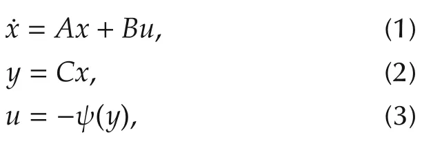

which is a square strictly proper transfer function.The nonlinearity ψ(y)is required to satisfy a sector condition,i.e.,

for some real matrices Kminand Kmax,where K =Kmax-Kminis a positive definite symmetric matrix and the interior of Γ is connected and contains the origin.If Γ=Rp,then ψ(y)satisfies the sector condition globally,and it is said that ψ(y)belongs to a sector[Kmin,Kmax][9].
The system in equations(1)-(3),where ψ(y)satisfies a sector condition in equation(5),is absolutely stable if the origin is globally uniformly asymptotically stable for any nonlinearity in the given sector.It is absolutely stable with a finite domain if the origin is uniformly asymptotically stable[9].The asymptotic stability condition of the origin is established in Lyapunov’s stability theorem[9].
3 Actuator domain intervals
Consider the SISO system to be controlled consisting of a rational function model of linear system P(s)in cascade with the actuator modeled by operator A(u).Define the disjoint sets
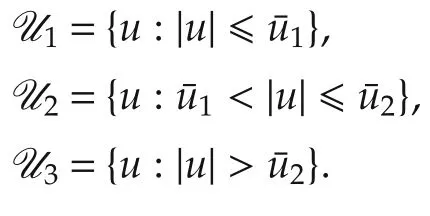
For actuators considered in this work,A(u)satisfies superposition in u ∈U2and does not hold for inputs in U1∪U3.Inputs in U2are considered in the nominal operating domain,those in U3overdrive the actuator,and those in U1are sufficiently small so that the response is substantially influenced by actuator imperfections(e.g.,stiction).
4 Nonlinear dynamic compensation schemes
Nyquist-stable control is sensitive to changes in loop gain,as adequate margins of stability are usually established over narrow frequency intervals.Shifts in loop gain caused by actuator nonlinearities will produce oscillations,and as such its application to systems with nonlinear actuators is particularly dangerous.The actuator typically has reduced gain in response to inputs in intervals U1and U3compared to those in U2for which the linear compensator for the Nyquist-stable controller is designed,and stability is threatened as discussed previously.The nonlinear feedback connections between C(s)and A(u)shown in Fig.2 make up the NDC,designed to reshape the loop transmission in U1∪U3to retain stability and performance.
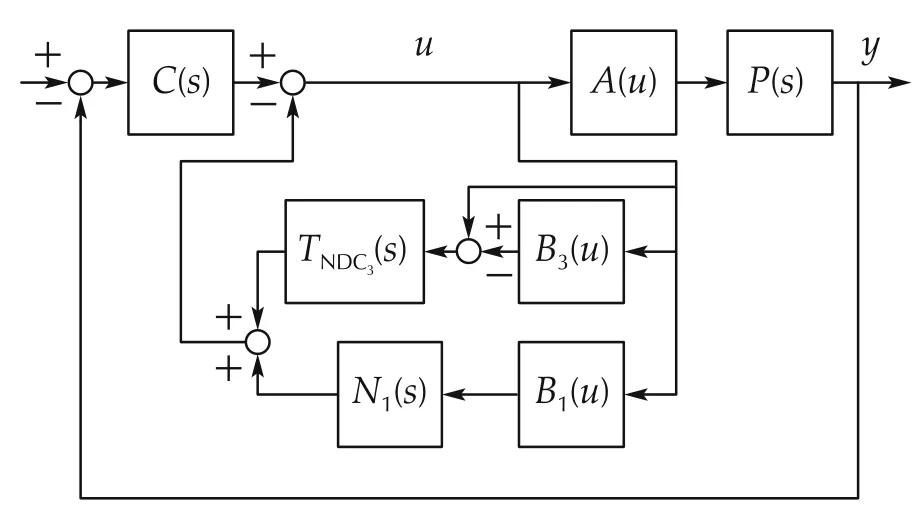
Fig.2 Block diagram of the NDC.
The designer often knows A(u)exactly for u ∈U3as this is usually a saturation,but not for u ∈U1.Nonlinear dynamic compensation for the known actuator saturation limits(consisting of systems TNDC3and B3)must be implemented to avoid oscillations when overdriven.Details of such a design is found in[38].A design for the N1NDC path is proposed with the assumption that the uncertain U1nonlinearities reduce actuator responsiveness,and the output is on or below the unit gain line.As such,it can be assumed that A(u)is confined to the sector[0 1]for u ∈U1.It is noted that if the designer has a priori knowledge that loop nonlinearities are not confined to this sector,a larger sector must be selected that subsumes all expected functions.
As the interval U1is not exactly known,engineering judgment is used to select parameter1eas an estimate of this width to define function B1(u),

The parameter should be selected so1e>1,but not so large that the NDC is heavily active in u ∈U2.
It is assumed that the actuator limit,act,is a known parameter used to define B3(u).

4.1 Gain-decreasing nonlinear dynamic compensation(GDNDC)
The complete NDC system consists of two nonlinear designs that are active in small and large signal conditions,the U1and U3NDCs,respectively.The NDC of Fig.2 may be designed to reduce the loop transmission so that Teq(s),the equivalent linear system in feedback connection to the nonlinear system A(u),satisfies the conditions of absolute stability[9]with the condition A(u)confined to a given sector(in this work,the sector is[0 1]);this is referred to as a gain-decreasing nonlinear dynamic compensator[36].
4.1.1U1NDC
Consider the loop transmission function,

where P(s)is a transfer function model of the plant dynamics in the linear condition,and CAS(s)is the compensator such that TAS(s)=Teq(s)satisfies the conditions of absolute stability for the given sector.For|u|≤1e,the system of Fig.2 is equivalently a feedback connection of the sector nonlinearity with a linear system having the following transfer function.

C(s)is the compensator designed for linear operation(i.e.,T(s)=C(s)P(s),a high performance loop transmission that lacks absolute stability over sufficiently wide sectors).If Teq(s)=TAS(s),the resulting feedback system is absolutely stable on the finite domain|u|≤1e.This is the GDNDC.
4.1.2U3NDC
It is assumed that B3is an accurate model of the actuator saturation.As such,the outputs of systems A and B3are equal,and the transfer function of the equivalent linear system in feedback connection to the sector nonlinearity is as follows:

If A(u) = B3(u)and TNDC3(s)is selected such that Teq(s)=TAS(s),then the U3NDC would alone provide stability.However,the saturation function does not model the effects of the U1nonlinearities and the U3NDC does not compensate for them,thus necessitating the inclusion of the U1NDC described previously.Experimental data indicating the necessity of multiple-path NDC for imperfect actuators is provided in the sequel.
4.2 Gain-increasing nonlinear dynamic compensation(GINDC)
In contrast to the gain-reduction approach,the focus of this work is the implementation of nonlinear dynamic compensation to re-introduce loop gain lost to mechanism imperfections in the system.The GINDC seeks to reestablish the original Nyquist-stable loop shape when u ∈U1(referring to Fig.2,this is the loop transmission C(s)P(s)in U2).In this case,the B1(u)nonlinear function is identical to the gain-decreasing NDC,however the rational function N1(s)is found with a different goal in mind.In the gain-increasing design,N1(s)is found so that

where P1(s)is the transfer function model of the actuator/plant response under the influence of the U1nonlinearities.This approach reestablishes the Nyquist-stable loop shape(C(s)P(s))for the particular response modeled by P1(s),and the closed-loop system will have greater disturbance rejection than the gain-decreasing NDC.While C(s)P(s)satisfies the Nyquist Stability Criterion,the system with gain-increasing nonlinear compensation that reestablishes this loop shape clearly does not satisfy the sufficient condition of absolute stability for the[0 1]sector in the finite domain|u|≤1e.This illustrates the contrast in the GDNDC and GINDC approaches to nonlinear dynamic compensation:the former satisfies conservative absolute stability conditions,the latter directly compensates for the effects of loop nonlinearities to retain high performance.
4.3 Parallel loop recovery(PLR)
For GINDC,N1(s)is designed using a frequency response measurement of the plant for a selected U1input(P1(s)models this)so that the original Nyquist-stable loop transmission is reestablished.However,plant frequency responses in U1may be quite sensitive to input amplitudes in this interval due to contact type nonlinearities,e.g.,stiction.Hence,the GINDC design may perform well for control signals similar to the test signal,and poorly for other signals in U1.Considering the reestablished loop shape is Nyquist-stable,the sensitivity to errors in the recovered loop transmission include the plant model modulus being either too high or too low(in both cases,excessive positive feedback may result).
More accurate reshaping of the loop in U1is established with the PLR system shown in Fig.3(without the quiescent compensator to be described in the sequel).As opposed to one model of the plant response in U1,multiple models of the plant are identified at different input amplitudes,and associated NDC gain-increasing systems are designed.The linear systems N1i(s)for PLR satisfy the following equality condition:

for mU1plant responses of diminishing modulus at low frequency(i.e.,for ω1less than the control bandwidth,|Pi(jω1)|>|Pi+1(jω1)|,i=1,2,...,m-1).
The associated nonlinear functions B1i(u)are described by the following equation:

Threshold values are selected using observations of system responses and engineering judgment,and satisfy u11>u12>...>u1m>0.
4.4 Parallel loop recovery with quiescent compensation(PLRQC)
PLR restores large loop transmission in U1through blended compensation designed using black box models of the system frequency response to selected low amplitude inputs.Imperfect actuators,for example,those exhibiting stick/slip characteristics,respond in very low U1dramatically differently than they do to larger amplitude inputs.For such systems,the model quality is poor,and the aggressive design approach to reestablish large feedback in this condition is contraindicated,as the resulting loop shape may not be what the designer intended.An additional consideration is that large feedback in this condition is not necessary as the disturbance power is likely very low.
For such systems,PLR is modified to include quiescent compensation,whereby a subset of the U1NDC linear systems associated with compensation in the lower signal amplitudes are designed to reduce loop transmission as opposed to increase it.A block diagram of the PLRQC is shown in Fig.3.NDC systems N11(s)through N1(m-1)(s)are loop recovery systems described previously to reestablish the Nyquist-stable loop shape for high U1inputs.System N1m(s)reduces loop transmission for low U1inputs.PLRQC trades feedback for increased robustness in the quiescent(or near-quiescent)operating condition,and as such,slightly reduced disturbance rejection is expected over the functional bandwidth in the nominal operating condition.
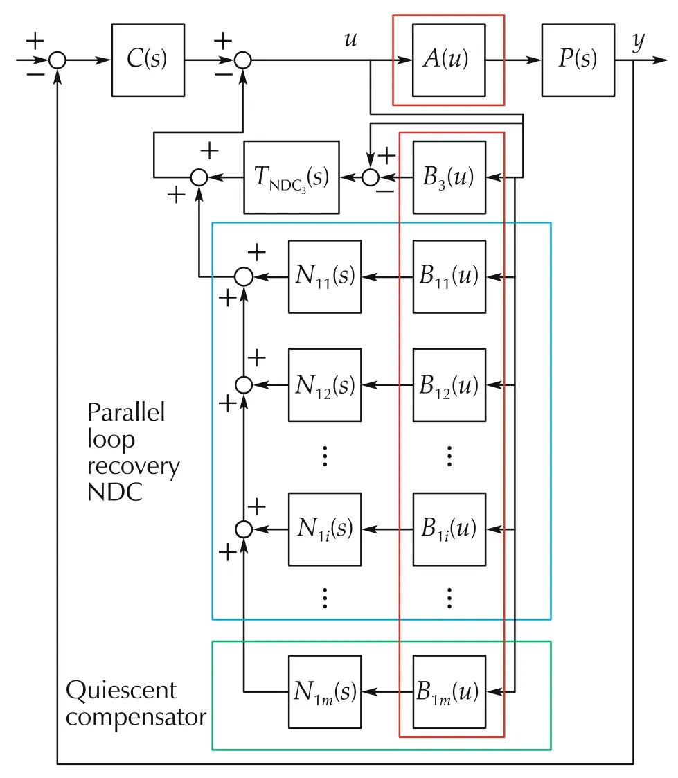
Fig.3 Parallel loop recovery nonlinear dynamic compensator with quiescent compensation.
5 Stability analysis
Considering the system possesses uncertain nonlinear subsystems,the absolute stability of the feedback system is assessed over sectors to which these nonlinearities are assumed to be limited[9].For the case of U3NDC only(Section 4.1.2)to provide stability in the presence of actuator saturation(the only nonlinearity in the system),B3(u)=A(u)=sat(u),and absolute stability of the single-input and single-output(SISO)system can be determined using the Nyquist or Popov plots of Teq(s)in equation(10).The introduction of an uncertain nonlinearity(one for which an equation is not available,however memorylessness and confinement to a particular sector is assumed)in the forward path with attendant nonlinear NDC paths(i.e.,U1gain-decreasing and gain-increasing systems)complicates absolute stability assessment,and despite the system being SISO,an alternative analysis is indicated.
For the U1NDC systems,the loop is treated as a multiple-input and multiple-output(MIMO)system shown in Fig.3.The systems of Figs.2 and 3 are reexpressed as(m+2)×(m+2)(m the number of U1NDC paths)MIMO feedback systems.Lower and upper sector bounds for each decoupled channel reside on the diagonals of diagonal matrices Kminand Kmax,respectively.
The R(m+2)×(m+2)(s)transfer matrix,Teq(s),for the equivalent linear system in feedback connection to the nonlinear system has identical rows consisting of
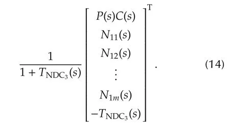
The nonlinear feedback system is absolutely stable if the origin is asymptotically stable for any nonlinearity in the sector[KminKmax][9].An application of Lyapunov’s basic theorem and the Kalman-Yakubovich-Popov Lemma,the Multivariable Circle Criterion establishes a sufficient condition for absolute stability[9].
1)Sector condition(5)is satisfied;
2)M(s)=Teq(s)[I+KminTeq(s)]-1is stable;and
3)ZT(s)=[I+KmaxTeq(s)][I+KminTeq(s)]-1is strictly positive real.
The stability of system M(s)(item 2)is determined graphically using the Generalized Nyquist Theorem[39](the characteristic loci of loop transmission matrix Kmin×Teq(s)must encircle the critical point P0times anticlockwise(P0the number of unstable Smith-McMillan poles of Teq(s))).Proper,square rational transfer matrix ZT(s)is strictly positive real(item 3)if
1)All poles of elements of ZT(s)have negative real parts;
She sprang from the seat and exclaimed, Stop prying3 the nails! We will continue renting the house and will only move away after we buy our own! He looked at her with great surprise, and then turned round, tearing over his face.

6 Experimental case study
The control approach is tested on a parallel mechanism with two degrees of freedom(two-DOF parallel mechanism)shown in Fig.4,developed as part of an ongoing investigation of the implementation of parallel robots in vibration suppression applications[40,41],followed by[38,42]and[43,44].The control goal is to provide as much disturbance rejection as is feasible subject to practical limitations.While the mechanism has two-DOF,the experiment will focus on only one of these,namely the regulation of the voice coil(prismatic actuator)at its home configuration.The unique architecture decouples the task DOFs,and as such,similar control can be applied to the second actuator.
As large disturbance rejection is required,a Nyquiststable controller with nonlinear dynamic compensation is designed.System identification indicates that while the mechanism responses are principally linear,imperfection nonlinearities cause an undesired reshaping of the plant frequency response at low input amplitudes.Two NDC design approaches are investigated in details:
1)NDC reshapes the loop for less aggressive feedback in U1∪U3(gain-decreasing NDC).
2)PLRQC.
The PLRQC compensator has higher performance than GDNDC as it is a partially gain-increasing scheme.The reduction in localized positive feedback of the PLRQC system when compared to a strictly gain increasing system(GINDC or PLR)is evident in data presented in the sequel.
6.1 Section terminology
Exogenous disturbances are applied to the feedback system are zero mean Gaussian signals input to the actuator driver in levels defined by rms:Levels 0 and 1 are very low(variance of Level 0 signal less than that of Level 1),generating control inputs in U1;Level 2 is low,generating control inputs in both U1and U2,Level 3 is nominal,generating inputs principally in U2;and Level 4 is high,frequently generating amplitudes exceeding the control signal limit set in software at±0.2 V.
6.2 Plant architecture
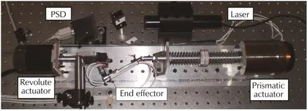
Fig.4 US-R parallel robot.
6.3 System identification
It is desired to gain-stabilize all high-frequency modes in the plant.This constraint along with the third-order roll-off of the plant response starting in the 50-100 Hz interval forces a control bandwidth of approximately 40 Hz.A 10 Hz functional bandwidth is desired,thus allowing only two octaves between the loop transmission break and crossover,necessitating a Nyquist-stable loop shape to achieve high performance.
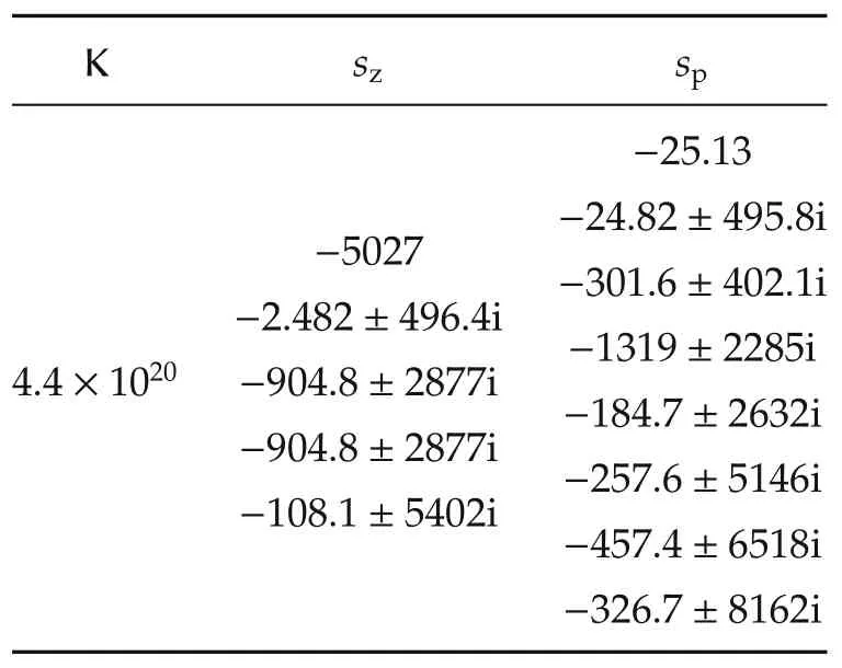
Table 1 PZK model of the plant P(s).
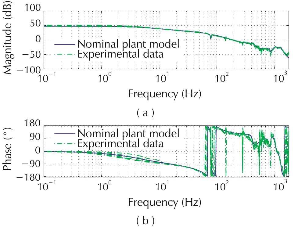
Fig.5 US-R plant frequency response.
6.4 Nyquist-stable compensator design
A high performance Nyquist-stable controller C(s)is designed with the goal of providing large disturbance rejection at frequencies below the 10 Hz functional bandwidth.C(s)is designed using the loop shaping method whereby compensator poles and zeros are chosen to warp T(s)=C(s)P(s)to the desired shape:
▪A zero at 4 Hz flattens the response below the 10 Hz functional bandwidth.
▪Conjugate pole pairs at 7 Hz and 10 Hz provide the break at the functional bandwidth.
▪The pole pair at 10 Hz and a zero pair at 15 Hz provide the sharp transitions seen in the slope of the loop transmission in this frequency interval.
▪A pair of zeros at 60 Hz and a pair of poles at 200 Hz flatten the response.
▪A two octave wide lead filter centered at 100 Hz further flattens the response and adds phase lead.
▪The loop shape is such that the positive feedback never exceeds 6 dB.
▪The gain,zeros,and poles of C(s)are presented in Table 2.
The resulting 7th order compensator provides approximately 38 dB of disturbance rejection below 10 Hz(63 rad/s),as seen in the Nichols plot of C(s)P(s)shown in Fig.6.The control bandwidth is approximately 40 Hz(251 rad/s).
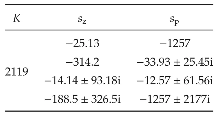
Table 2 PZK model of the compensator C(s).
The controller oscillates in saturation(U3)and in response to low disturbance power(U1),necessitating a multiple-loop NDC to provide absolute stability.
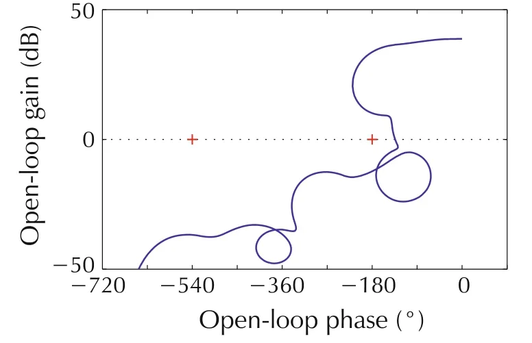
Fig.6 Nyquist-stable controller loop transmission.
6.5 System identification 2:plant response to low input power
The plant frequency response moduli for six input rms values from 0.01-0.60Vrmsare shown in Fig.7.Within a few dB of each other,the inputs associated with the green(0.4Vrms)and dark blue functions(0.6Vrms)are considered principally in U2,or what is expected in nominal mechanism operation.Larger input amplitudes that do not saturate the actuator result in frequency responses that roughly overlap the blue function,suggesting the system is very nearly linear and is treated as such for these inputs.
It is noted that responses to input amplitudes from 0.05-0.20Vrmshave reduced moduli at frequencies below 200 Hz(several octaves higher than the control bandwidth).The slope is roughly first order for all responses,and the only significant difference below 100 Hz is the zero-pole combination at 80 Hz associated with the helical spring.As such,the imperfections of the plant primarily affect a gain shift in the plant response.The response to the 0.01Vrmsinput,however,significantly differs in that it is zero slope.This response suggests the dominant effects of joint imperfections in the nearly quiet condition.
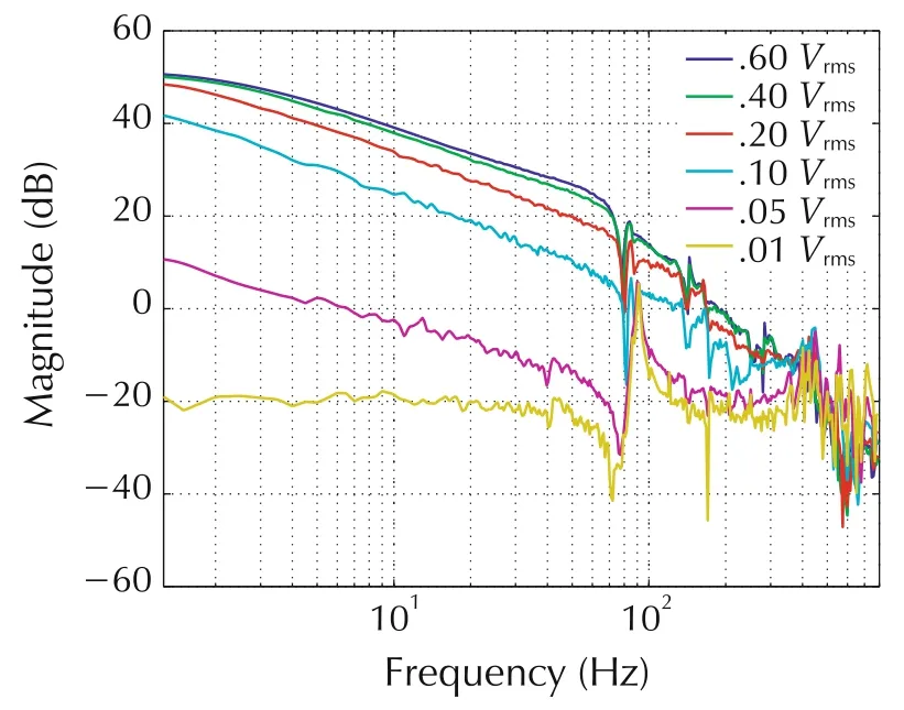
Fig.7 Plant response to zero-mean white noise stimulus of different variances.
The plant satisfies(in an approximate sense)superposition for what can be termed“mid-range”input amplitudes,responds nonlinearly to small signals,and saturates when driven by large signals.The first step in the control development is the design of a Nyquist-stable controller for the mid-range response with nonlinear dynamic compensation for actuator saturation.After verifying the required attenuation of the effect of exogenous forces on the robot pose with inputs principally in U2and stability in saturation(u ∈U3),the effects of operation in U1are evaluated and additional nonlinear compensation is designed.
6.6 U1 gain decreasing nonlinear dynamic compensator design
A single path,gain decreasing NDC is designed.Referring to Fig.3,the NDC consists of linear systems TNDC3(s)and N11(s)(N1(s)in Fig.2 and nonlinear systems B3(u)and B11(u).The gain,zeros,and poles of TNDC3(s)are given in Table 3.
B3(u)is the saturation nonlinearity with a limit of 0.2(this is the limit of the voice coil)[38].The gain,zeros,and poles of N11(s)for the gain-decreasing U1NDC are presented in Table 4.B11(u)is the saturation function with limit 0.0055.The gain,zeros,and poles of compensator CAS(s)are summarized in Table 5.
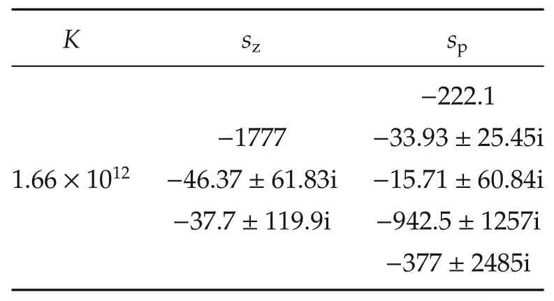
Table 3 PZK model of the TNDC3(s).
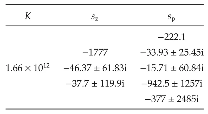
Table 4 PZK model of the N11(s).
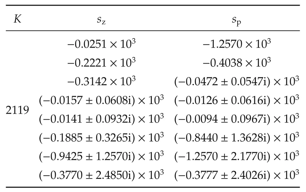
Table 5 PZK model of the CAS(s).
Sectors are selected for absolute stability analysis.As there are three nonlinearities in this system(actuator nonlinearity in the forward path A(u),and two NDC nonlinear functions B11(u)and B3(u)),the matrices defining the upper and lower limit(Kmaxand Kmin,respectively)for a given sector are R3×3.These matrices are chosen to be diagonal with individual channel limits ordered thusly:the(1,1)entries define the sector to trap A(u),the(2,2)entries correspond to B11(u),and the(3,3)entries correspond to B3(u).It is noted that the NDC nonlinearities are known functions,while A(u)is not.The analysis seeks to determine finite domains over which the 3×3 system satisfies the Circle Criterion.
Absolute stability analysis is presented for this system.Satisfaction of the conditions of the Multivariable Circle Criterion listed in Section 5 for this system are verified for two sectors[KminiKmaxi],i=1,2.
6.6.1 Sector 1
Sector 1 is Kmin1=diag{0, 0.9, 0.9999},Kmax1=diag{0.33,1,1}.This sector is selected to determine stability for small signal nonlinear responses of A(u)(for this case,the system is stable for any nonlinearity in the sector[0 0.33]).Fig.8 shows the characteristic loci for Kmin1Teq(s);there are no encirclements of the critical point(-1+j0)and as the open loop system is stable,M(s)is stable by the Generalized Nyquist Theorem(condition(2)in Section 5.Fig.9 shows the minimum eigenvalues of Z(jω)+ZT(-jω)as a function of frequency,showing that conditions(2)and(3)for strict positive reality in Section 5 are satisfied(all poles of Z(s)have negative real parts,condition(1)),thus condition(3)of the Circle Criterion is satisfied and the system is absolutely stable over this sector.Recall the B11(u)is the saturation with limit 0.0055,so the lower sector limit of 0.9 intersects this at u=±0.0061,and thus this is the domain for which the system is absolutely stable for this sector(approximately 3 percent of the actuator range).
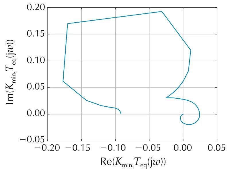
Fig.8 Characteristic loci Kmin1Teq(s)for the U3 and gain-decreasing U1 NDC.Two of the three loci are very small magnitude.
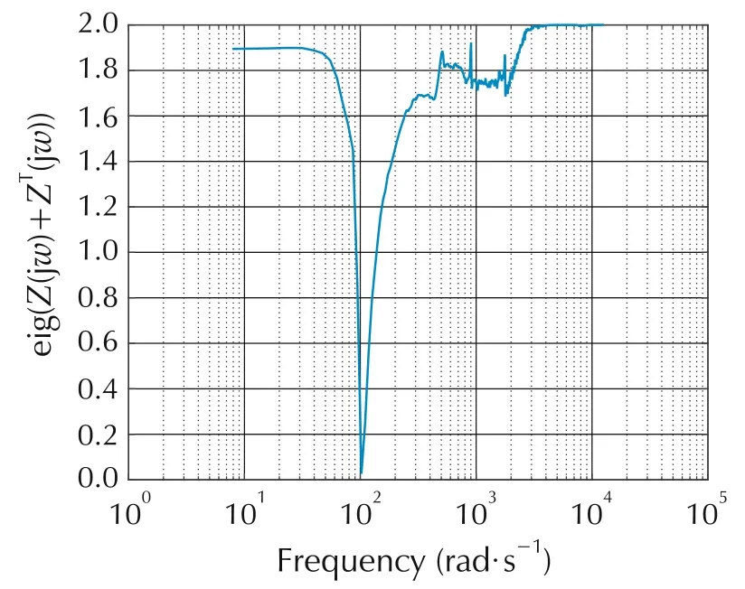
Fig.9 Minimum eigenvalue of Z(s)(for Kmin1,Kmax1)versus frequency for the U3 and gain-decreasing U1 NDC.
6.6.2 Sector 2
Sector 2 is Kmin2=diag{0.5,0.0275,0.9999},Kmax2=I.The(2,2)and(3,3)elements are selected to determine the sector for A(u)(i.e.,the(1,1)elements)for which the system is absolutely stable over the range of the actuator±0.2 V(note that saturation B11is subsumed by sector[0.0275 1]over domain[-0.2 0.2]and B3is unit gain over the range of the actuator).Fig.10 shows the characteristic loci for Kmin2Teq(s);there are no encirclements of the critical point(-1+j0)and as the open loop system is stable,M(s)is stable by the Generalized Nyquist Theorem(condition(2)in Section 5).Fig.11 shows the minimum eigenvalues of Z(jω)+ZT(-jω)as a function of frequency,showing that conditions(2)and(3)for strict positive reality in Section 5 are satisfied(all poles of Z(s)have negative real parts,condition(1)),thus condition(3)of the Circle Criterion is satisfied and the system is absolutely stable over this sector(the system is stable for any nonlinearity A(u)in sector[0.5 1]over the range of the actuator).
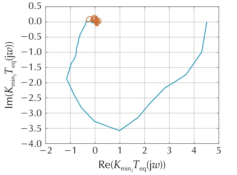
Fig.10 Characteristic loci Kmin2Teq(s)for the U3 and gain-decreasing U1 NDC.
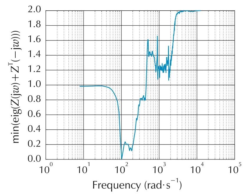
Fig.11 Minimum eigenvalue of Z(s)(for Kmin2,Kmax2)versus frequency for the U3 and gain-decreasing U1 NDC.
6.7 PLRQC
PLRQC is applied to the parallel mechanism.Four U1plant responses(Pj(s),j=1,2,3,4)of diminishing modulus at low frequency(i.e.,over the control bandwidth,the modulus of P1(s)is greater than P2(s),etc.)are modeled.Note that experimentally acquired frequency response data can be used as a surrogate for rational functions fitted to the data.Threshold values for the nonlinear functions described in equation(13)are selected using engineering judgment,and linear systems are found using equation(12).The pole-zero-gain representations of the PLR linear systems are summarized in Tables 6-9.N14q(s)works in concert with the other three systems of the PLR to reduce the loop transmission in very low U1.B1i(u)are saturations with limits 0.014,0.012,0.005,0.003.B3(u)is identical to the GDNDC(saturation with limit 0.2).

Table 6 PZK model of the N11(s).

Table 7 PZK model of the N12(s).

Table 8 PZK model of the N13(s).
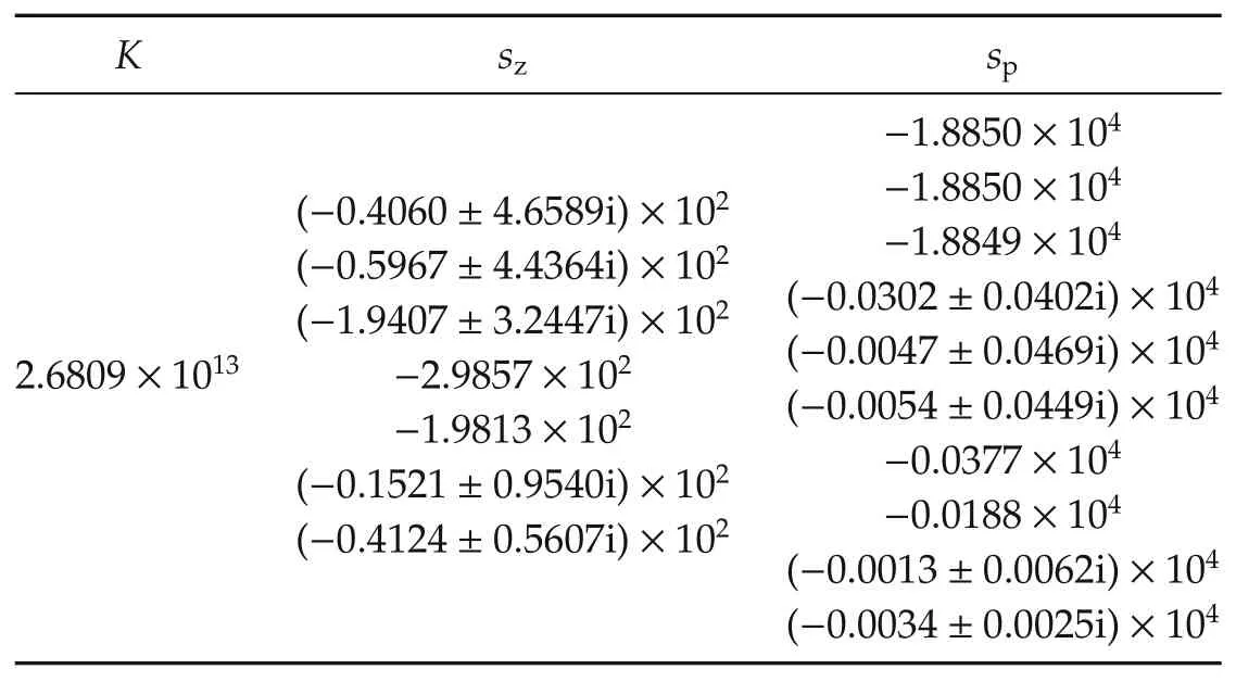
Table 9 PZK model of the N14q(s).
6.7.1 Sector 3
Sector matrices are 6×6 diagonal matrices.The(1,1)elements bound a sector for nonlinearity A(u),the(2,2)-(5,5)elements bound sectors for the four B1iNDC nonlinearities,and the(6,6)elements bound the B3nonlinearity.Sector 3 is Kmin3=diag{0,0.999,0.95,0.9,0.84,0.999}, Kmax3= diag{0.33,1,1,1,1,1}.This sector is selected to determine stability for small signal nonlinear responses of A(u)(for this case,sector[0 0.33]).Fig.12 shows the characteristic loci for Kmin3Teq(s);there are no encirclements of the critical point(-1+j0)and as the open loop system is stable,M(s)is stable by the Generalized Nyquist Theorem(condition(2)in Section 5.
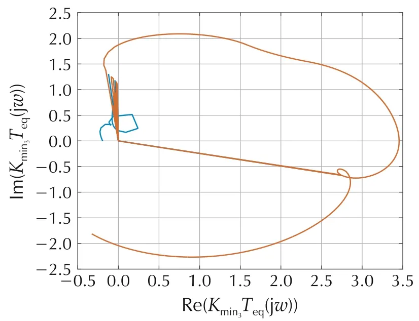
Fig.12 Characteristic loci Kmin3Teq(s)for the U3 and PLRQC.
Fig.13 shows the minimum eigenvalues of Z(jω)+ZT(-jω)as a function of frequency,showing that conditions(2)and(3)for strict positive reality in Section 5 are satisfied(all poles of Z(s)have negative real parts,condition(1)),thus condition(3)of the Circle Criterion is satisfied and the system is absolutely stable over this sector.
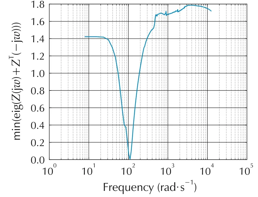
Fig.13 Minimum eigenvalue of Z(s)(for Kmin3,Kmax3)versus frequency for the U3 and PLRQC.
Recall the B14(u)is the saturation with limit 0.003,so the lower sector limit of 0.84 intersects this at u=±0.00357,and thus this is the domain for which the system is absolutely stable for this sector(approximately 2 percent of the actuator range).
6.8 Effect of quiescent compensation on response
Figs.14 and 15 show sensor signal spectra when the system is driven by Levels 1 and 2 disturbances.Each plot shows spectra for three closed-loop responses:a gain-increasing NDC(m=1 in equation(12)),PLR(m=4 in equation(12)),and PLRQC(m=5 in equation(12)).Performance comparisons of gain-decreasing and gainincreasing NDC schemes are presented in[36].The effect of quiescent compensation is evident in Fig.14,where reduced regenerative response is seen in the neighborhood of crossover viz-a-viz GINDC or PLR with the trade-off of less feedback applied over the functional bandwidth.This effect is reduced as the disturbance power is increased as evident in Fig.15.
In Fig.14,the superior performance over the 10 Hz(63 rad/s)functional bandwidth of the gain-increasing NDC designs(GI and PLR)in U1is expected,as the NDC reestablishes the large Nyquist-stable loop gain in this condition.The sharp peaks of regenerative response in the GINDC data due to the positive feedback in the octave 50-100 Hz are a consequence of the inadequacy of the single-path gain-reestablishment approach in U1.The peaks in the PLR response are substantially lower than those of GINDC while delivering the same performance over the functional bandwidth.An application of quiescent compensation further reduces the effect of positive feedback around crossover frequency,but also reduces performance over the functional bandwidth.With an increase in the disturbance power,system performance using quiescent compensation is greater than using GINDC or PLR,as demonstrated in Fig.15.PLRQC response shows better reduction of the regenerative behavior and larger amount of feedback applied over the functional bandwidth than other NDC designs.
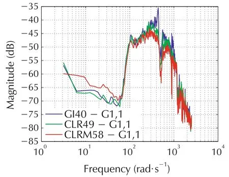
Fig.14 Level 1 disturbance responses.The blue function(GI40)is the response of the system with gain increasing NDC.The green(CLR49):PLR.The red(CLRM58):PLRQC.
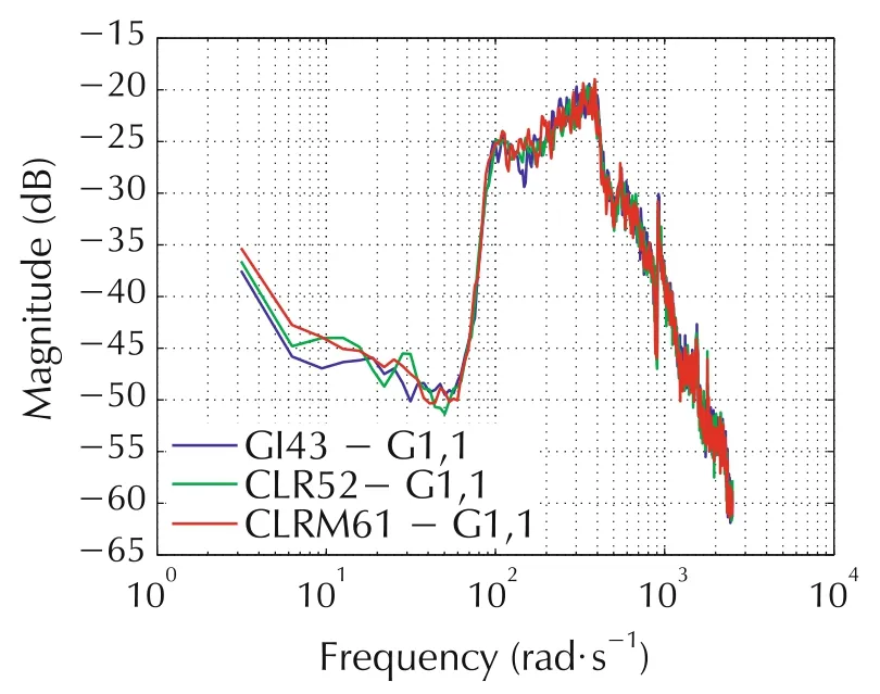
Fig.15 Level 2 disturbance responses.The blue function(GI43)is the response of the system with gain increasing NDC.The green(CLR52):PLR.The red(CLRM61):PLRQC.
7 Conclusions
A method to apply multiple nonlinear dynamic compensators combined with linear Nyquist-stable compensators for large-feedback/high-performance applications on systems with imperfect and limited actuators is presented.Large feedback linear controllers are very sensitive to variations in loop transmission and may oscillate when applied to systems with these actuators.The improved NDC approach maintains stability in actuator saturation and eliminates oscillation due to the influence of nonlinearities at low amplitude by effecting changes in the loop gain.The efficacy of the approach is shown with closed-loop data and multivariable absolute stability analysis on a voice-coil actuator used in a vibration suppression system.
杂志排行
Control Theory and Technology的其它文章
- Nonlinear observer-based control design and experimental validation for gasoline engines with EGR
- Invariant observer design of attitude and heading reference system
- On the mechanism and control for the ultra-low frequency oscillation in NY Power Grid with large-scale hydropower
- Guaranteed feasible control allocation using model predictive control
- Diagnosability of a class of discrete event systems based on observations
- Optimal finite-dimensional spectral densities for the identification of continuous-time MIMO systems
